 jaromir.sukuba
When playing this instrument, player has three ways of coloring its sound:
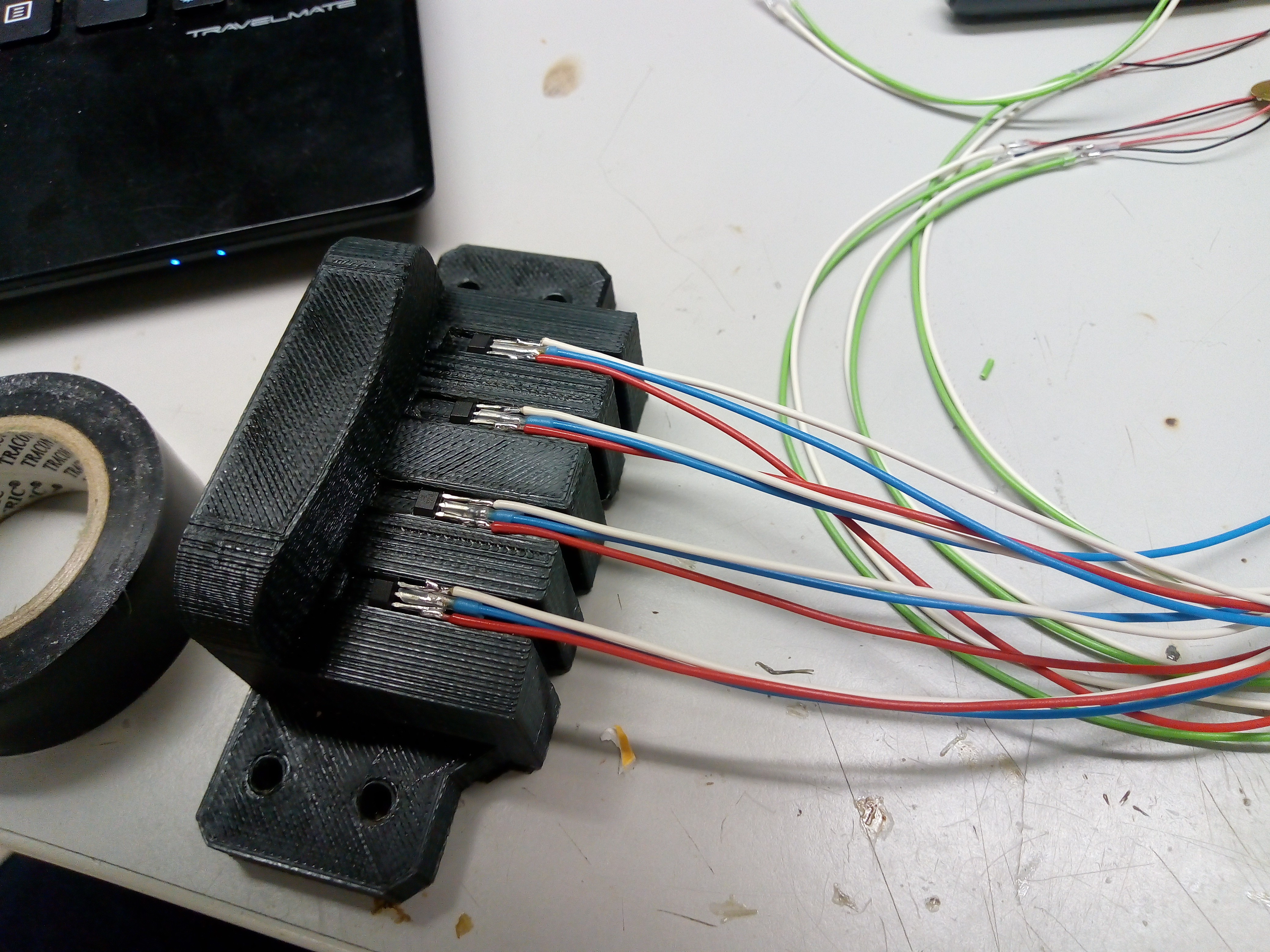
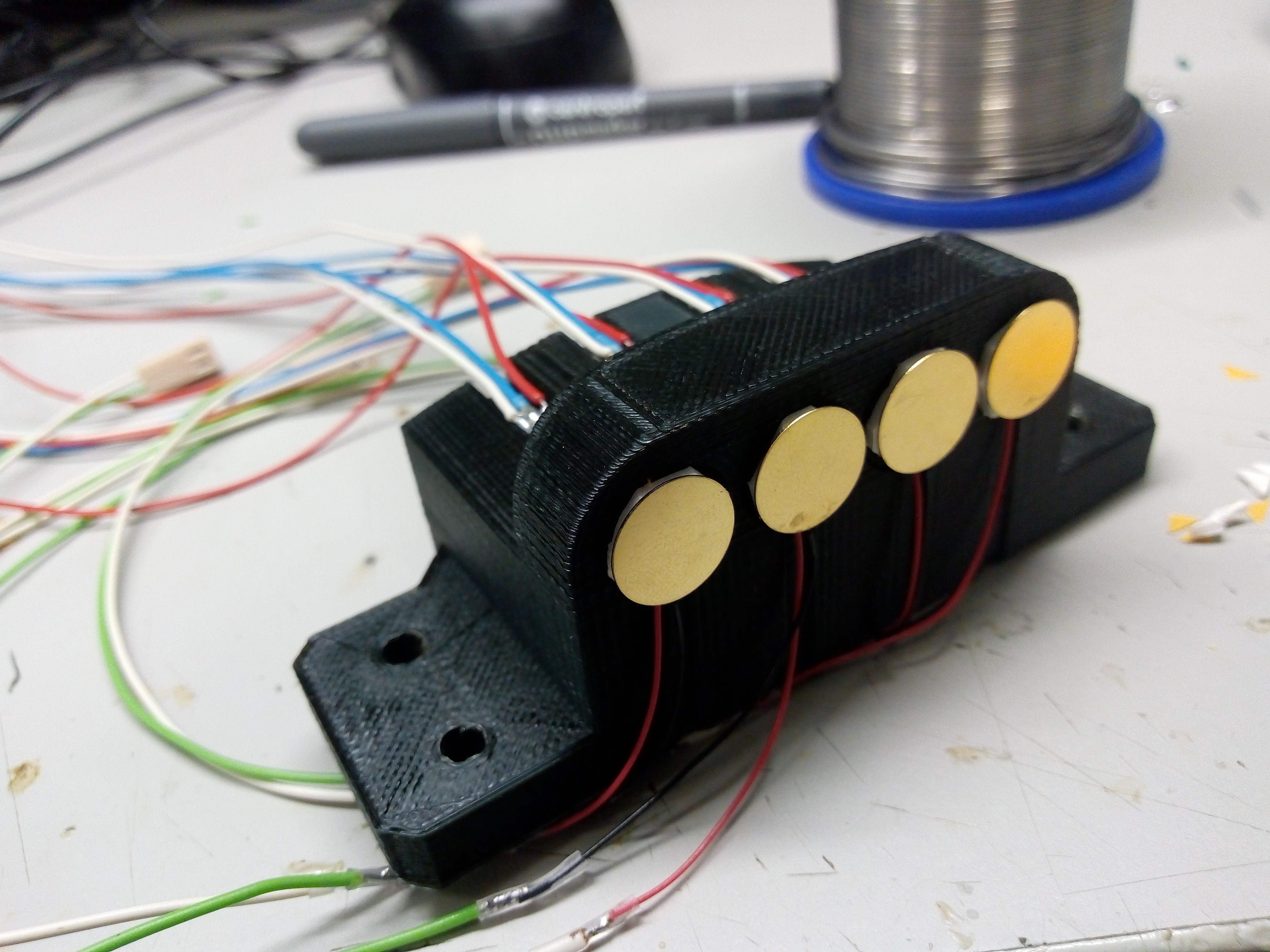
1, Magnetic sensors, one for each string. This one in engaged by drawing the magnetic strip bow across the sensor.
2, Tap sensors, again, one sensor for each string. Those are ordinary piezo speakers, placed under magnetic ones, are actuated by tapping fingers against the sensor, making pizzicato sound (equivalent to plucking the string of real cello with fingers).
Both the sensors are placed on 3D printed sensor head
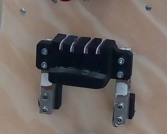
3, Force sensor - converting pressure of bow to electric signal. This is done by pair of 1kg load cells, carrying the sensor head.
First two sensors are mean to change gain of VCA (influencing sound volume, dynamics), force sensor is meant to adjust VCF, changing color of the tone, being generated as harmonics-rich sawtooth waveform in VCO.
Magnetic sensor is based on A1324 from Allegro. This is linear hall sensor, its output voltage being proportional to magnetic filed present at sensors place. When moving the magnetic strip bow above the sensor, it generates sine-like waveform, with frequency proportional to speed of bow movement. I used comparator to convert this voltage to square waveform
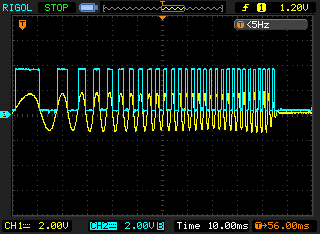
This is captured waveform of accelerating bow movement across the sensor (yellow line), along with comparator output. Now I have logic level signal, with frequency being proportional to desired variable (bow speed) and need to convert it to analog value to steer VCA. Here I can use old trick that multimeters use to meadure freqquency - monostable multivibrator 74LS123 to convert it to PWM signal with variable frequency, but constant pulse width. Then, it's just matter of low-pass RC filter to convert PWM signal to DC voltage. Complete schematics of single channel of magnetic sensor is here:
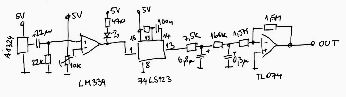 The low-pass filter is followed by inverter providing both impedance buffering as well as inverting needed for following stages.
Tap sensor is somehow simpler, but took me longer to develop.
At first I thought of using resistive pressure sensors, but I couldn't get them to work very reliably. Accelerometers and microphones were considered too, but at the end I opted for cheap disc piezo transducer, like this
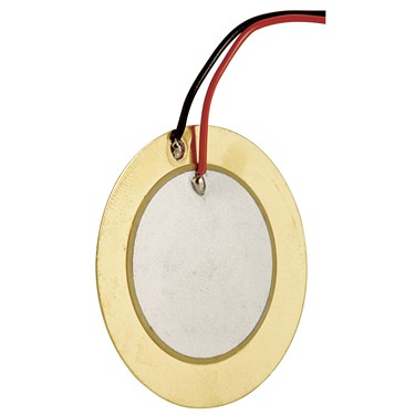 Usually those are used as sound transmitters, ie. being driven with voltage and creating mechanical output (sound). Reverse operation is also possible, where mechanical input is creating voltage signal on its terminals.
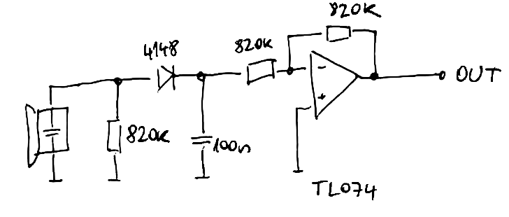 Main part of this circuit is resistor, diode and capacitor. After tapping on the sensor, voltage spike (blue waveform on picture below) charges the capacitor via diode, which is stopping its discharge when voltage on transducer is negative. Capacitor then slowly discharges into 820k - input impedance of the amplifier - see yellow waveform.
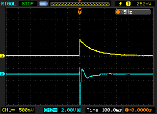
This circuit produces impulses with roughly exponential waveform, suitable for waveform shaping to emulate percussive sound of string being plucked with fingers.
Force sensor is just textbook use of load cells. I'm using differential amplifiers for the task
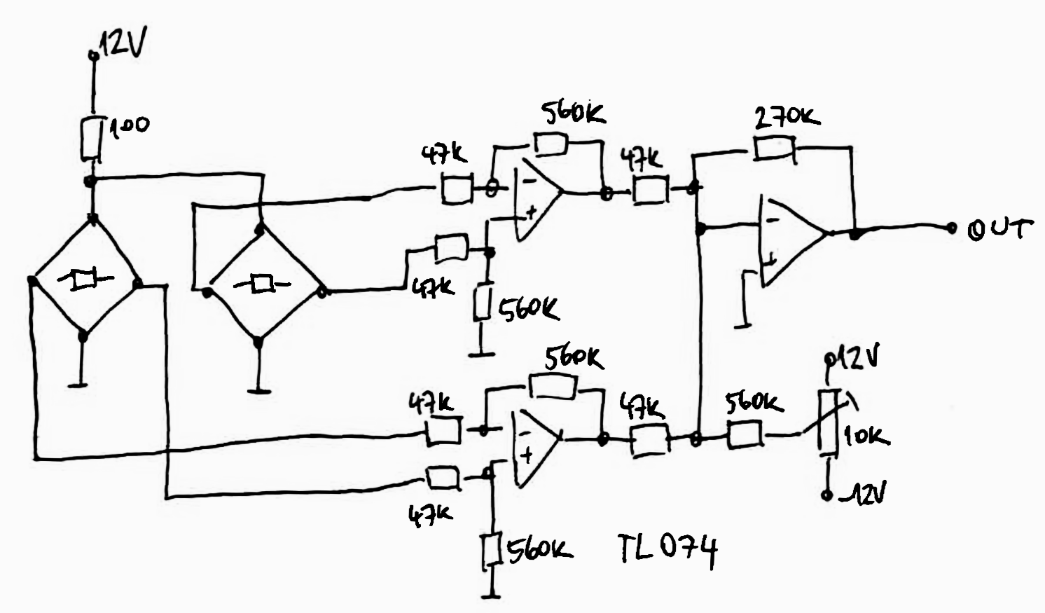
Outputs from amplifiers are brought into summing amp, along with trimmer output, allowing to bring offset and zero out the weight of sensor head.
Now I described a lot of separate blocks - VCO, VCA, VCF, sensors and amplifiers. In following projects logs I'll try to make sense of all of it, linking all the parts together.
Discussions
Become a Hackaday.io Member
Create an account to leave a comment. Already have an account? Log In.