0%
0%
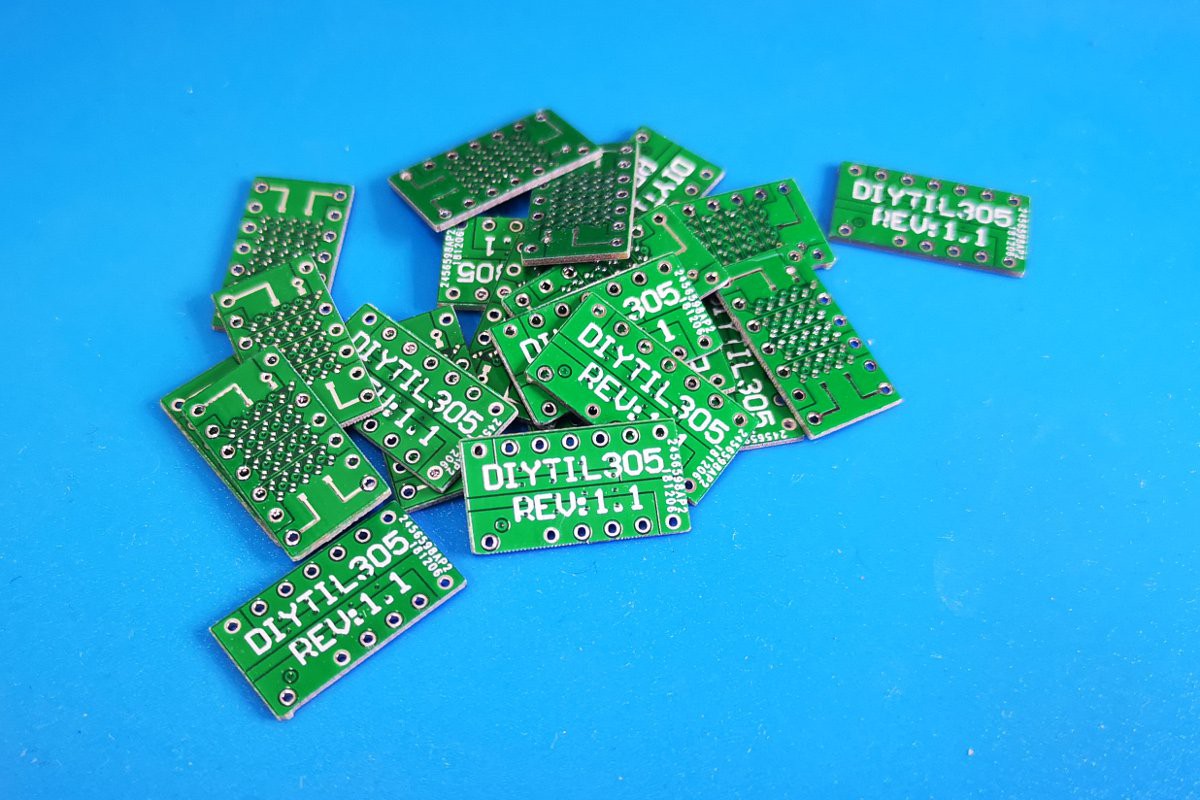
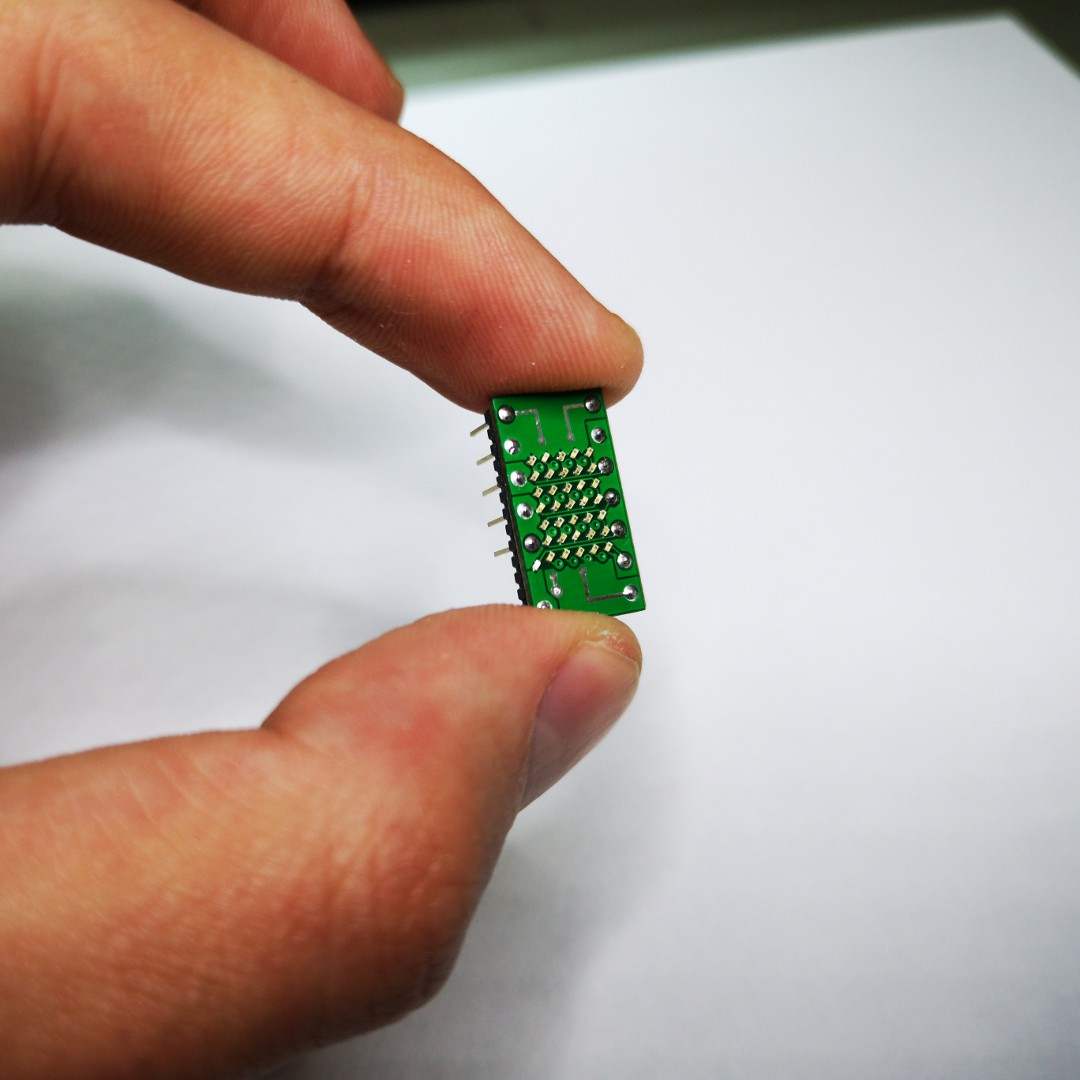
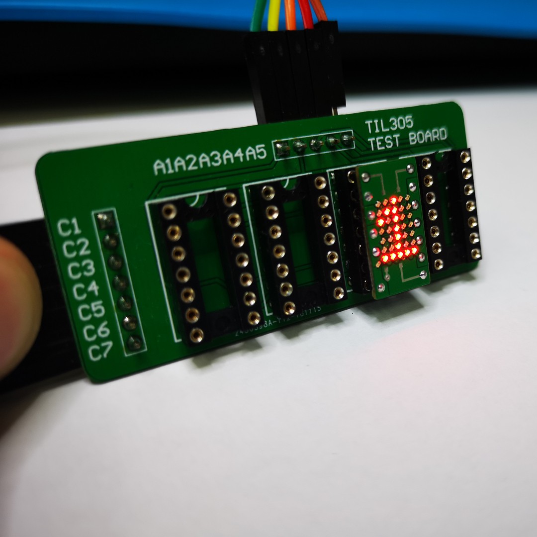
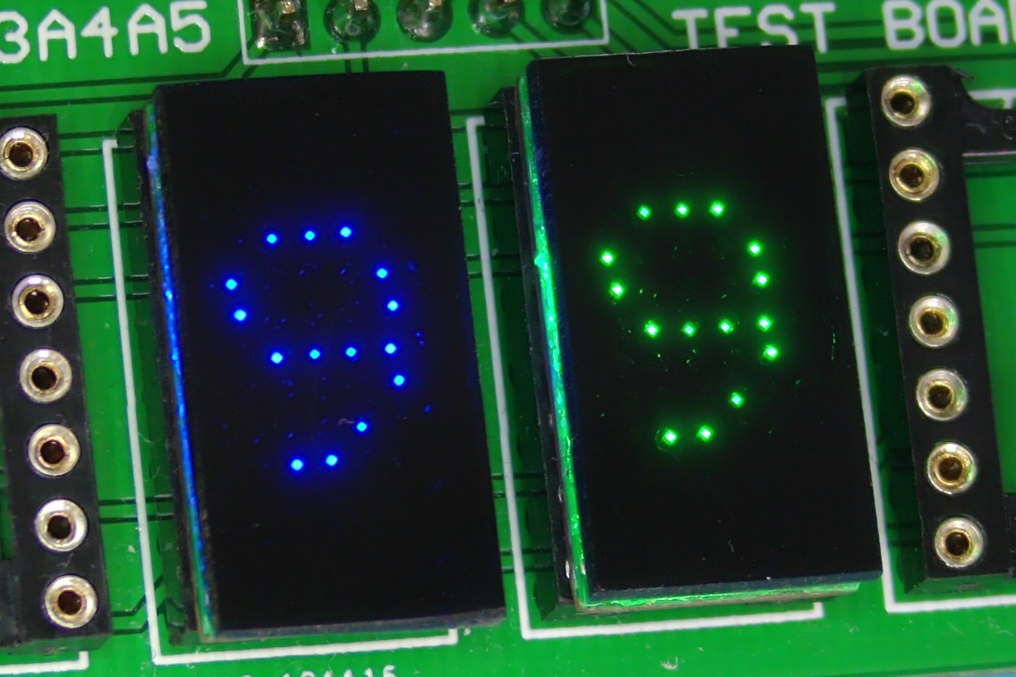
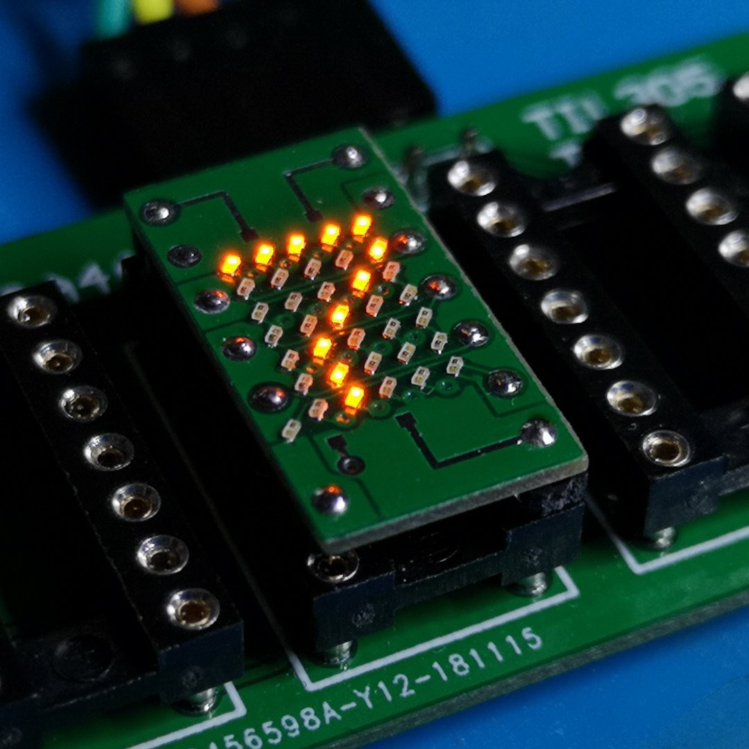
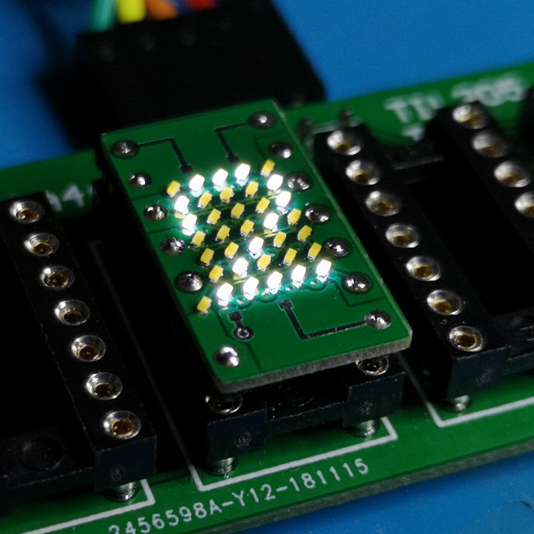
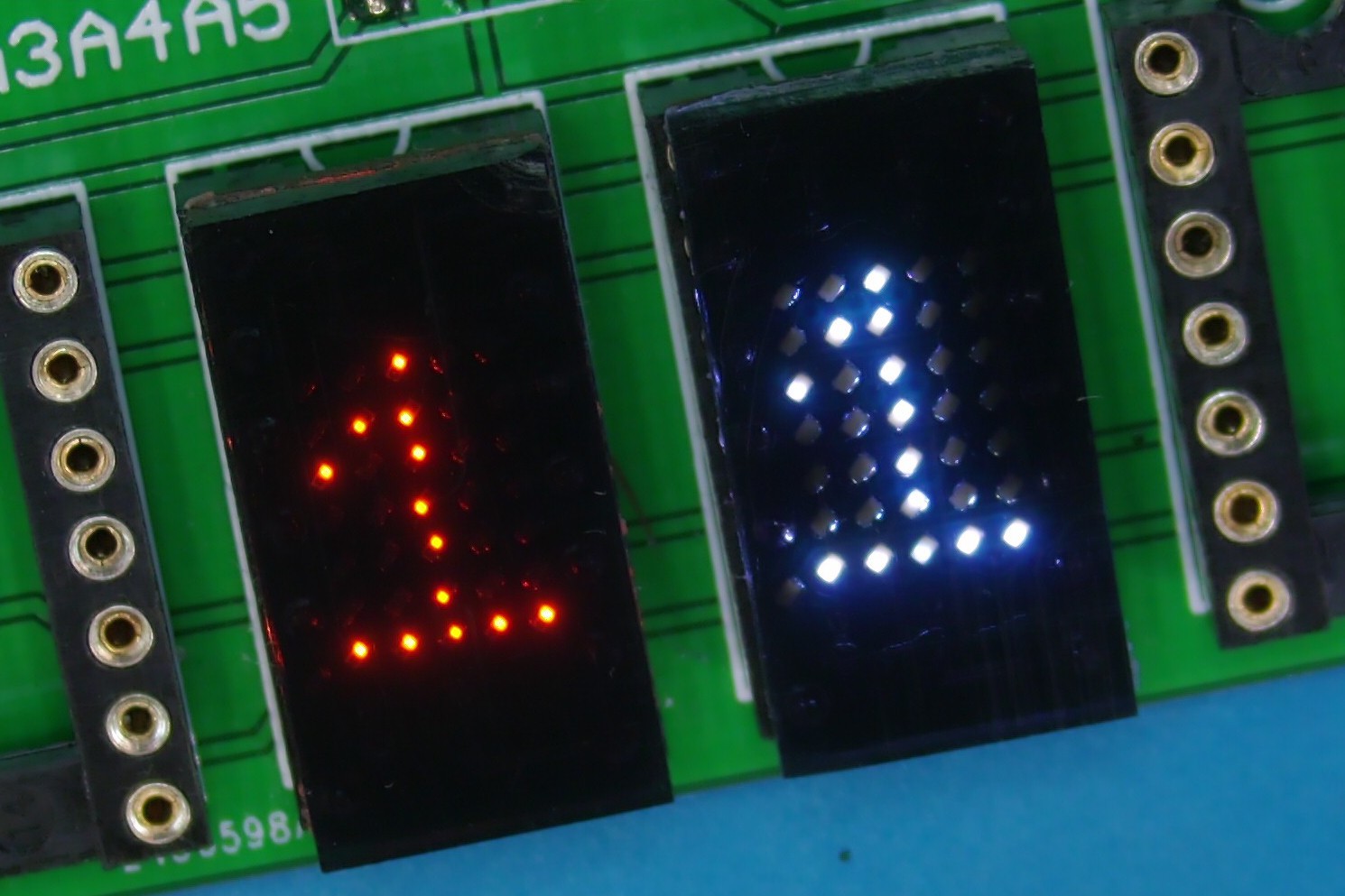
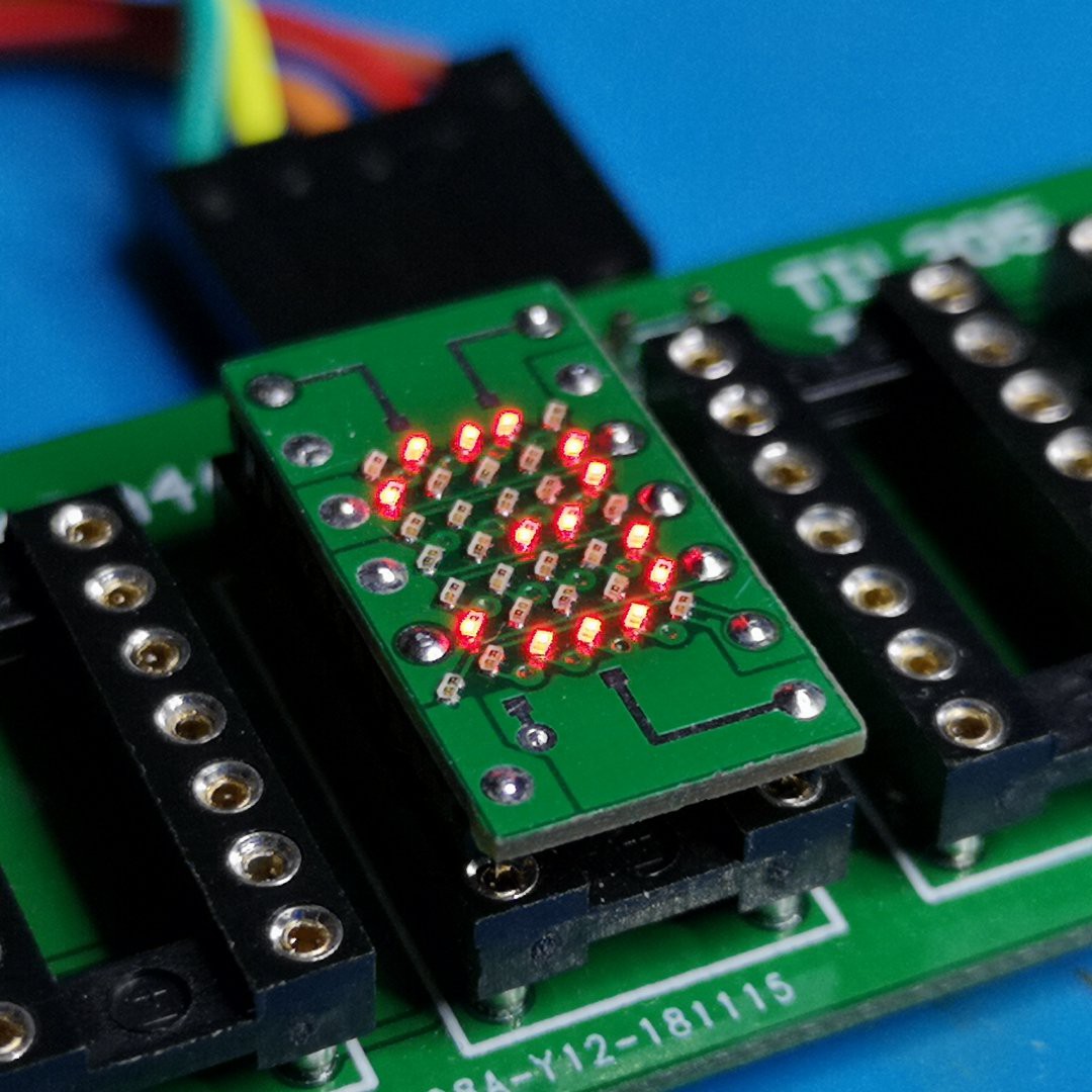
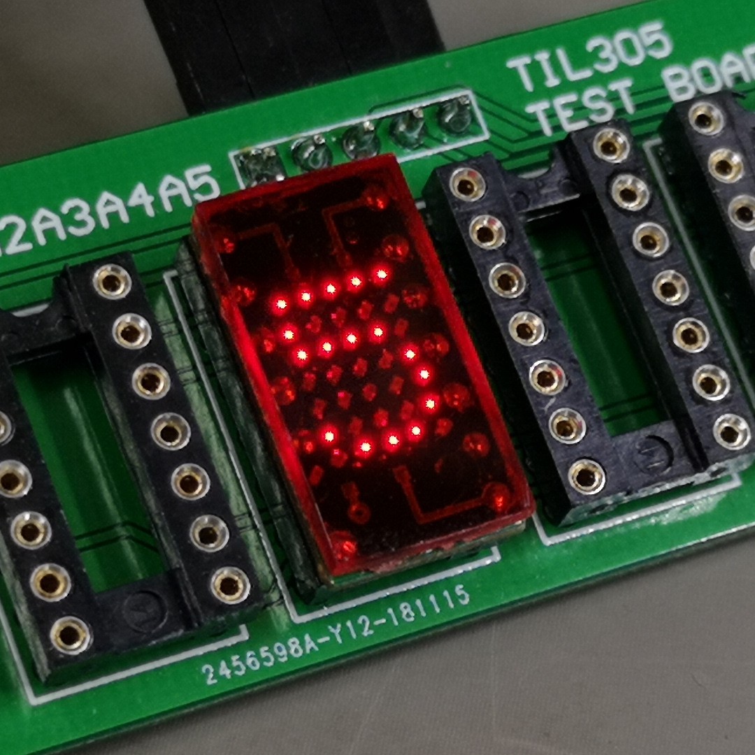
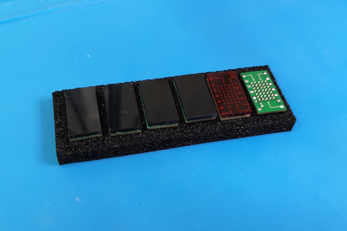
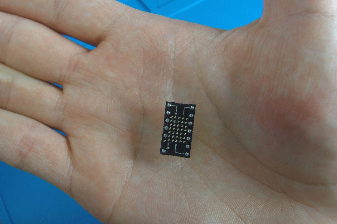
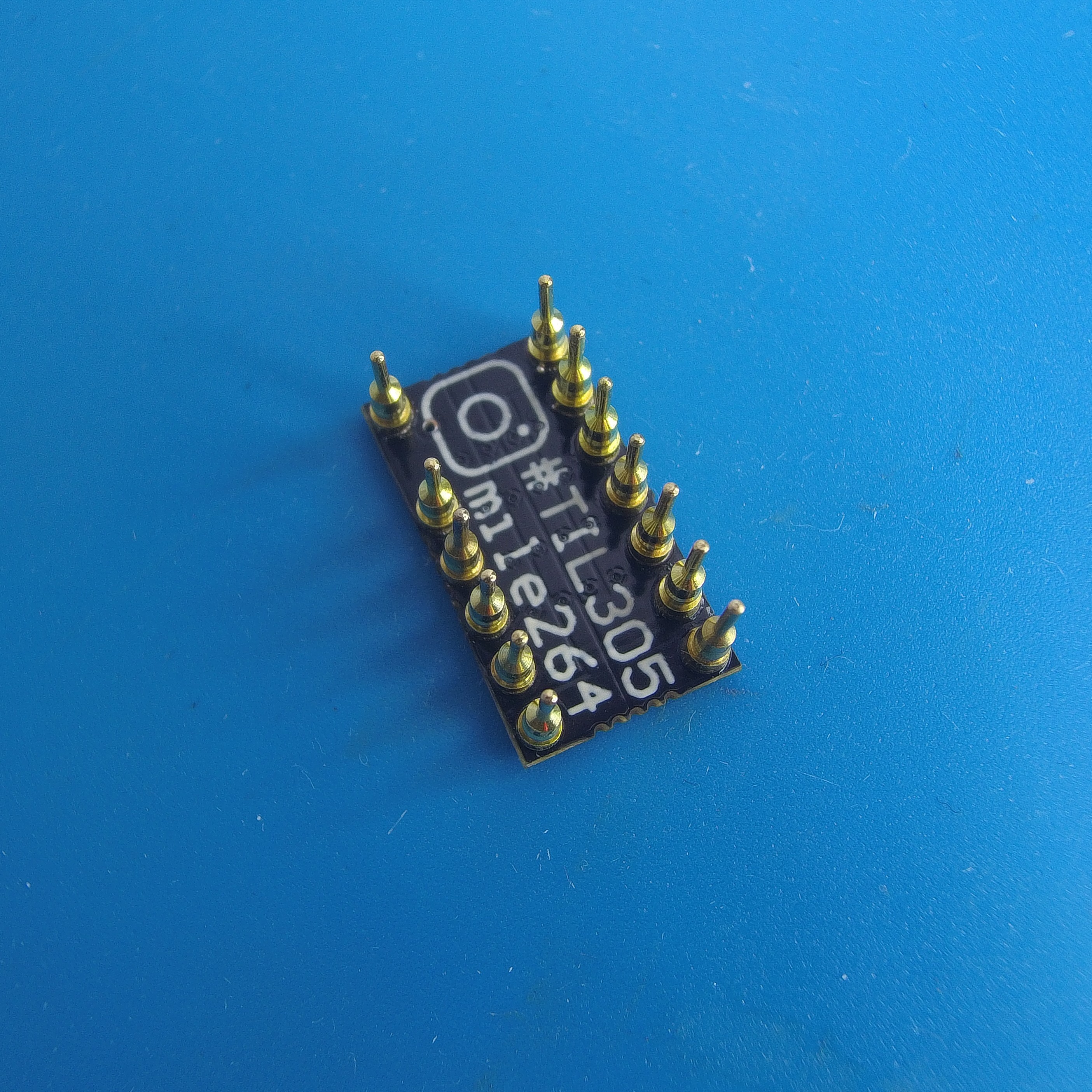
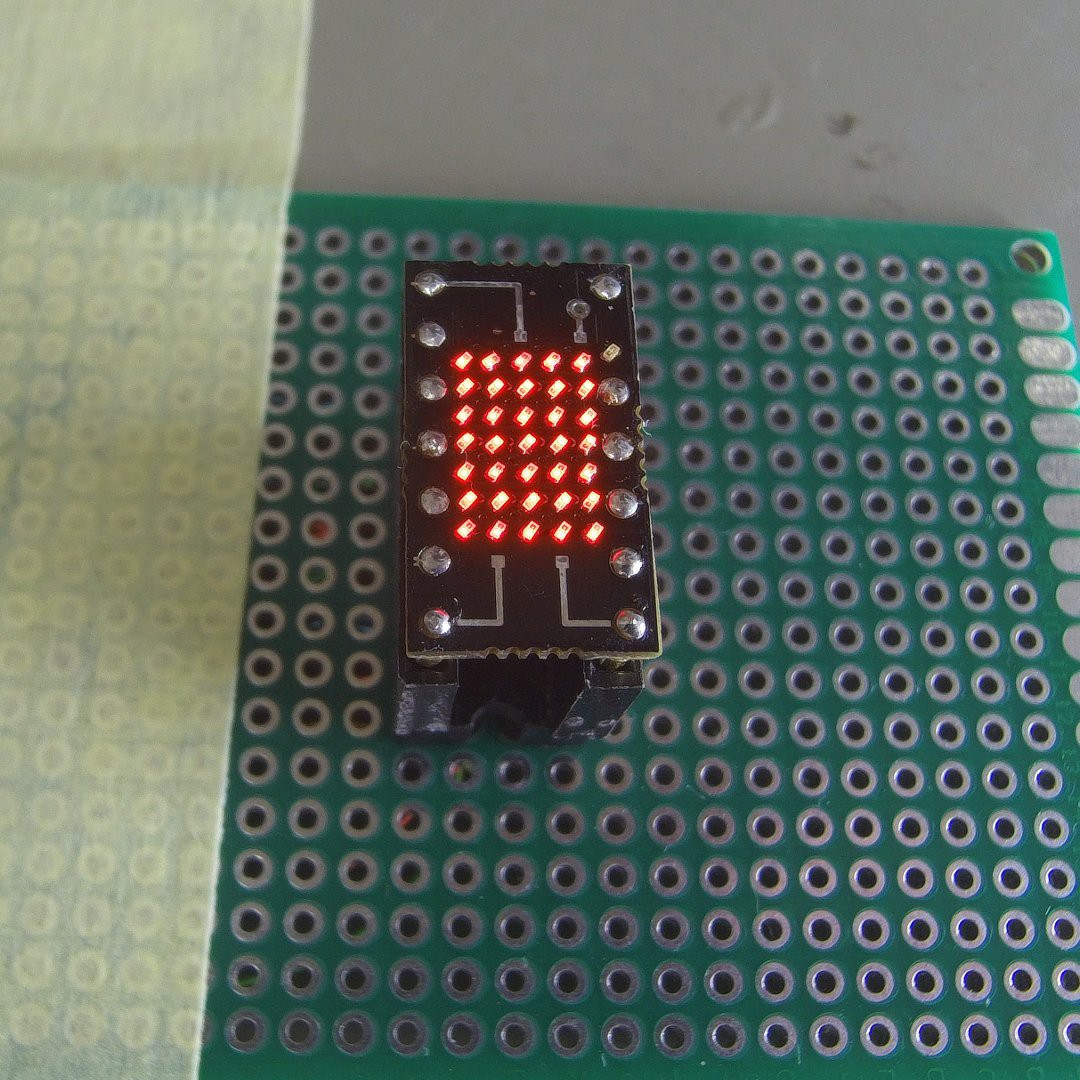
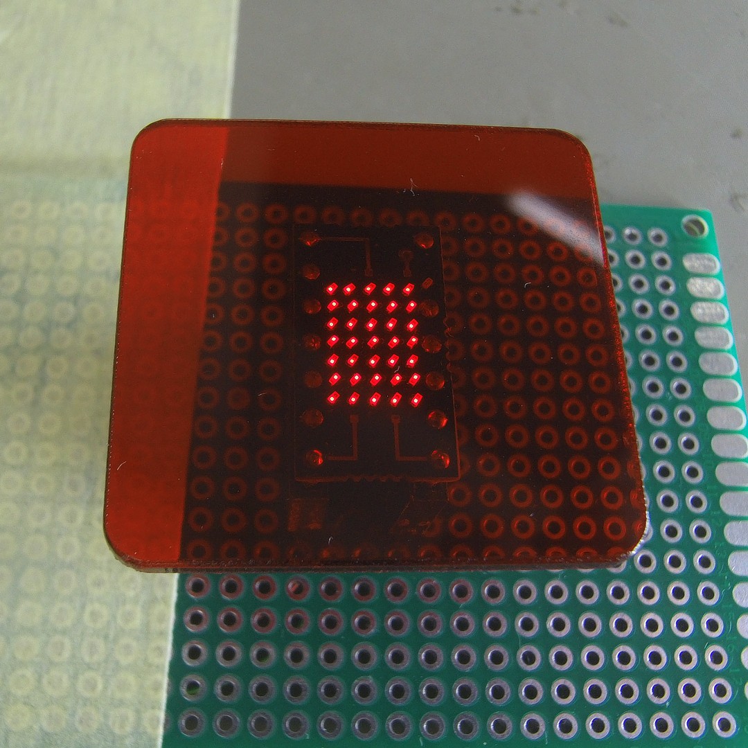
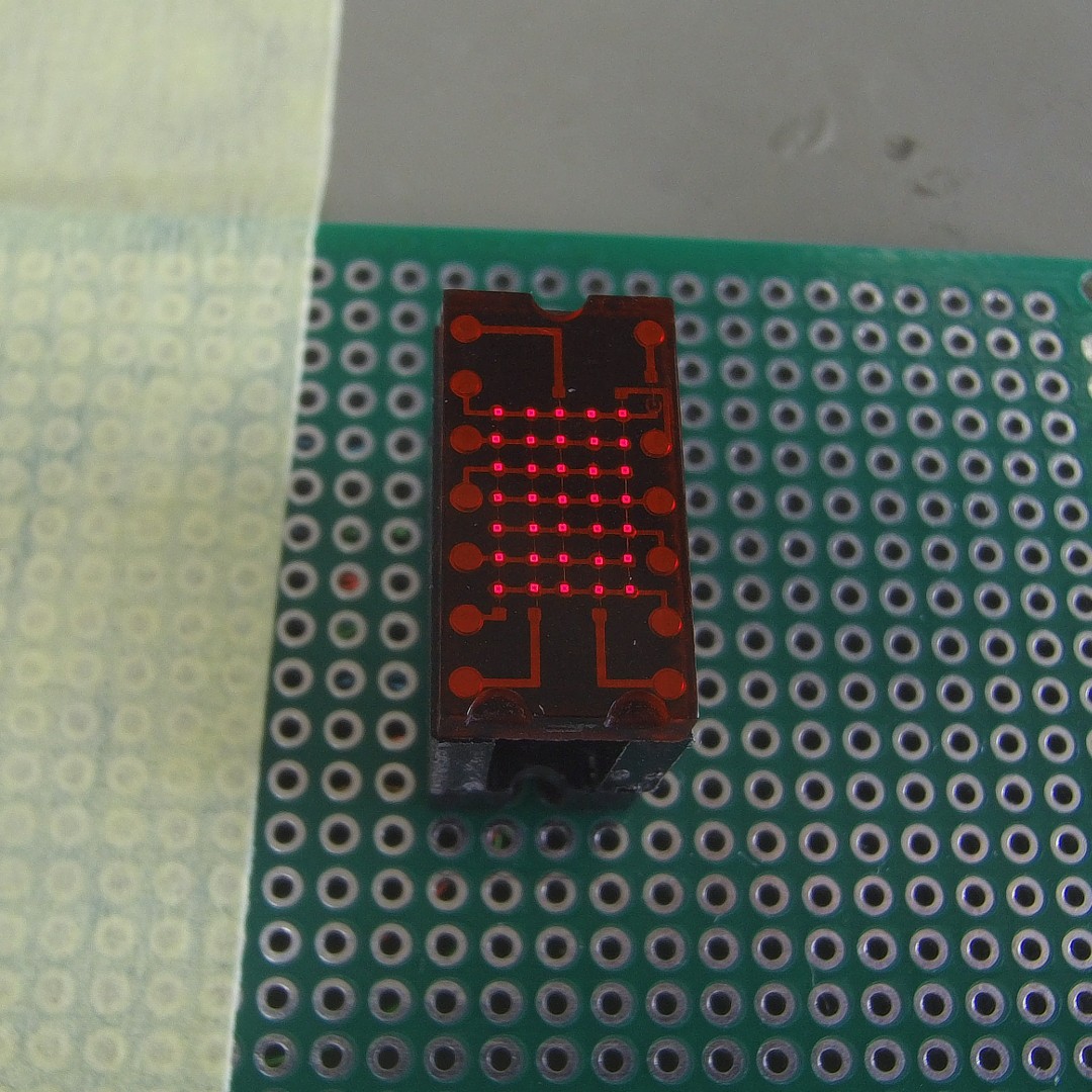
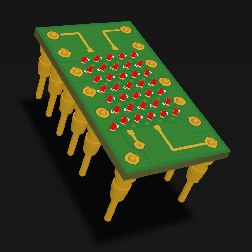
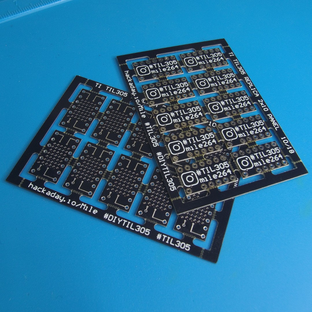
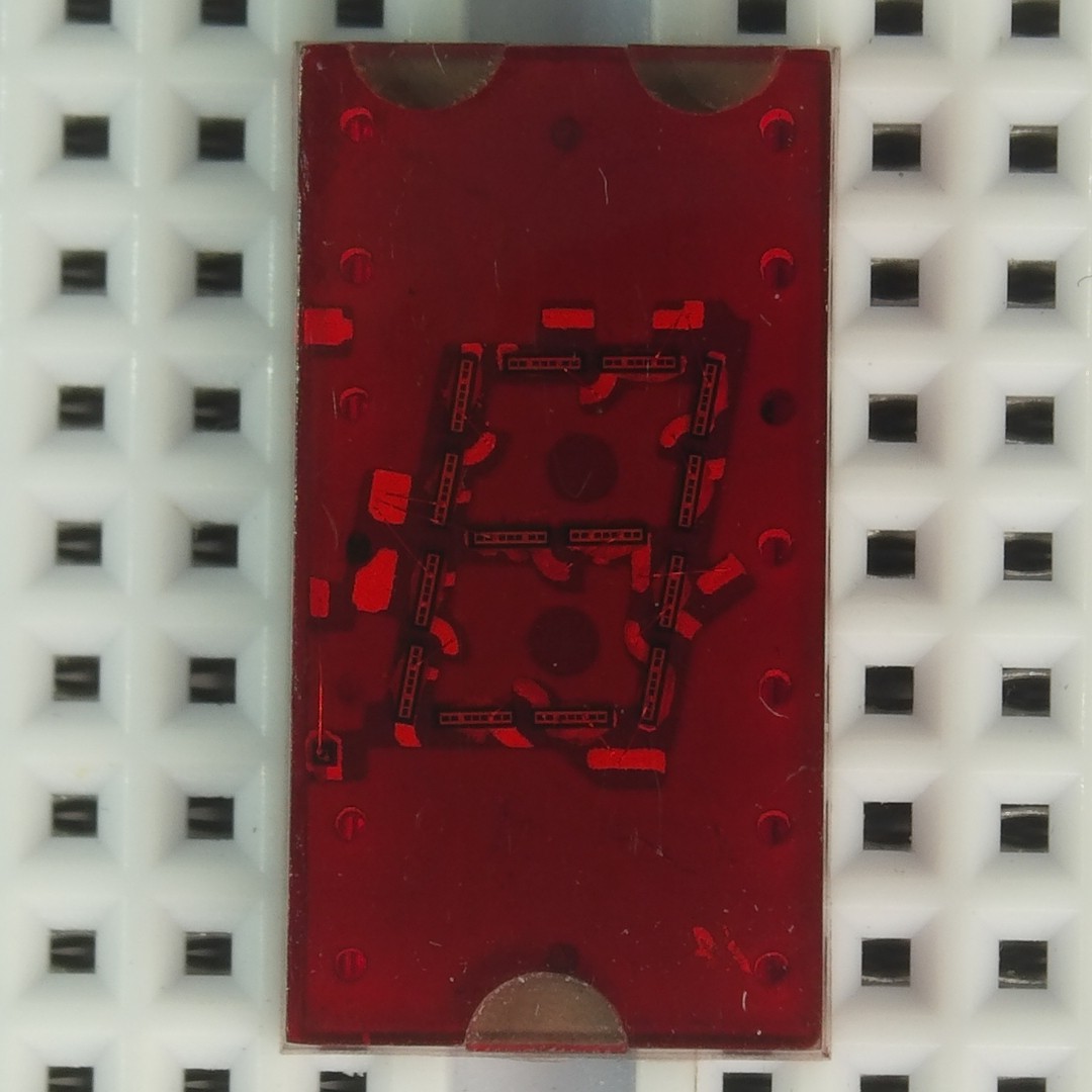
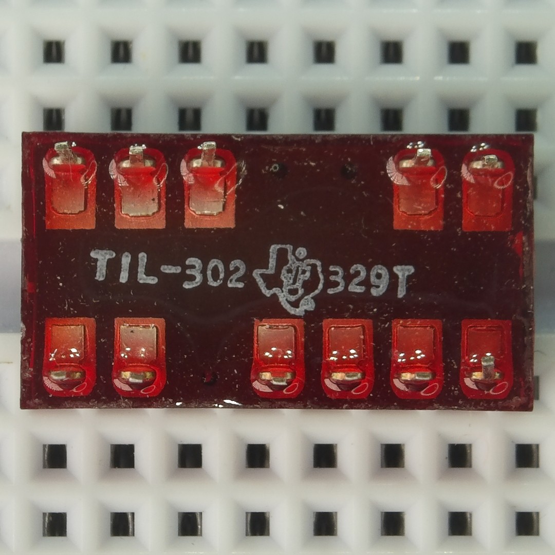
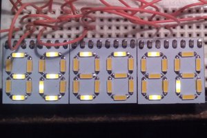
DIYTIL305
DIY replica of TIL305 5x7 matrix display.
 Mile
MileBecome a Hackaday.io member
Already have an account? Log in.
Just one more thing
To make the experience fit your profile, pick a username and tell us what interests you.
Pick an awesome username
hackaday.io/
Your profile's URL: hackaday.io/username. Max 25 alphanumeric characters.
Pick a few interests
Projects that share your interests
People that share your interests


 Yann Guidon / YGDES
 Benchoff
 Cadmium
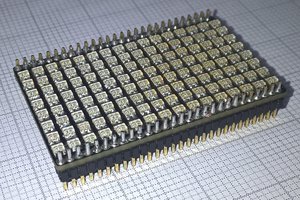
 Alex
Alex
Just wondering what happened to this project?