Close
0%
0%

Open esk8 Remote - v1

Fully open source remote control for common electric skateboards using the NRF24L01+

Public Chat
Similar projects worth following
In June 2018, I bought an electric skateboard. It looked cool in various videos and I was not only eager to learn to ride it but also to replace my car commute to work and the search for the over night parking spot or a parking space during city visits in San Francisco.

The project logs of this project capture my adventure of deep diving into reverse engineering an existing protocol, making it my own and getting a fully custom remote control to work with the majority of cheap Chinese electric skateboards using the NRF24L01+ as it's wireless communication chip.

After buying the Acton Blink Qu4tro, which still is one of the most powerful electric skateboards commercially available, I quickly realized my mistake. I assumed that a relatively small company located in Silicon Valley has enough influence on Chinese motor controller manufacturers to push their own demands through and make a good remote in the process. 

My Qu4tro remote control was of such horrible quality that I decided a change is required to actually enjoy this fantastic piece of leisure equipment - which was otherwise almost impossible:

  • At cruising speeds, the skateboard would show torque wobble and not run at constant velocity at all
  • The remote has trouble communicating when in line of transmission of a wireless communication tower 
  • The remote has terrible mechanical properties, was way too light, felt very cheap and the throttle potentiometer was even pressure sensitive and would accelerate the board when pressed down - not good in stressful situations!
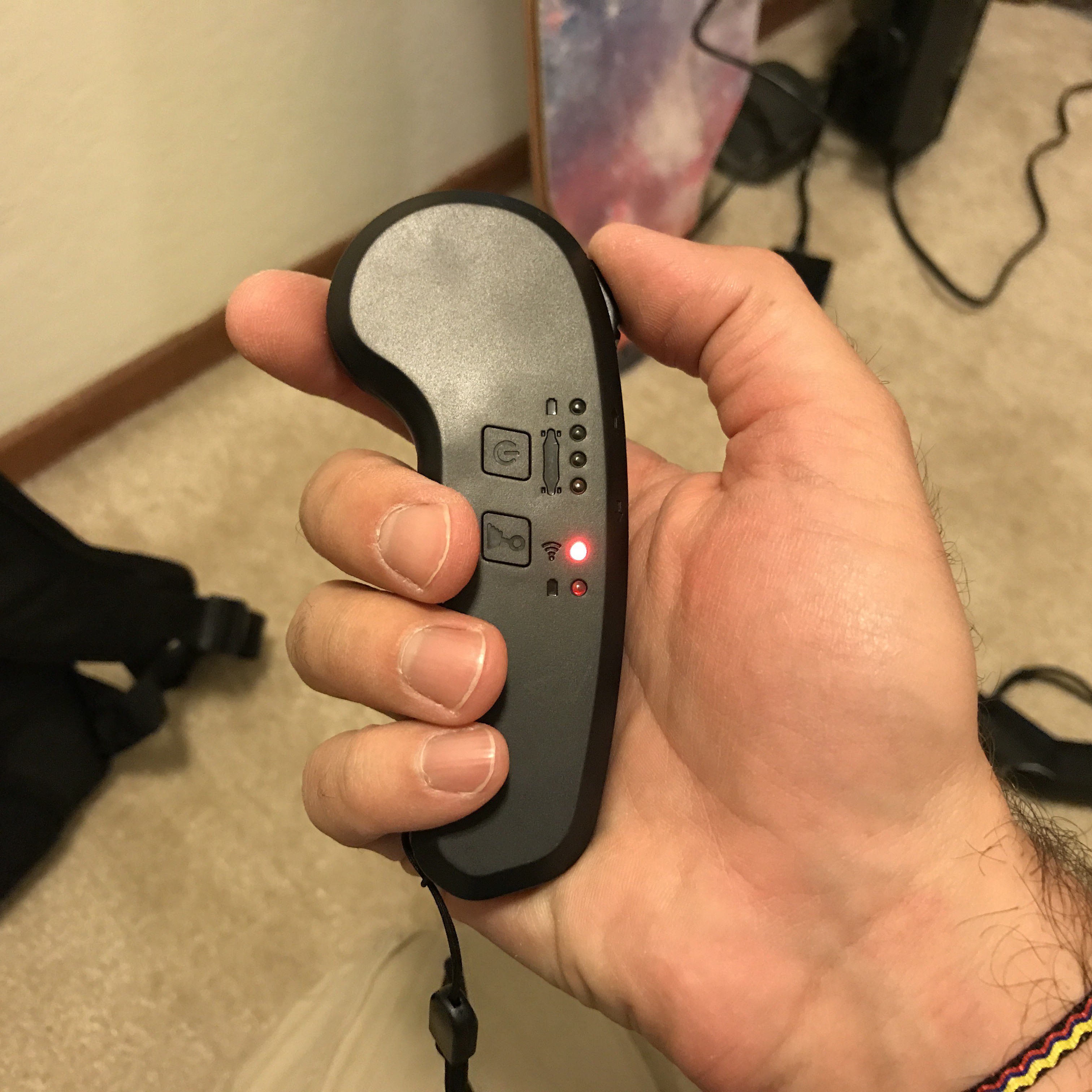
  • The remote had a terrible battery indicator that only blinks in different colors at the bottom - the part that is literally hidden in the palm of your hand!
  • The battery indicator for an EMPTY REMOTE was also just the same blinking LED in three green successive short blinks! (instead of the long green blinks when the board itself is fully charged!!)
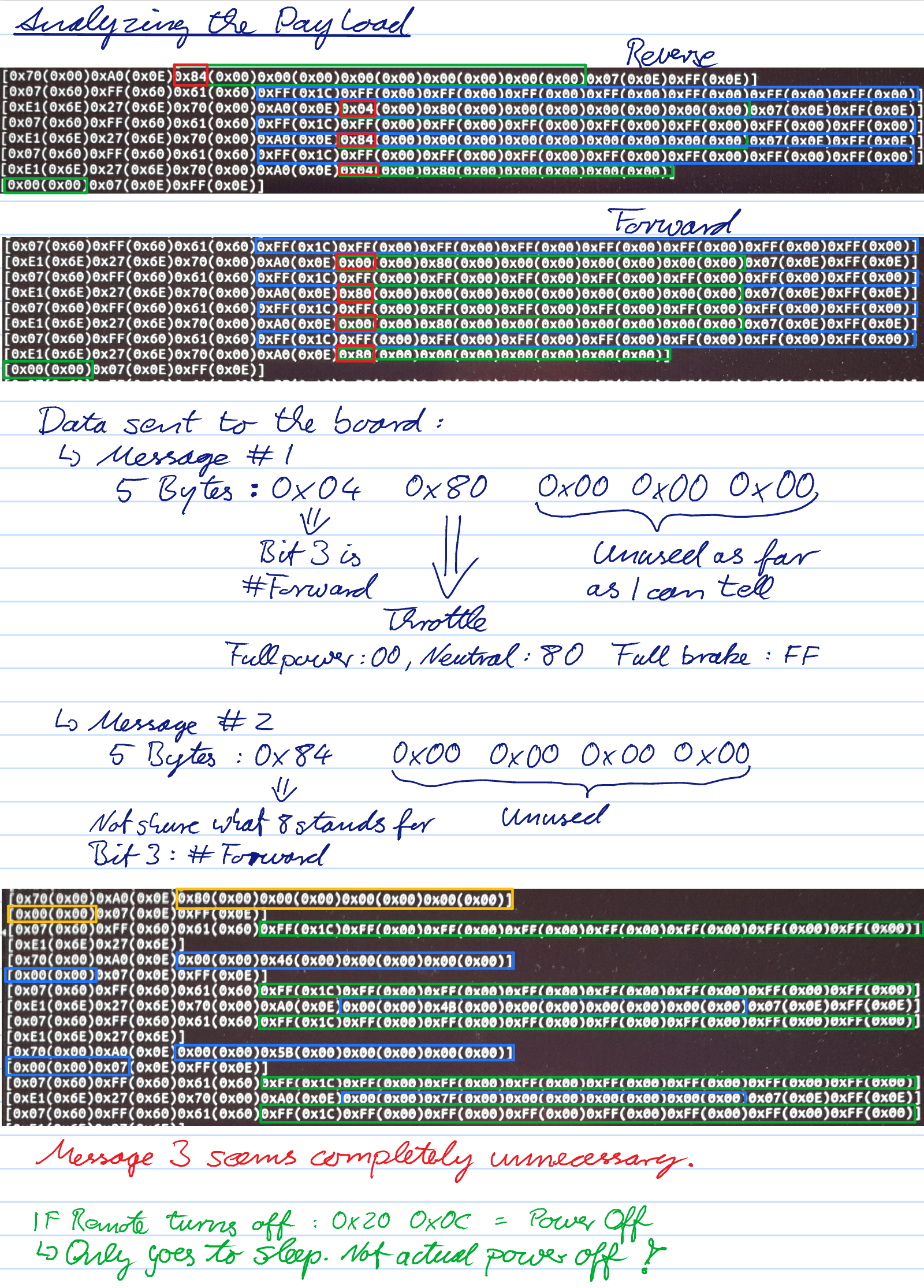
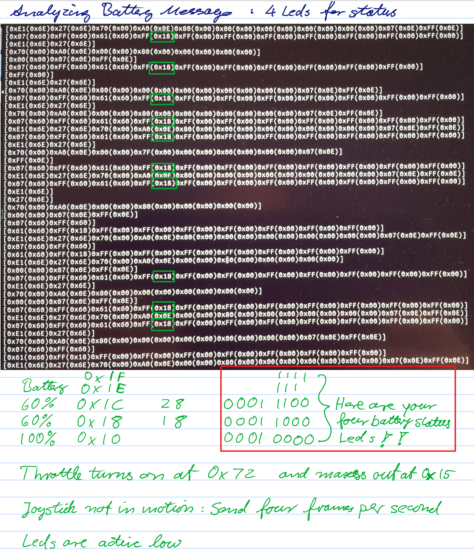
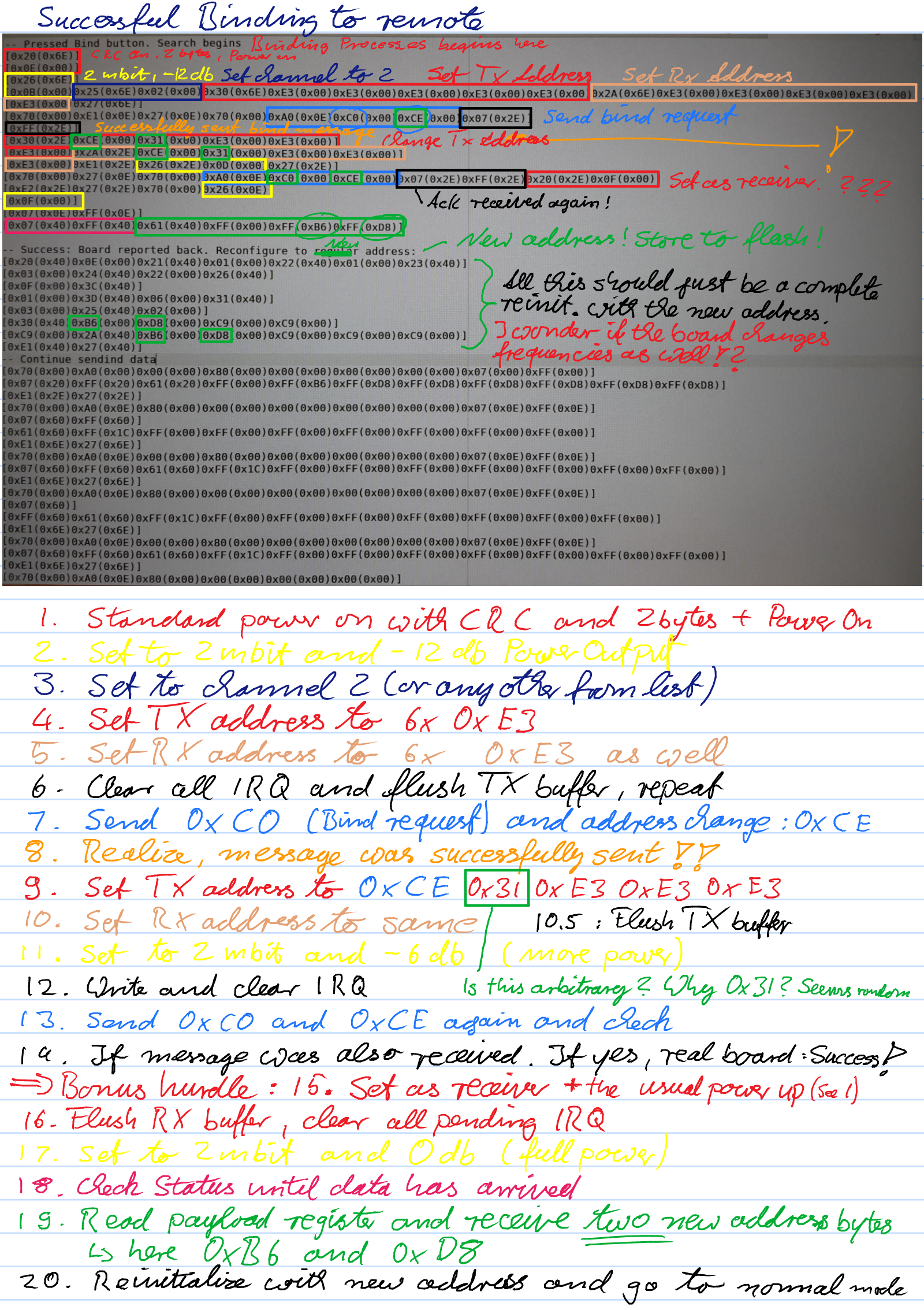
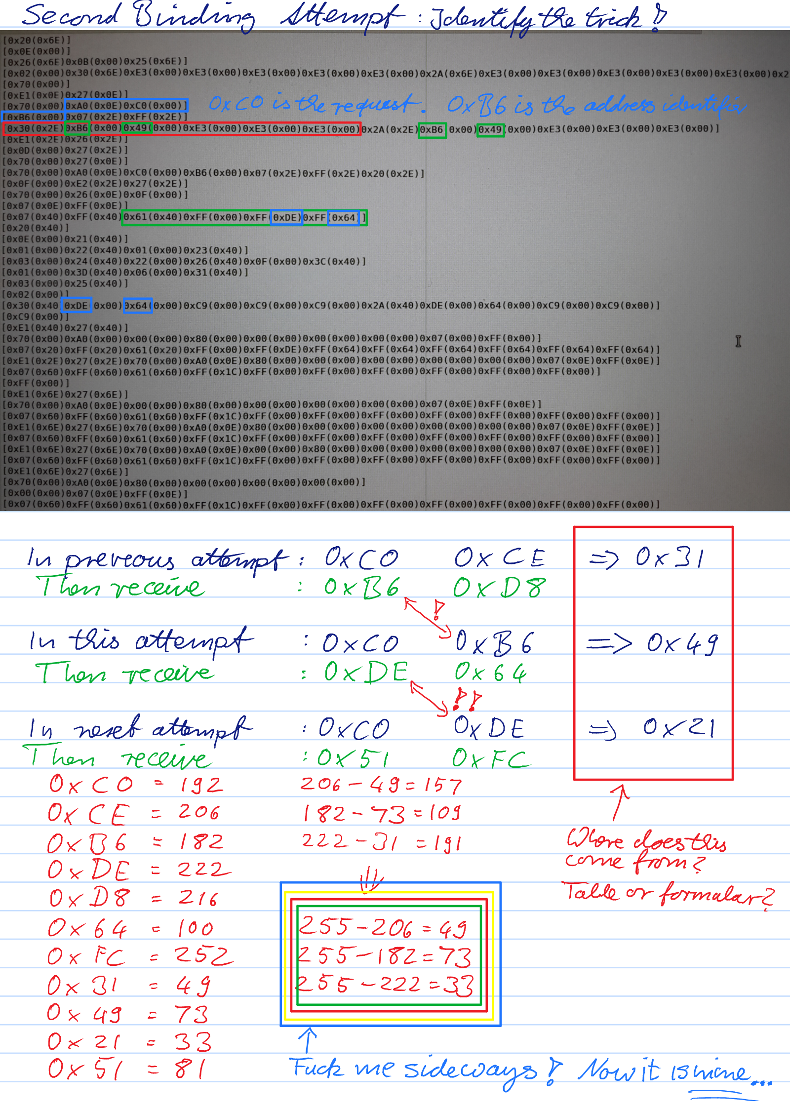
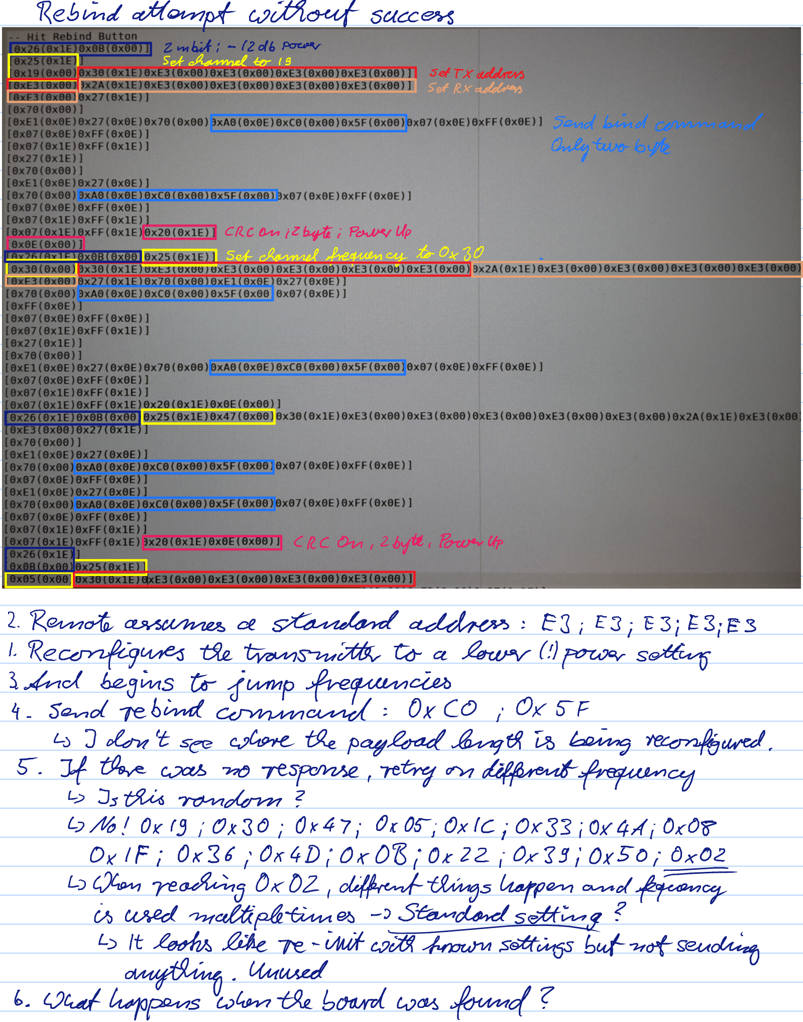
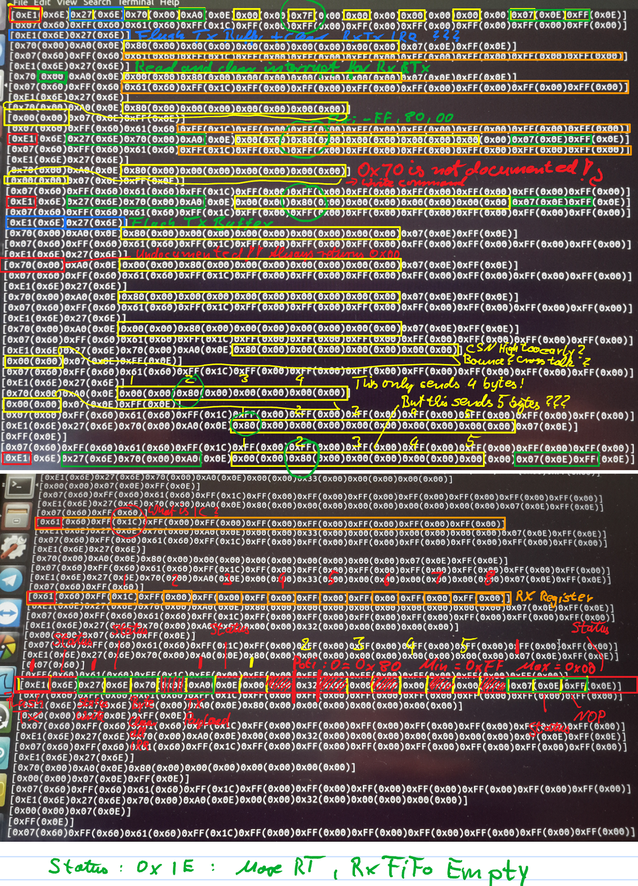
  • There are other major issues, that I will mention below when I go into detail about the communication protocol used

In my arrogance and wild feverish dreams I loudly announced my goal to completely reverse engineer this skateboard and take over control of the various bits and pieces. Something I thought I could probably do but had never really done before in great detail on a complex system like this.

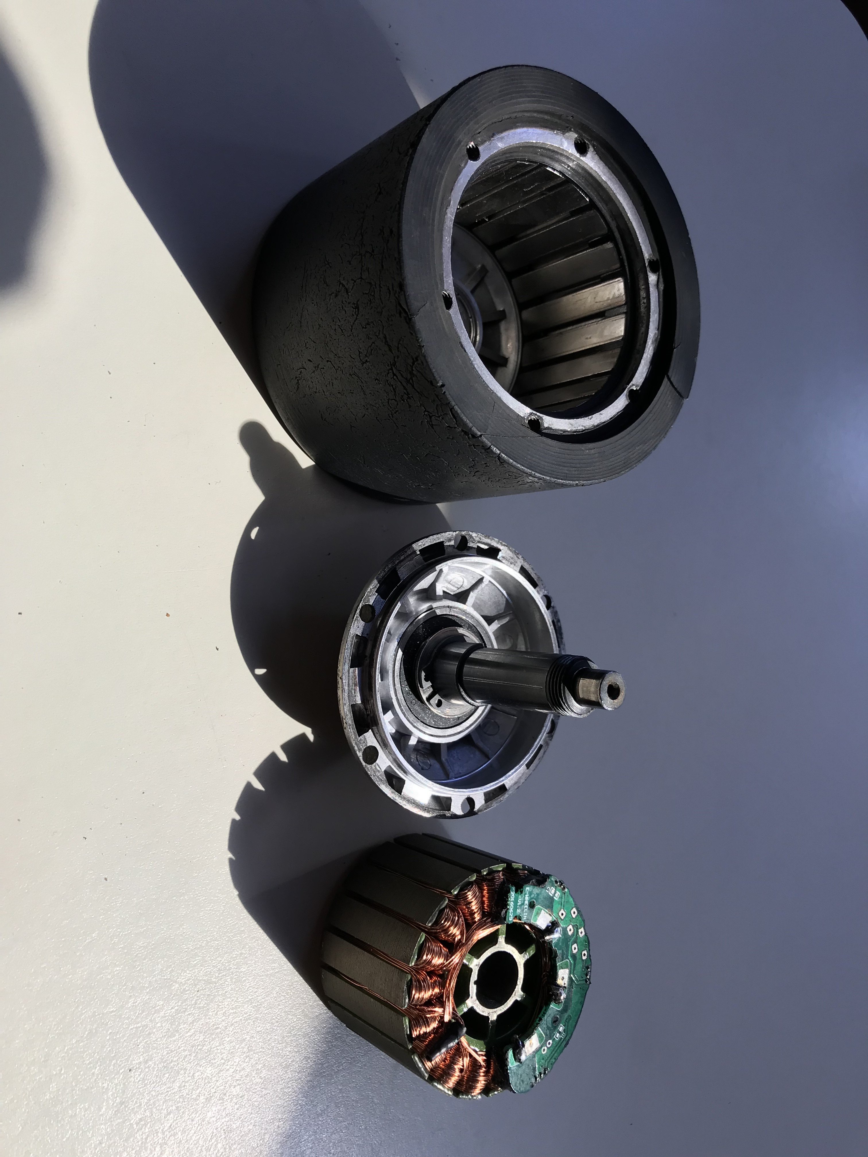
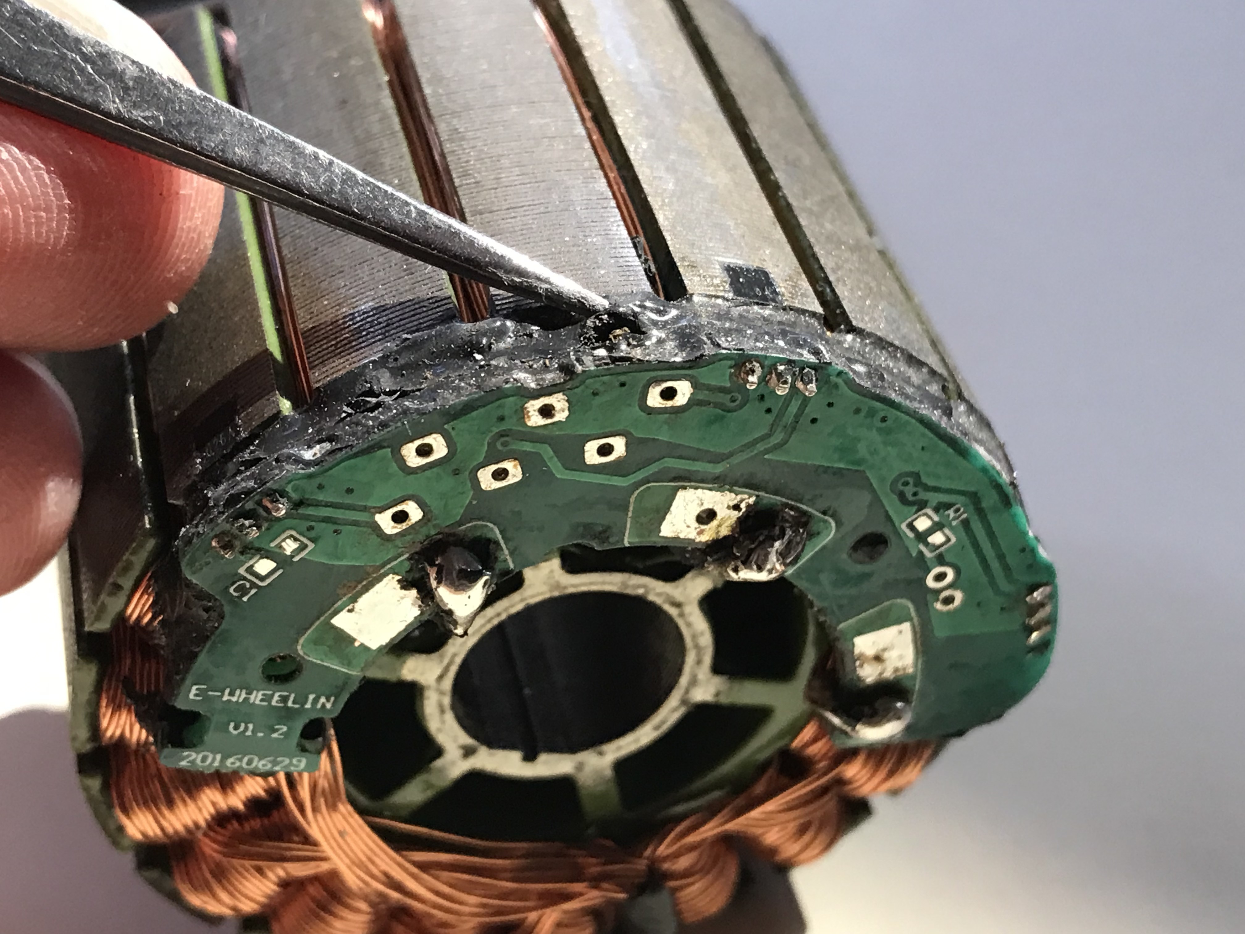
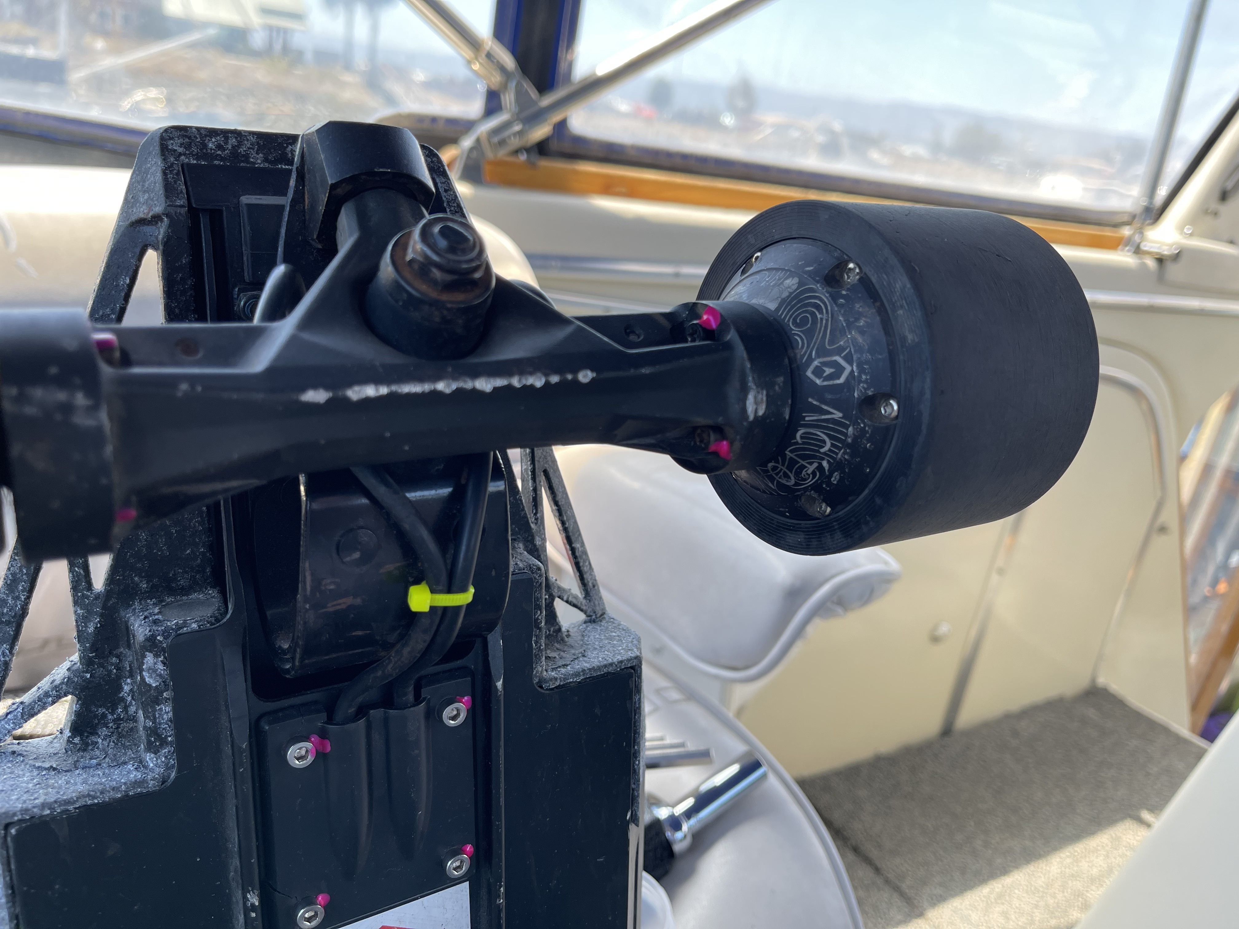
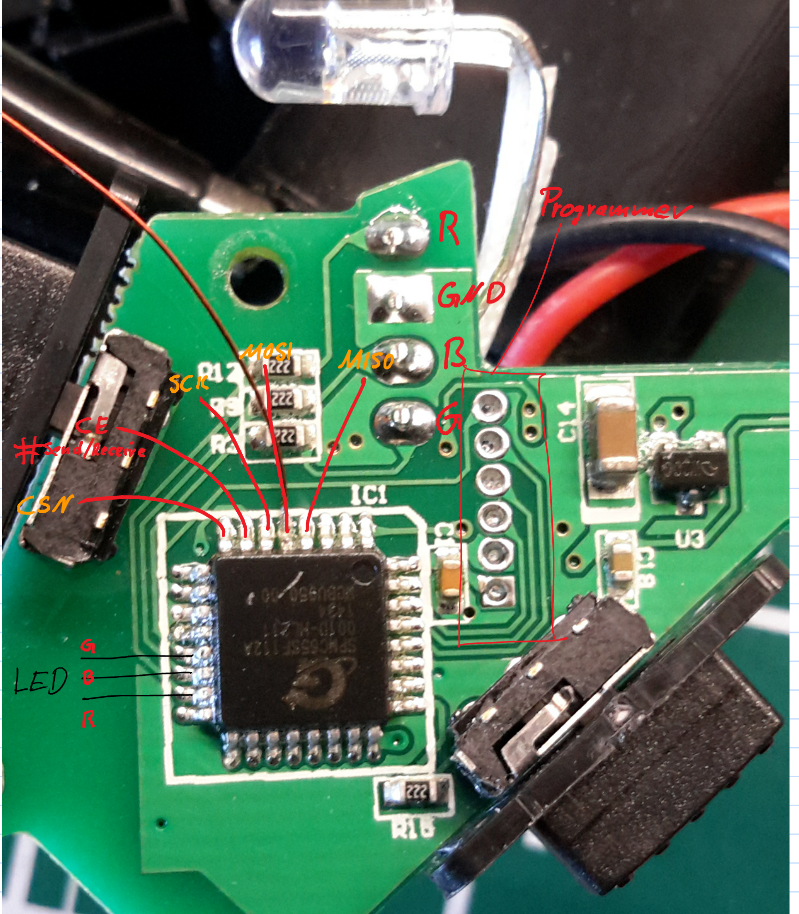
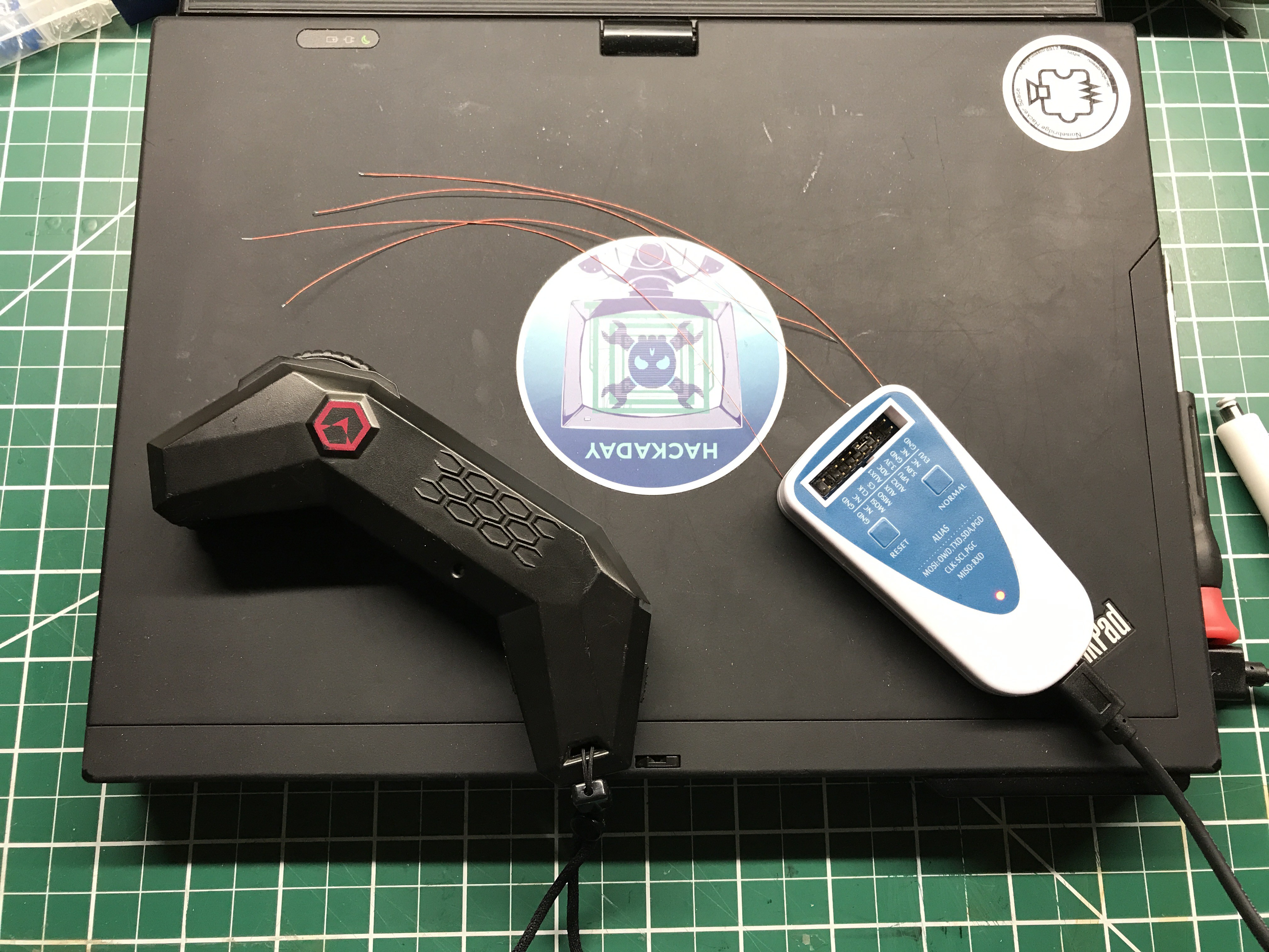
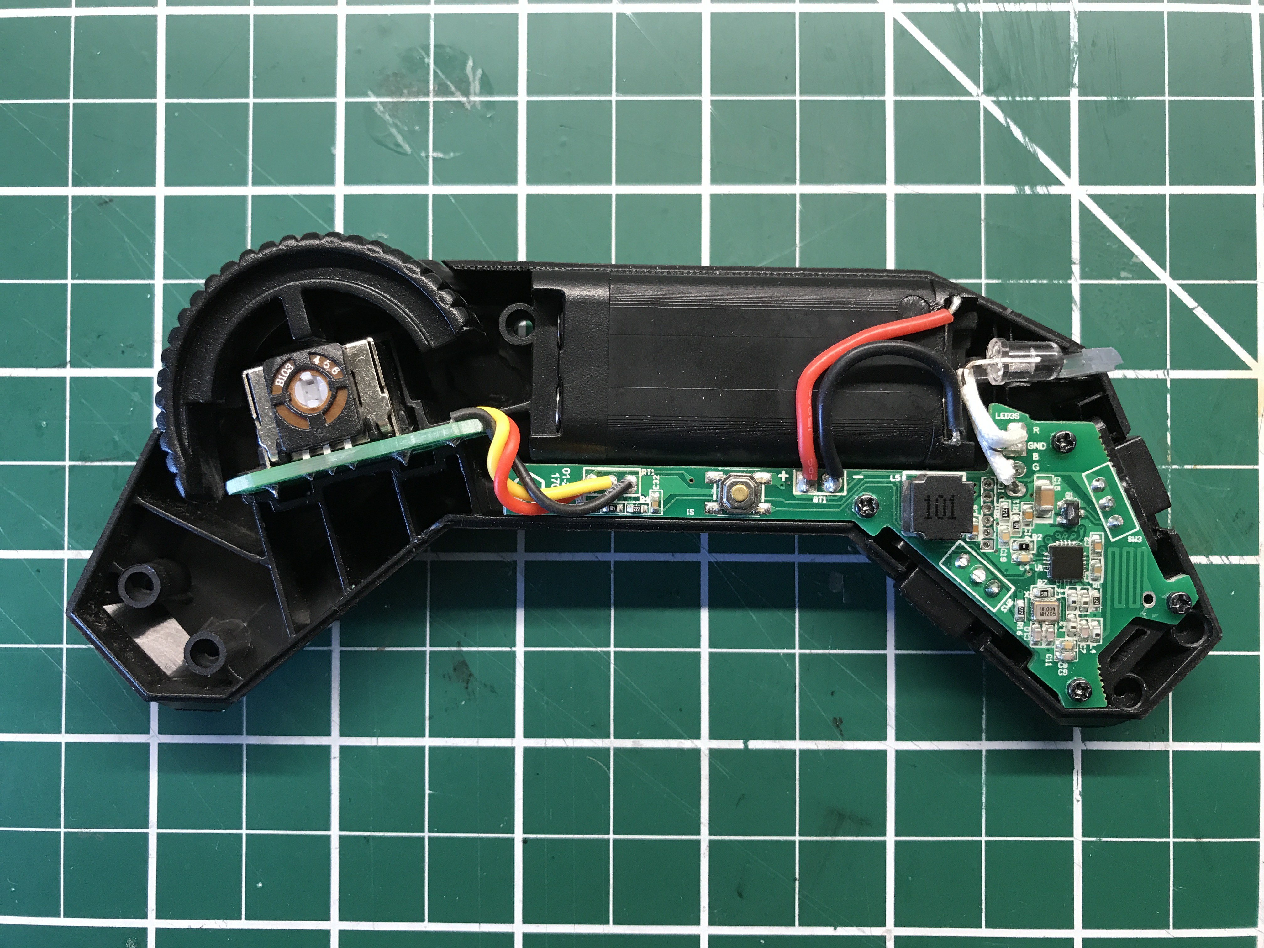
About five weeks after my public announcement, I had enough and took the remote and board apart to look at everything, take a ton of pictures and start with searching for chip datasheets. With only two hits, I was pretty disappointed to realize, I'll not be able to take over these Chinese micro processors that are produced by the thousands and have absolutely no description at all!

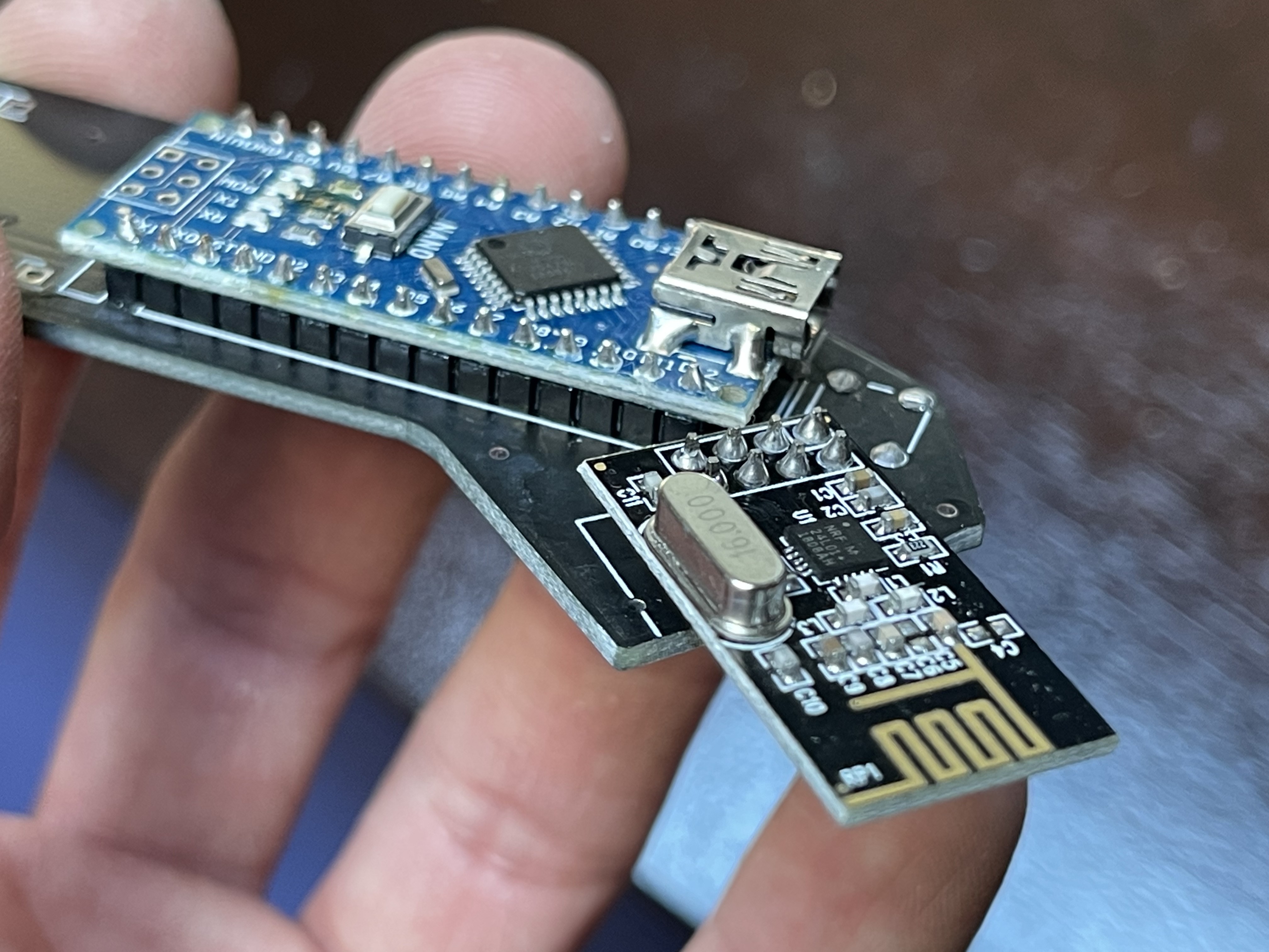
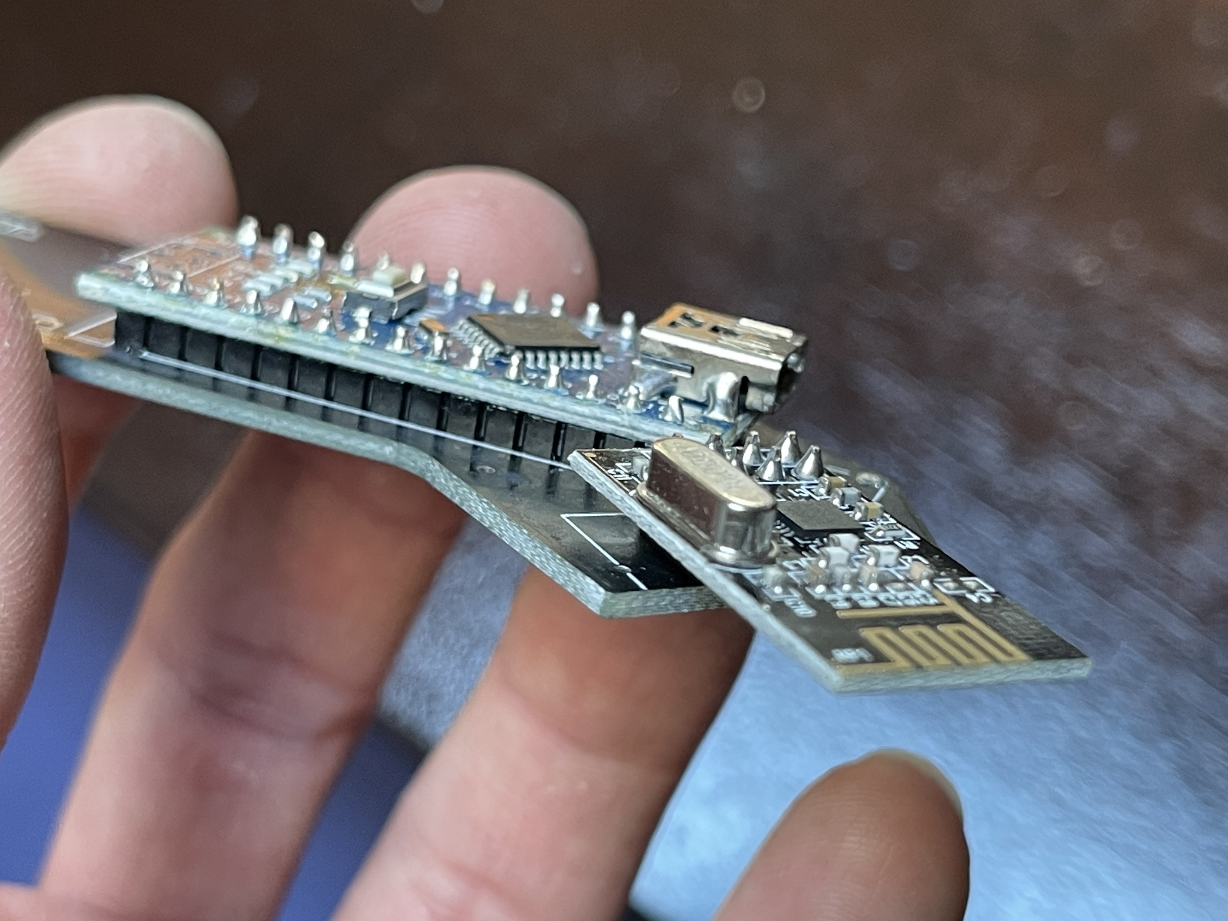
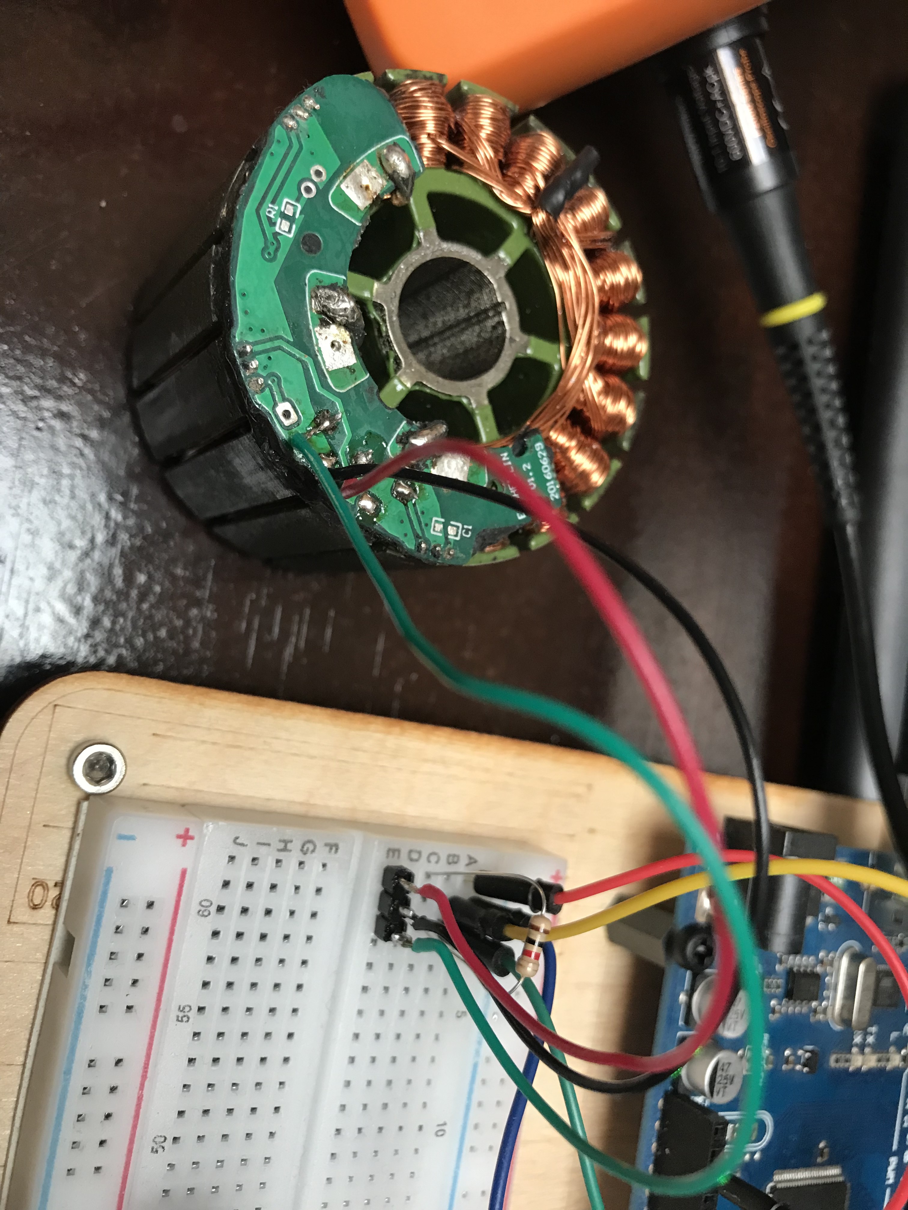
However, I had two very dominant hits, that made this process possible:

  • The wireless communication chip NRF24L01+ used in both, the remote as wel as the receiving end on the board
  • The wireless bluetooth chip used for communication with the smartphone app

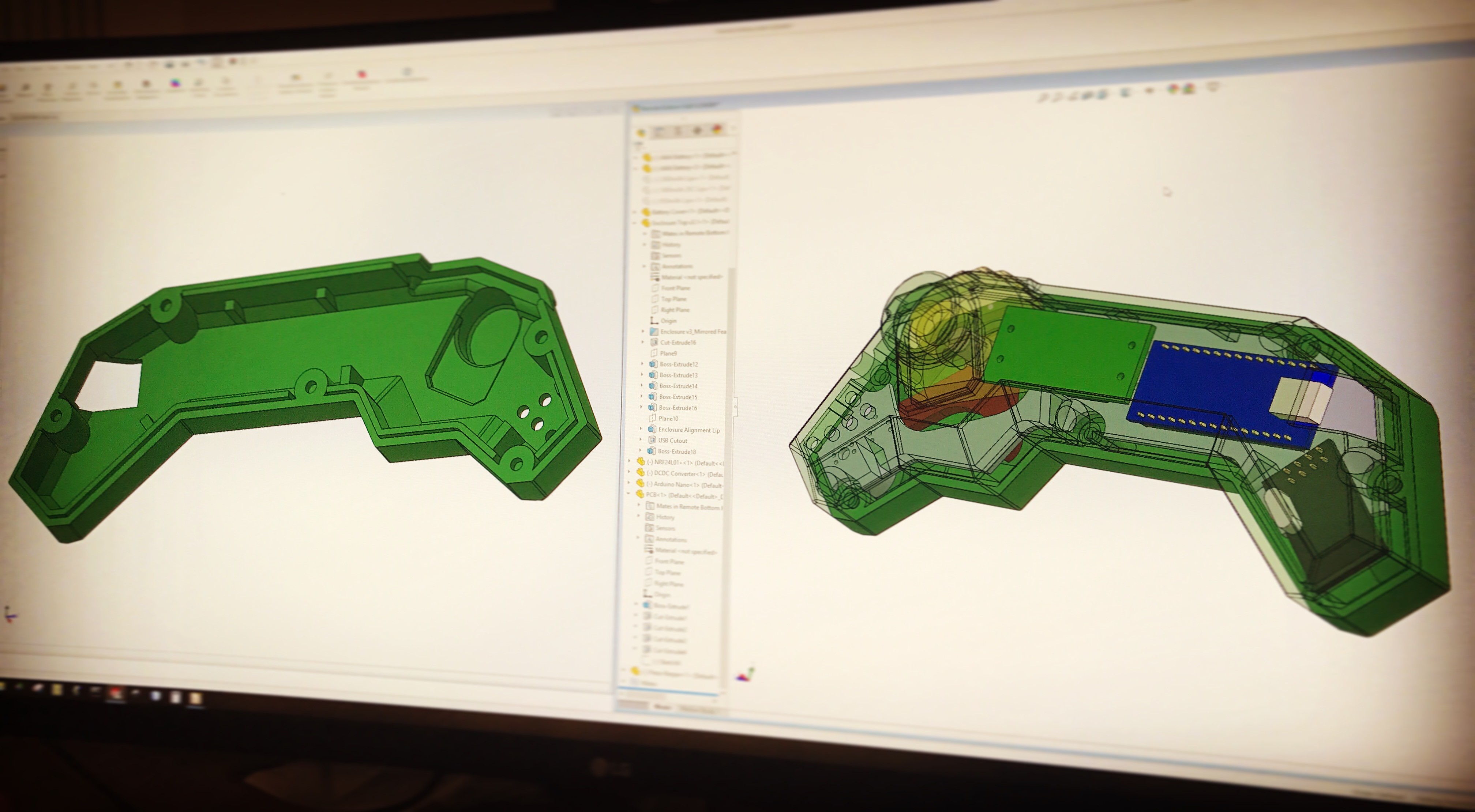
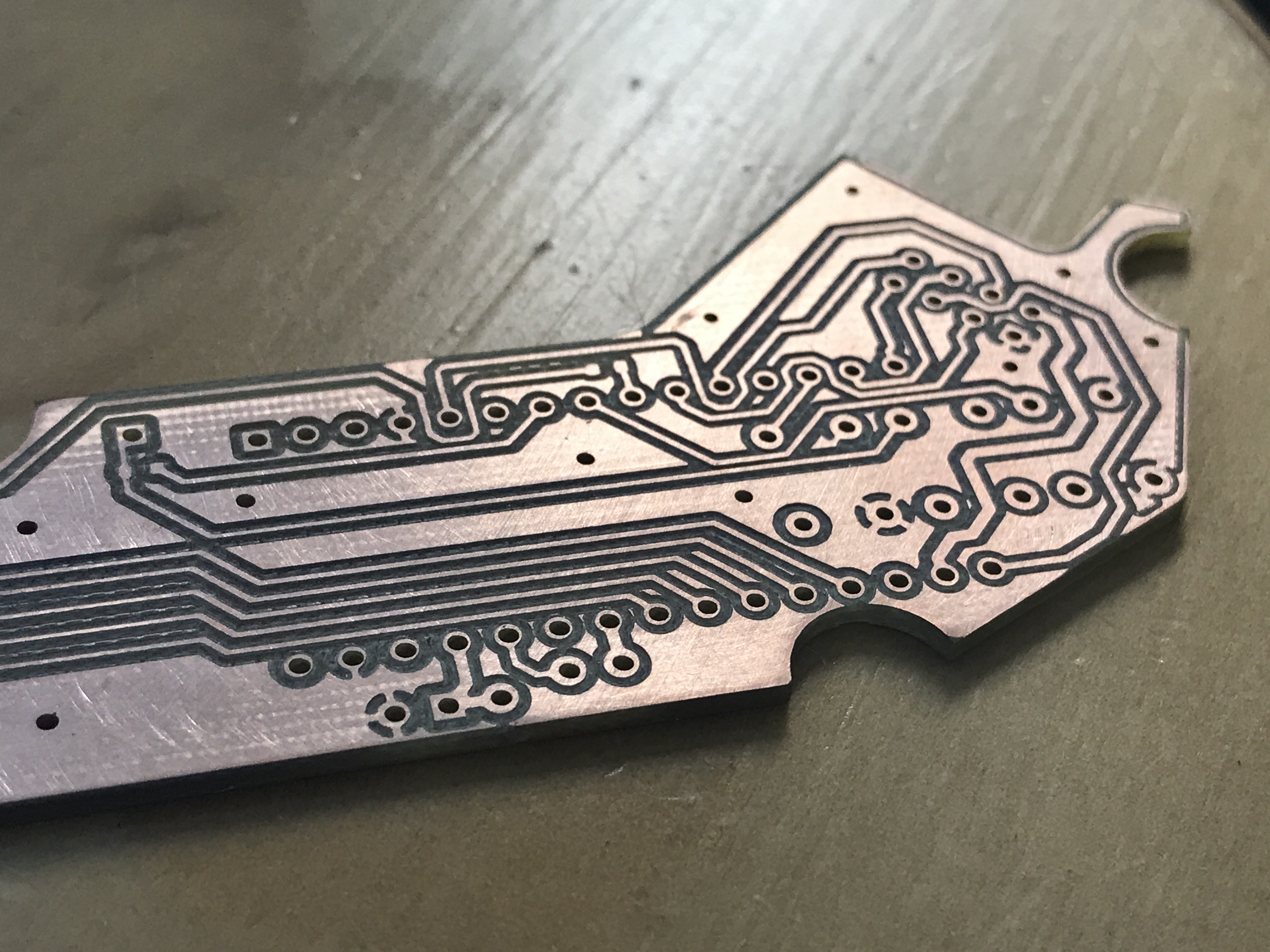
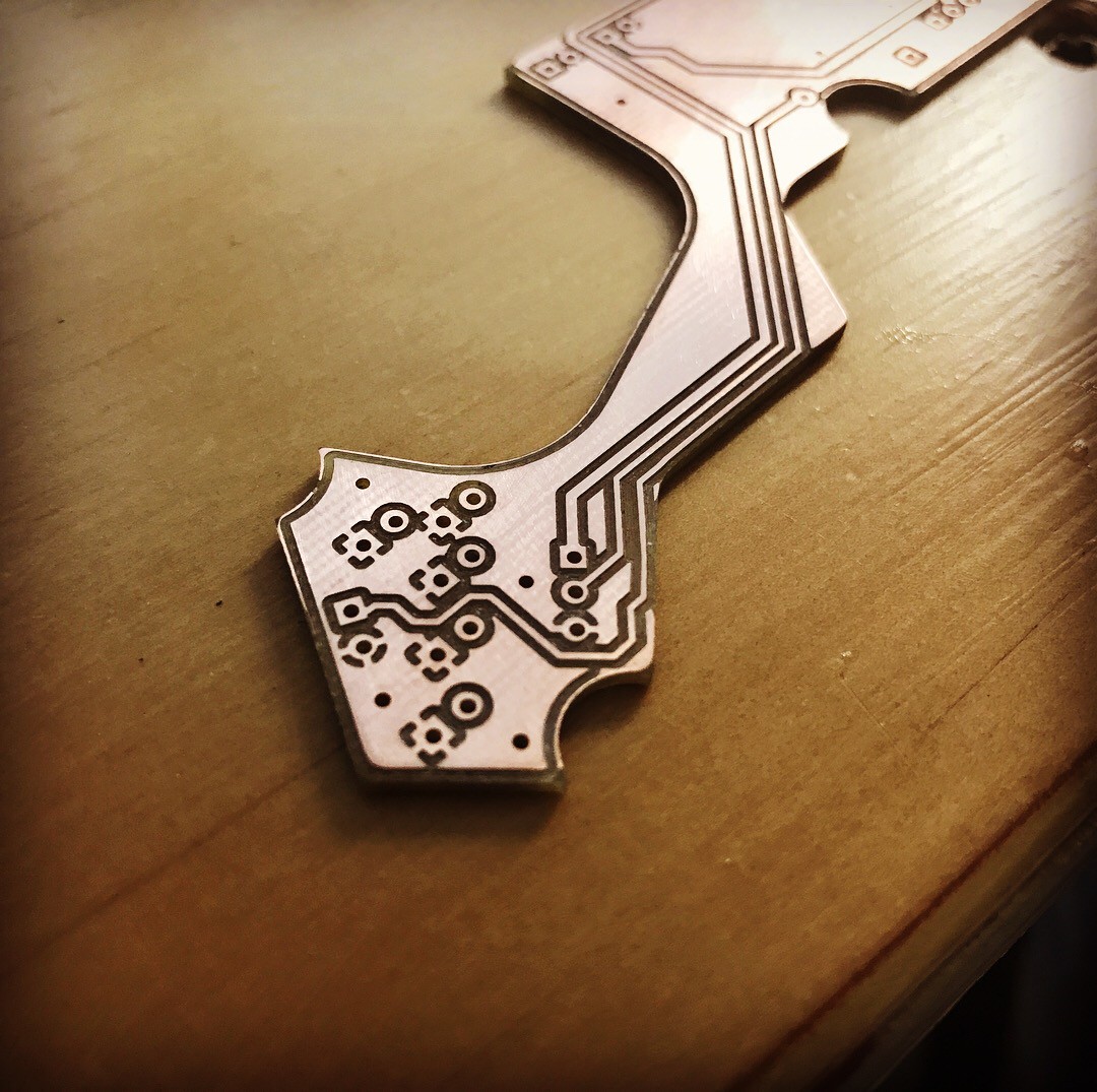
Apart from learning a lot during this process, I managed to reverse engineer the entire wireless communication protocol, write code around it to handle pairing and general communication, design my own custom electronics, enclosure and throttle mechanism and bring it all together using my PCB mill as well as my 3D printer.
This logbook is an aftermath of the steps I took and the success and fun I had doing this project.   

The project documentation is work in progress even though version 1 of this remote works very well and already has 200 miles on its back without a single failure or disconnect.

The STL files can be found on my Thingiverse project page: https://www.thingiverse.com/thing:3273537

The code can be found in my GitHub repository: https://github.com/McNugget6750/Open-esk8-Remote

  • Version 1.5! After three solid years of version 1!

    Timo Birnschein08/01/2021 at 16:29 0 comments

    PLA is a great material to print with! The quality can be as good as you want, the supports are reasonably easy to remove, the layers adhere to each other extremely well, and when it cracks, it usually brakes similar to real plastic. Cheap plastic but at least like real cheap plastic.

    So after three years of driving around with my original design with several software changes and updates, the hardware was still pretty much completely unchanged.

    However, I had a pretty big crash in 2018 and the remote took a pretty brutal hit with my entire body weight being smashed into the remote. To my big surprise, it took the hit well and even complained that it wasn't connected to the board anymore when I was able to perceive my surroundings again.

    At that point, it was pretty much cracked everywhere, but specifically at the bottom. At first, a few drops of CA glue solved the issue for me and I continued to drive this thing. However, when I left it outside baking in the sun for an entire day, pretty much everything cracked and warped and deformed. It was time for a revision!

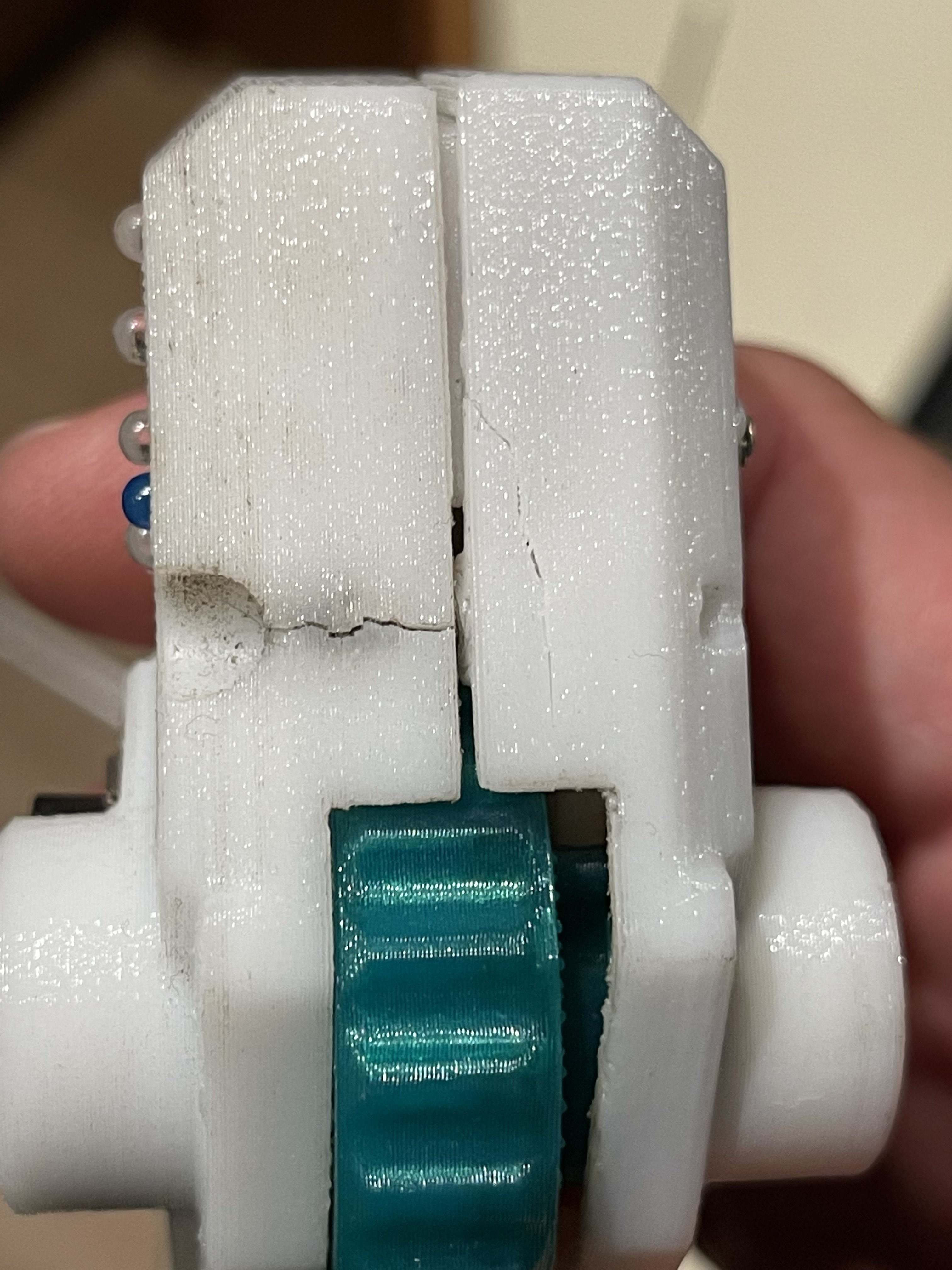
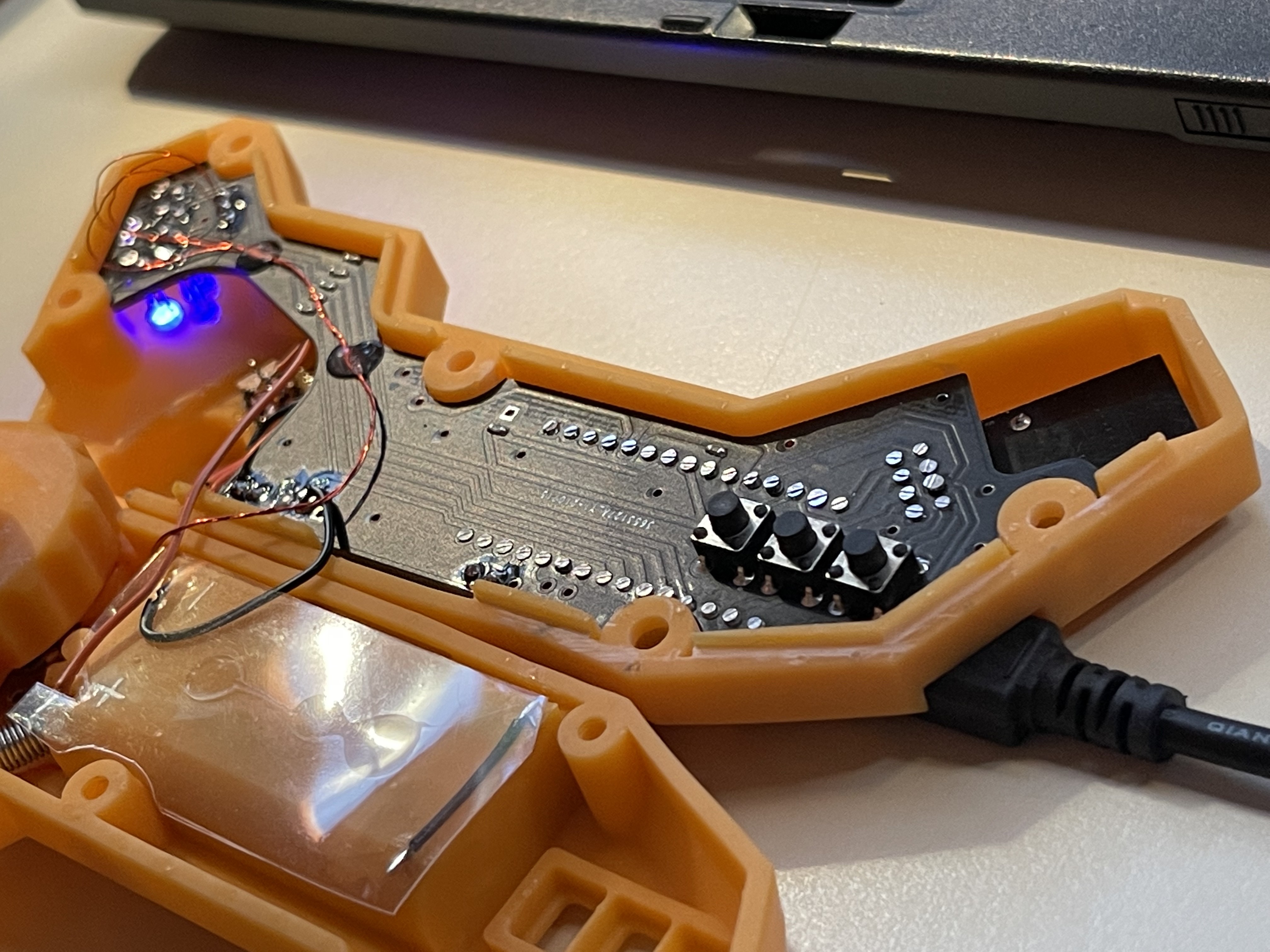
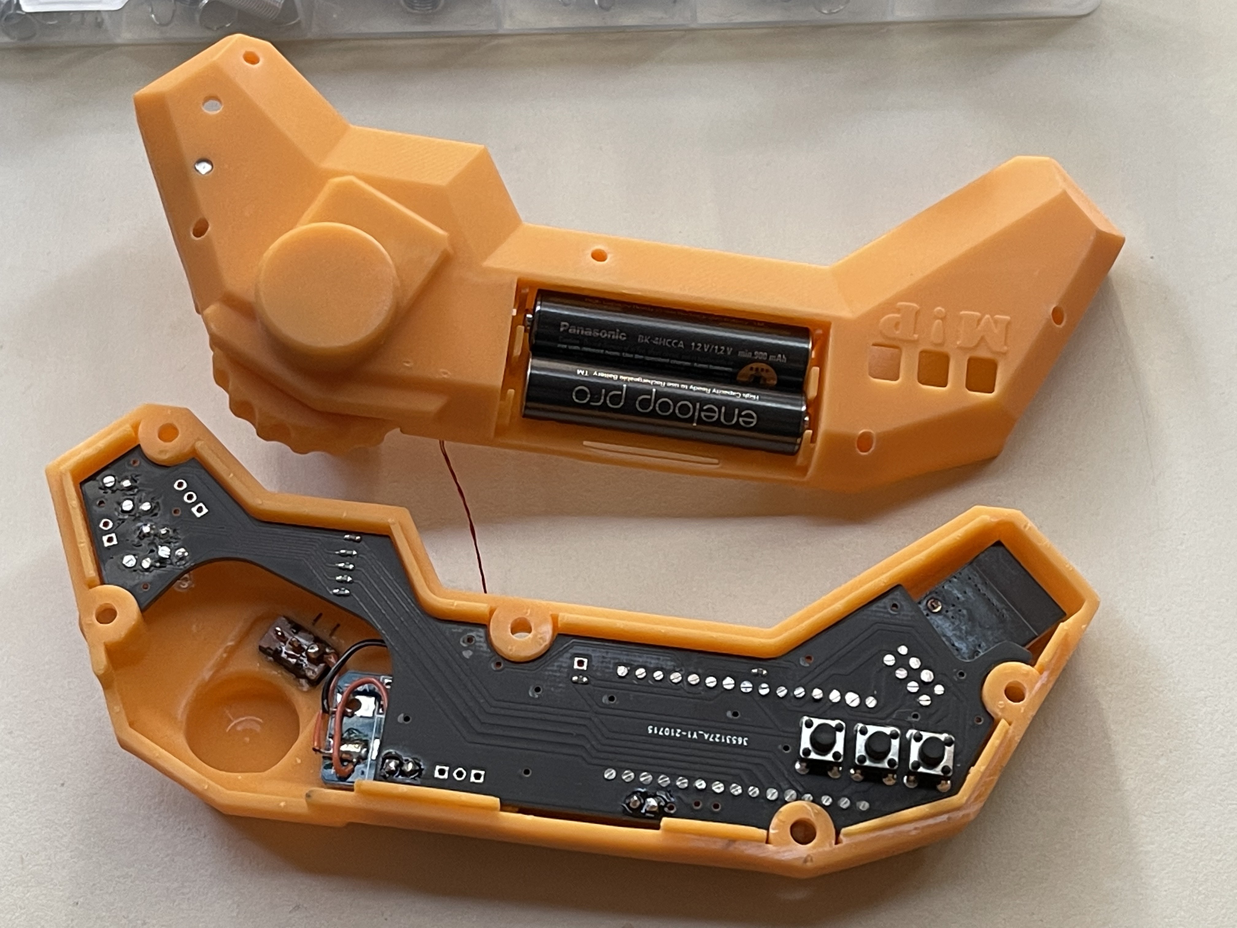
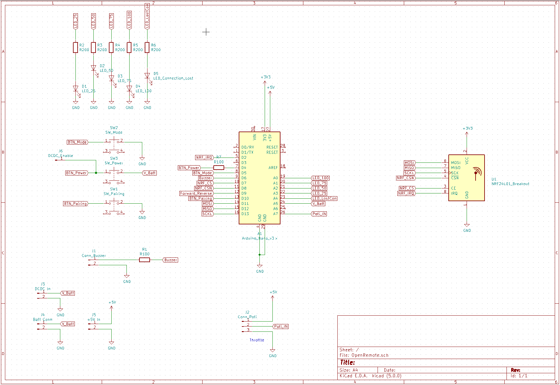
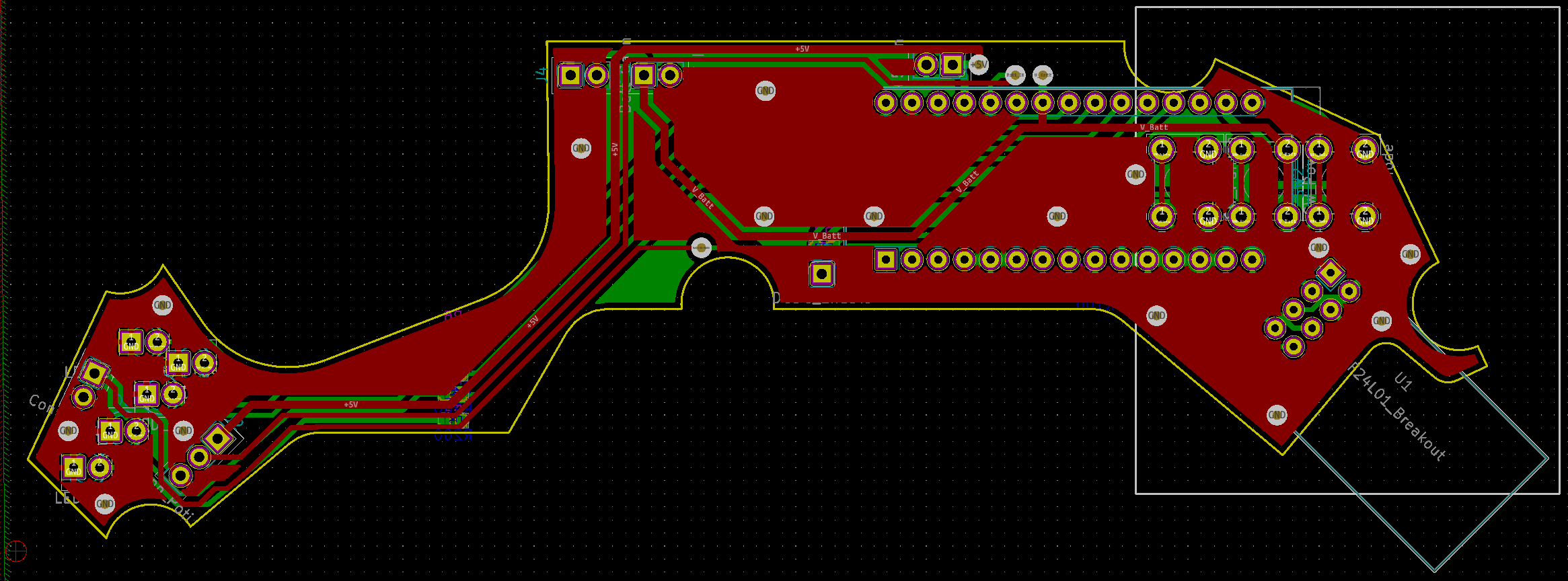
    I decided to add some minor updates to the PCB and change a few wires around but nothing major changed. All pin assignments are still the same as I wanted to maintain compatibility to my previous version.

    However, what I did want to change, though, was the PCB itself. Even though my two home made boards worked really well for their entire life, I felt like testing JLCPCB for the first time. So I exported my GERBER production files and got a quote.

    I could not believe my eyes when I saw that 5 boards at JLC would cost me $9.85 SHIPPED! What on earth. I didn't even care about the 18 days until the boards would arrive, I just wanted to see if these boards are any good.

    In the meantime I tried printing my enclosure on my Anycubic Photon which I dramatically underutilized since I bought it a few years ago. A shame really. The prints have some issues with warping and it definitely requires some finesse to get prints to stick to the build plate, to come out reasonably un-warped, and also the walls are thicker. So I needed to make modifications to my design files to accommodate for that. Unfortunately, the slicer is not as smart as Cura or KISSlicer to thin-out walls (inset) automatically based on some printer specific calibration values.

    The prints took about 24h each since these pieces are really tall and barely fit into the printer at all. Also, the orange, in stark contrast to the translucent green the printer came with, needs a lot longer exposure times, a heated chamber, and lots of massaging to come out right. In the end, I tried to squeeze my development board into this and.... it was a bit tight. Very tight. But nothing a bit of sanding the PCB couldn't fix so I decided to stick with these:

    About 17 days later, I received a nicely packaged set of boards from China and boy did they look great!

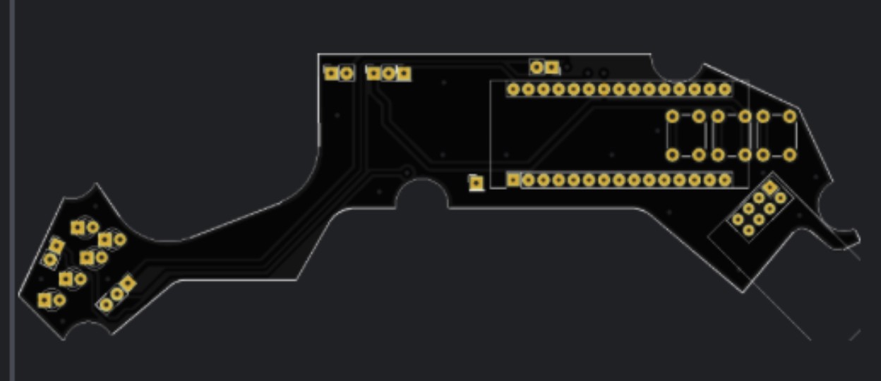
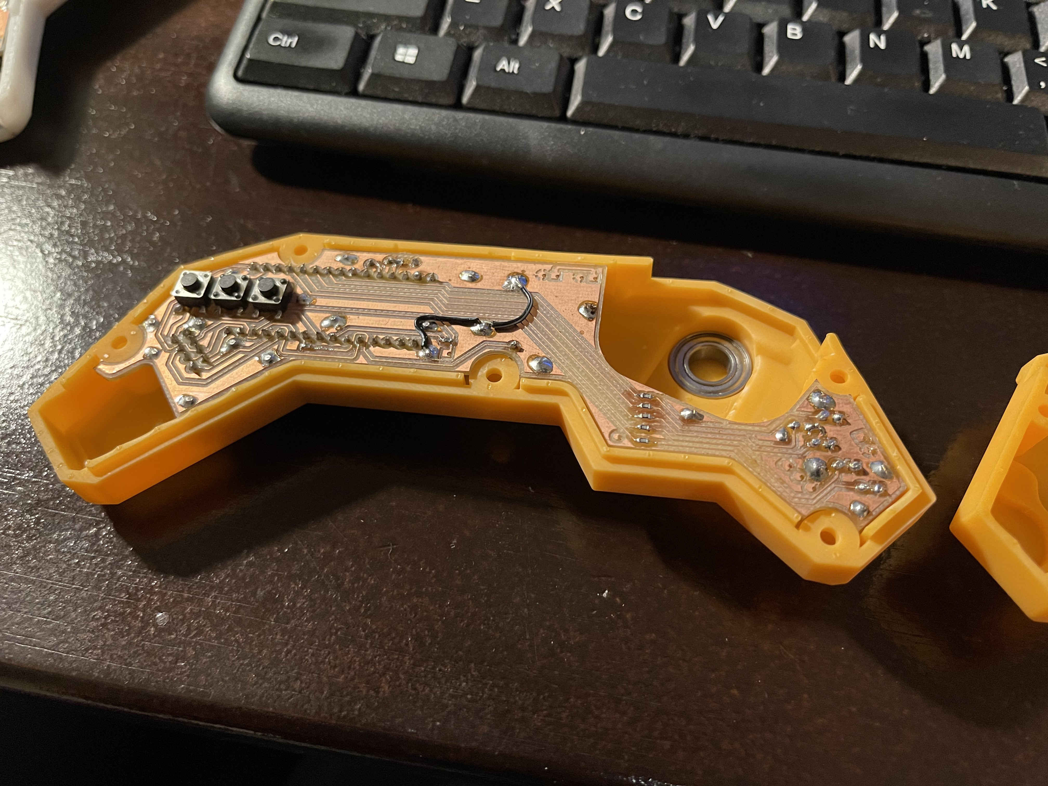
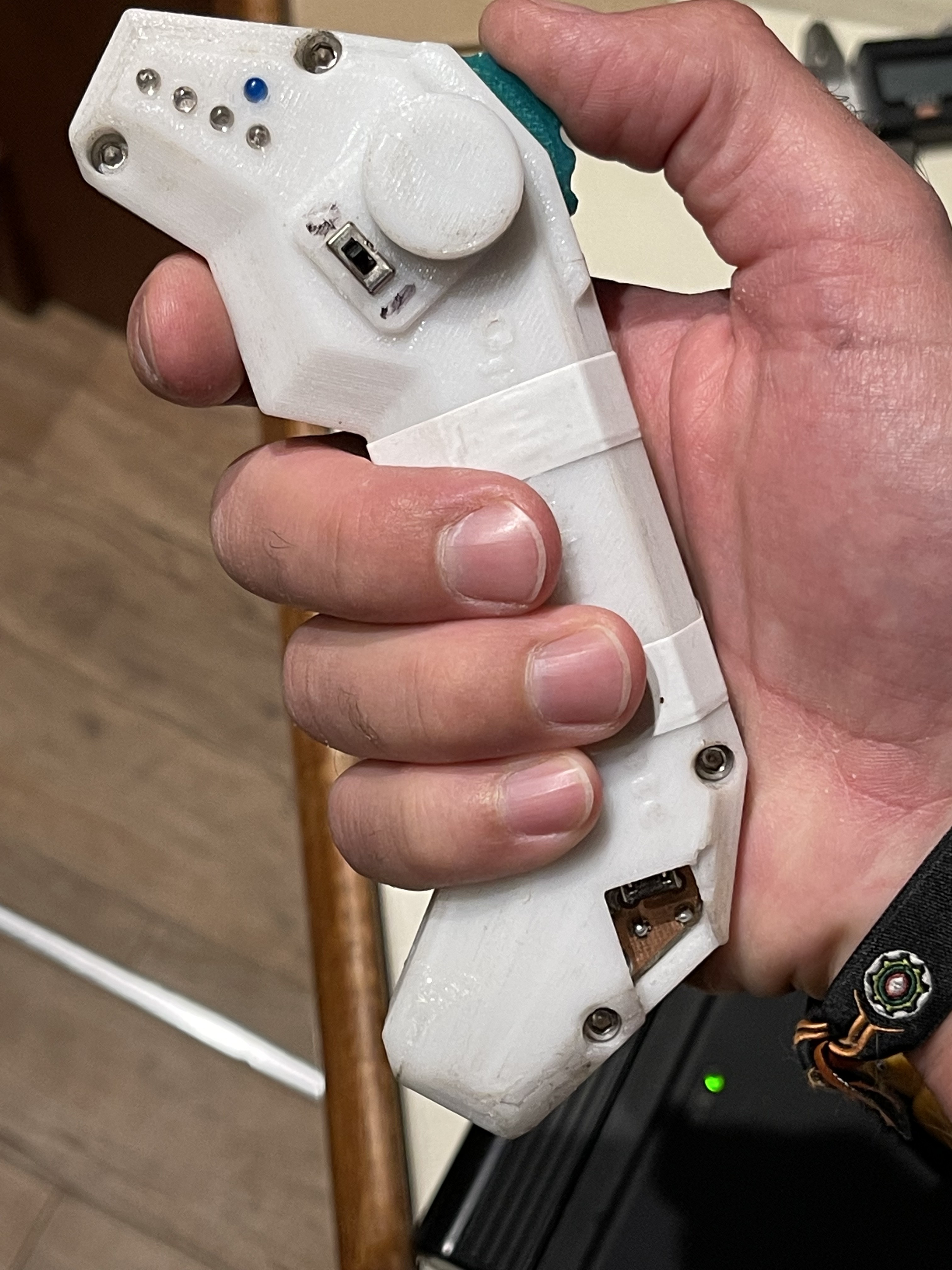
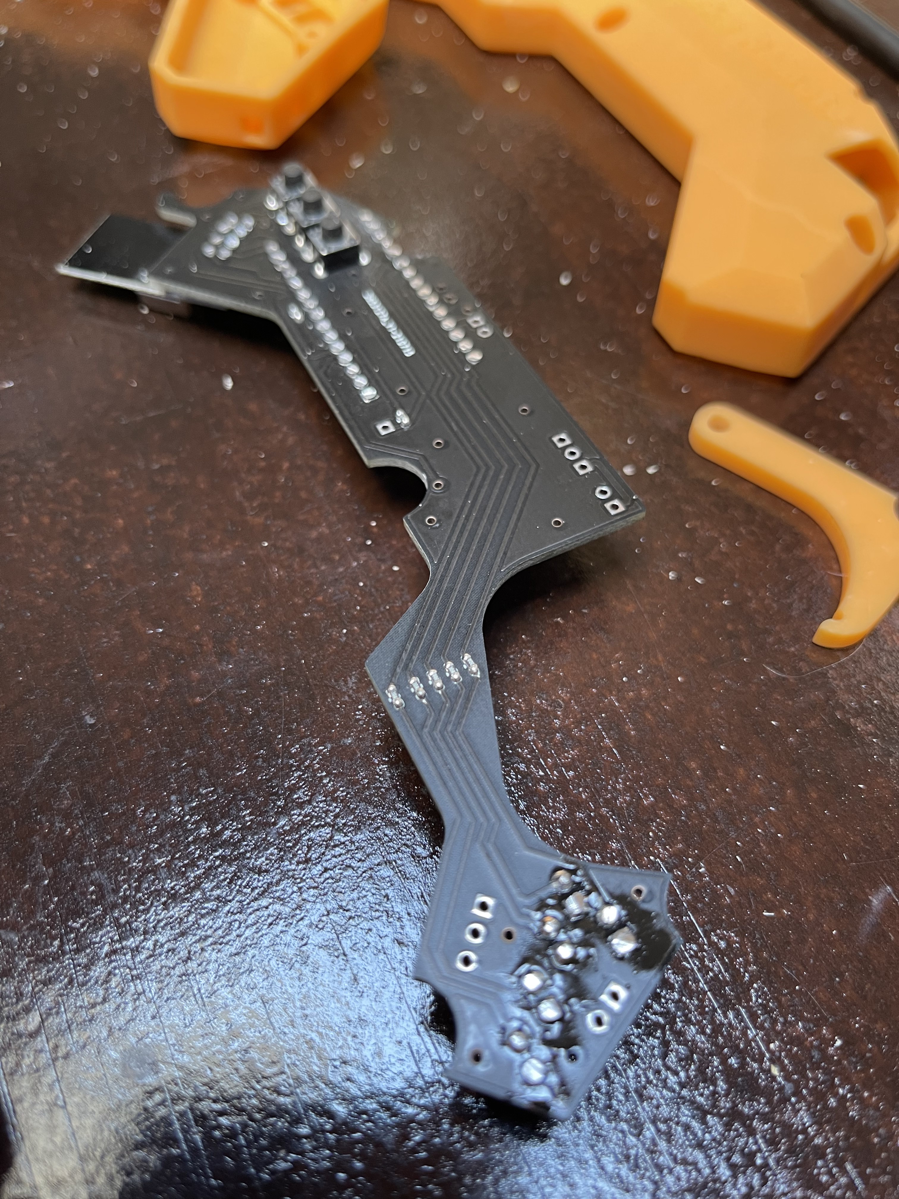
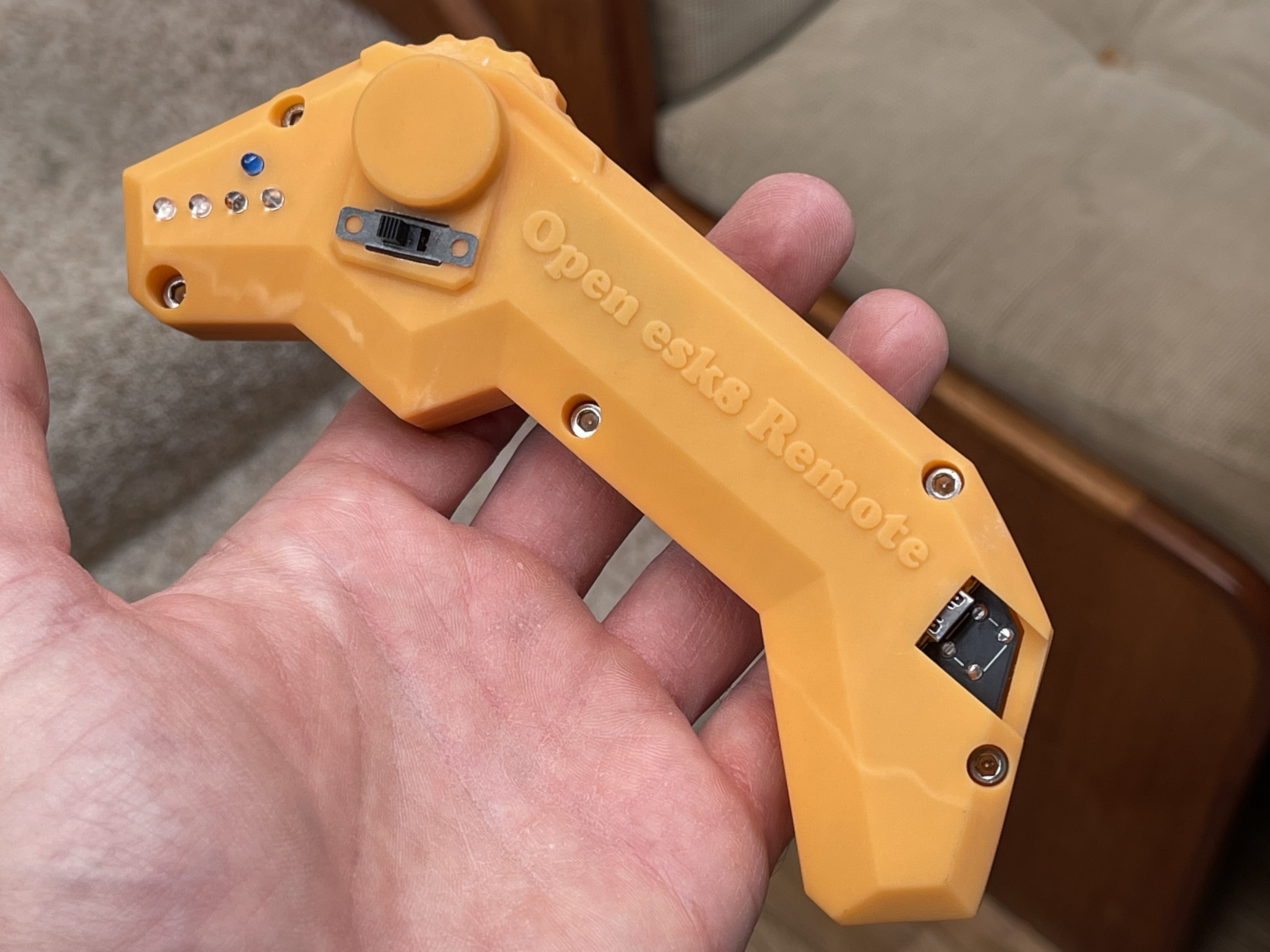
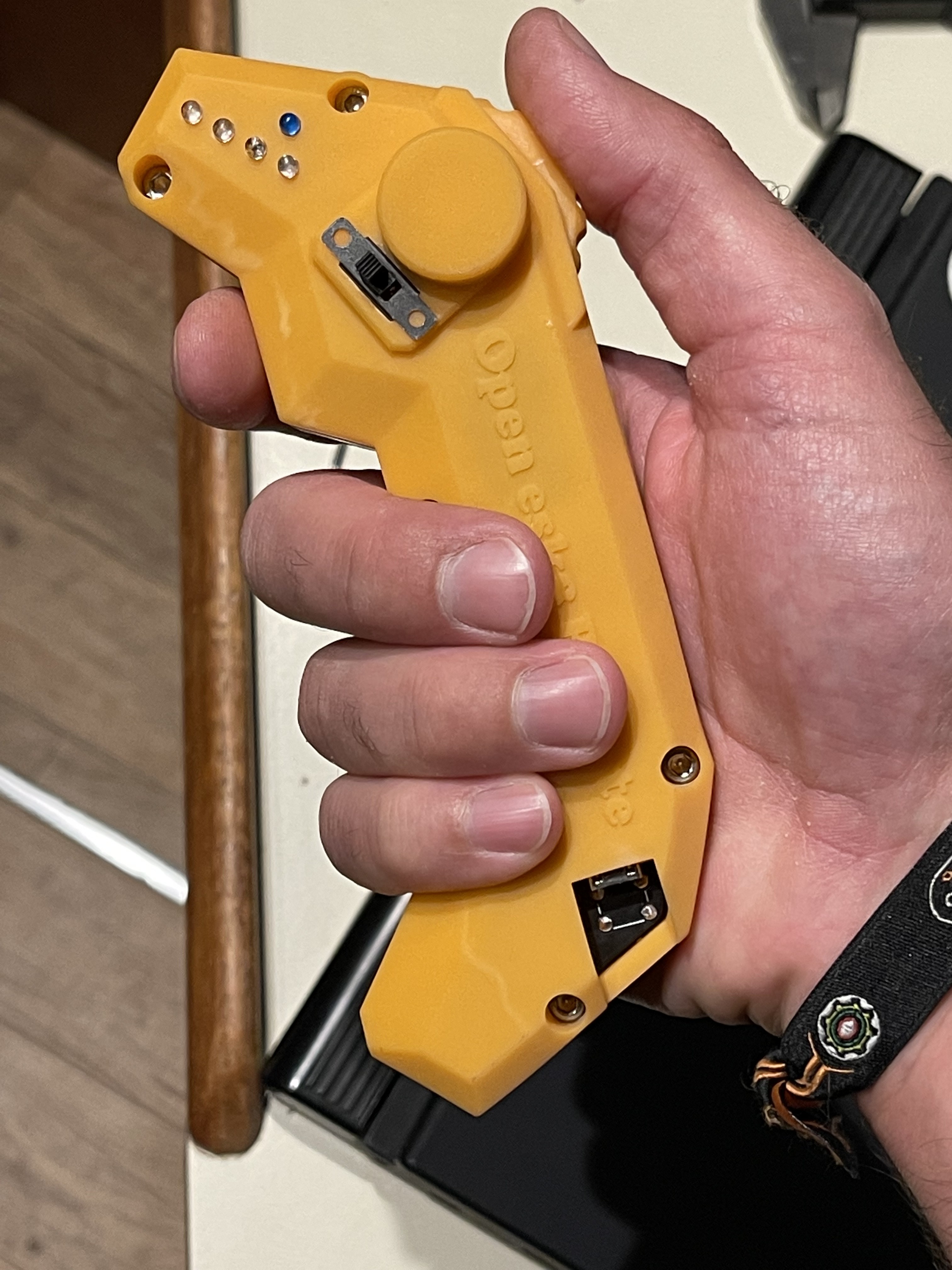
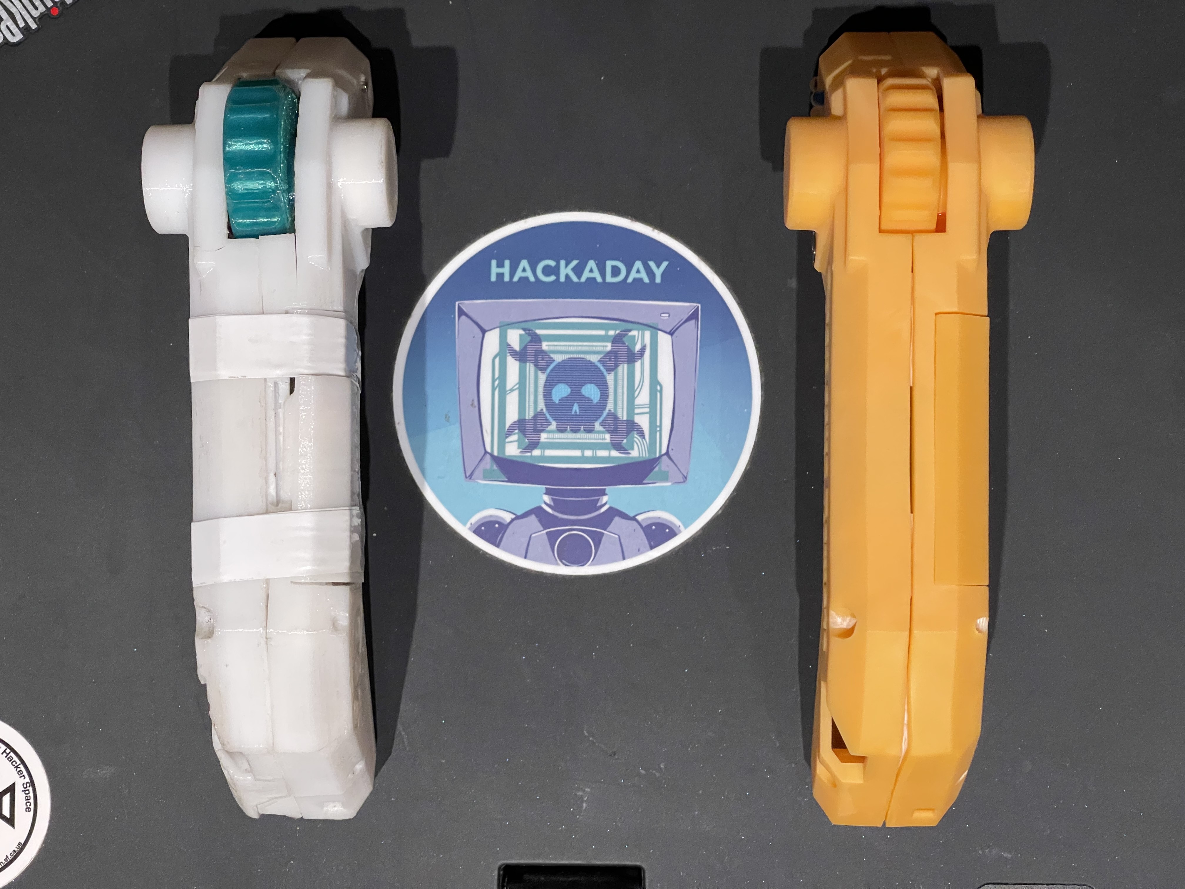
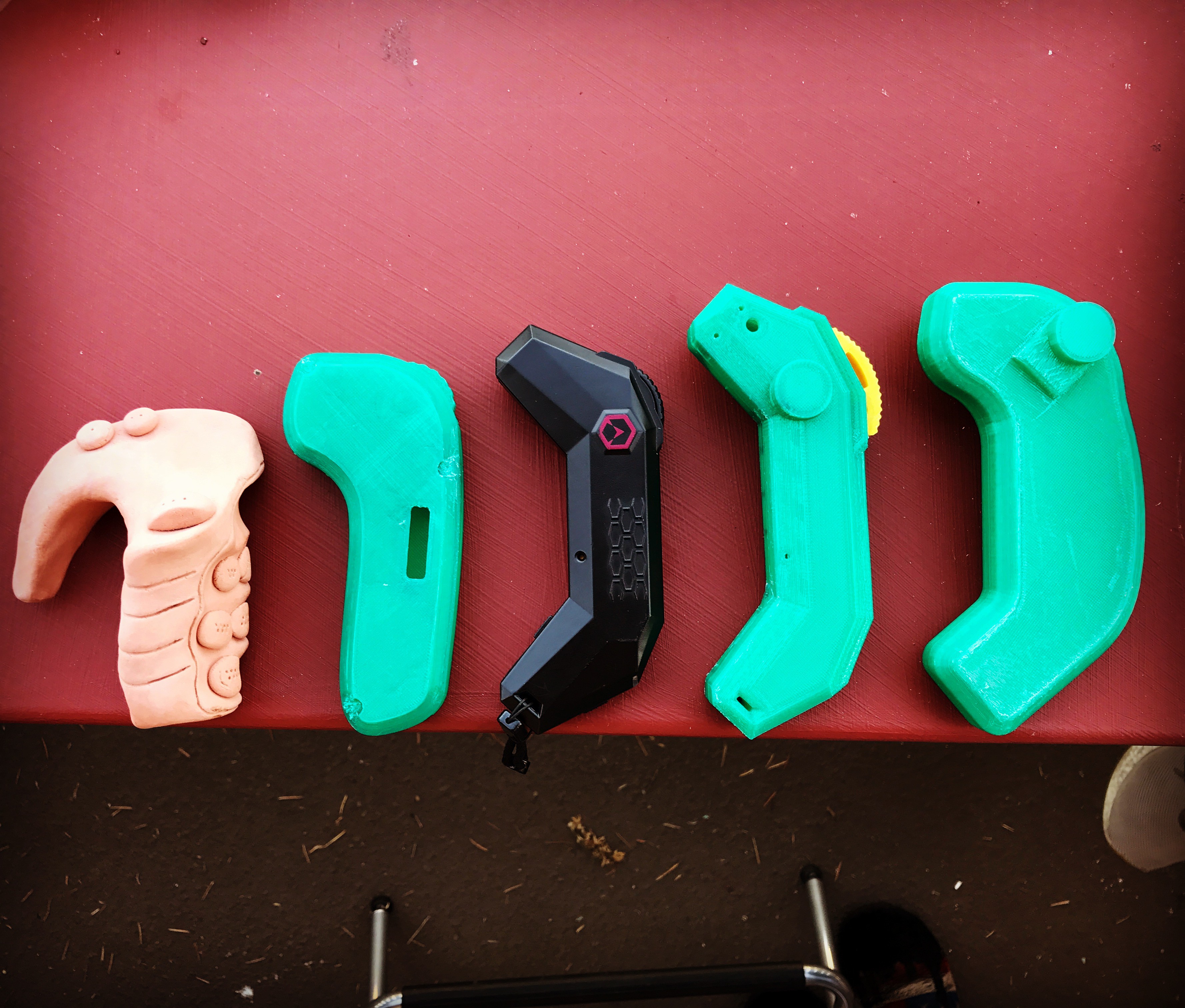
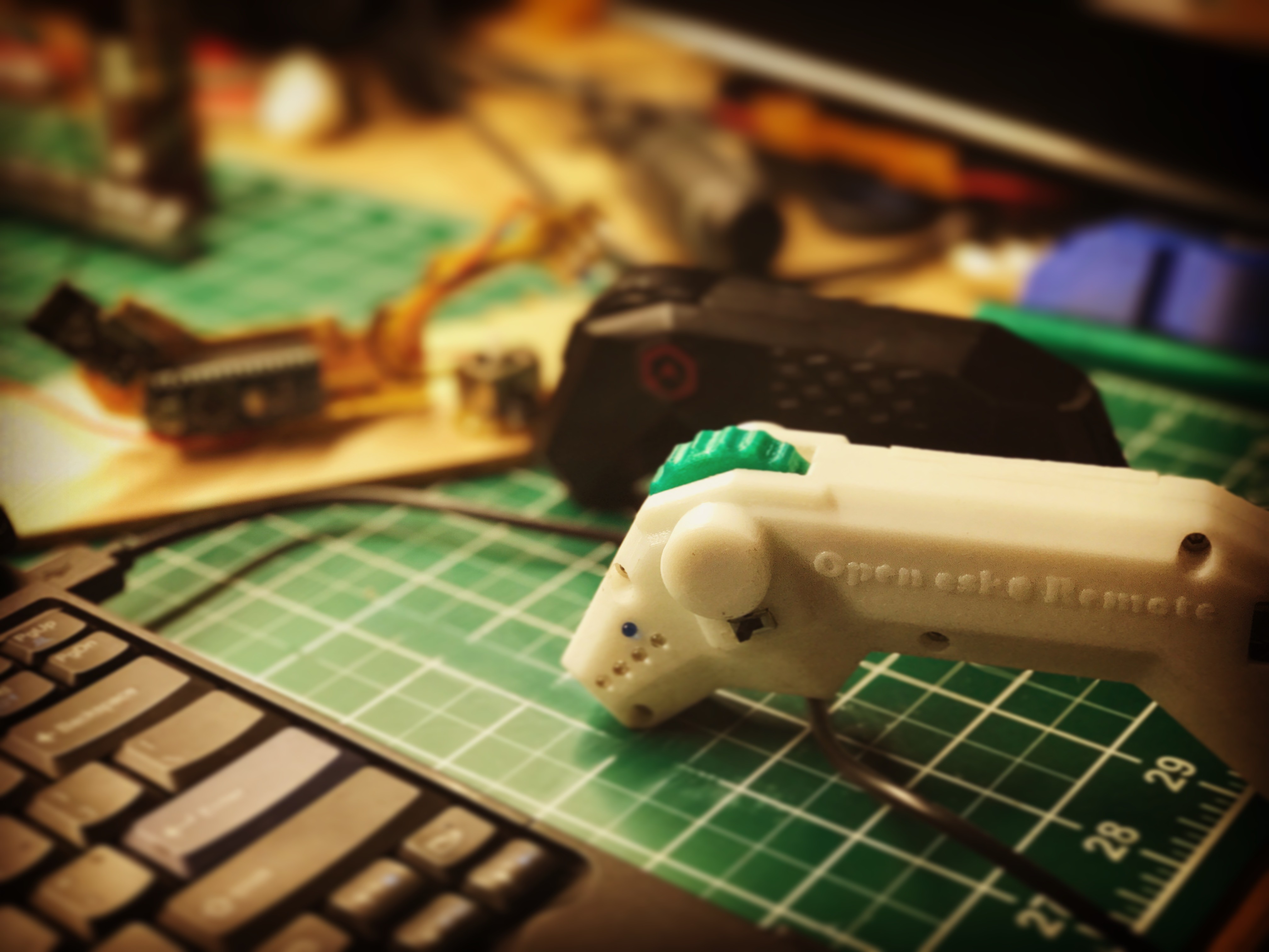
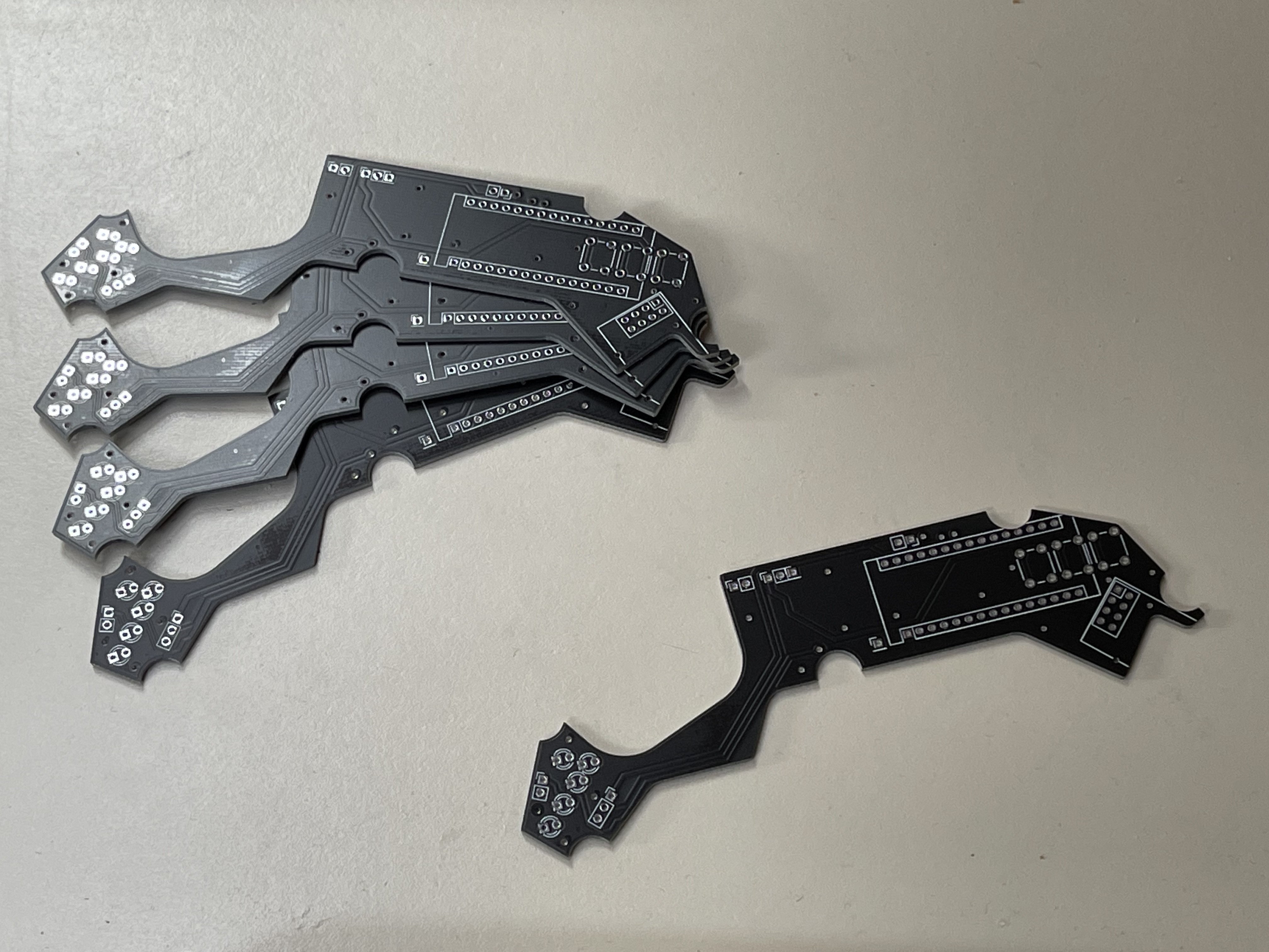
    Have you ever seen something this pretty in your life? Well okey, I show myself out....

    Regardless, after some sanding, the board fit and I was extremely happy with the result!
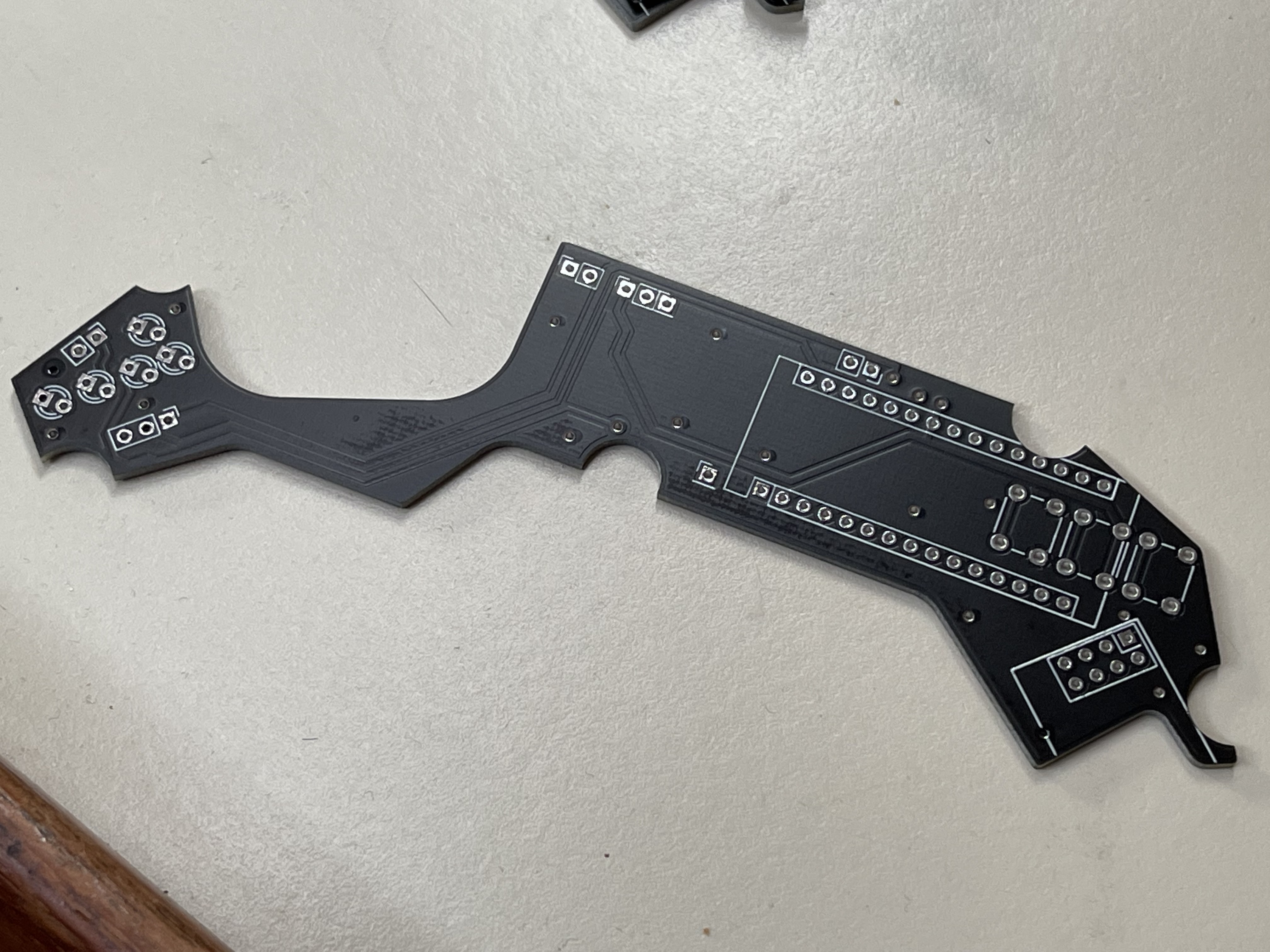
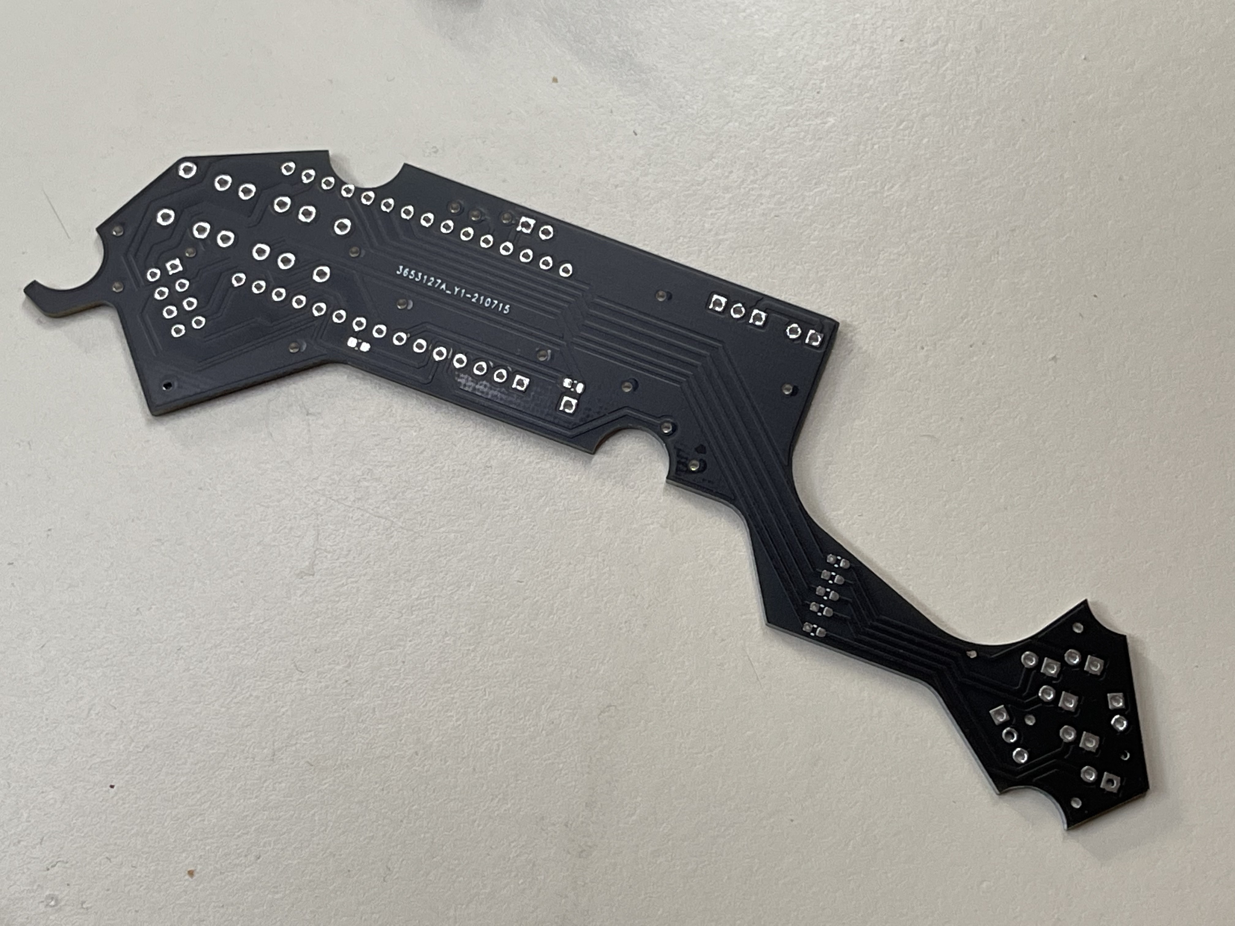
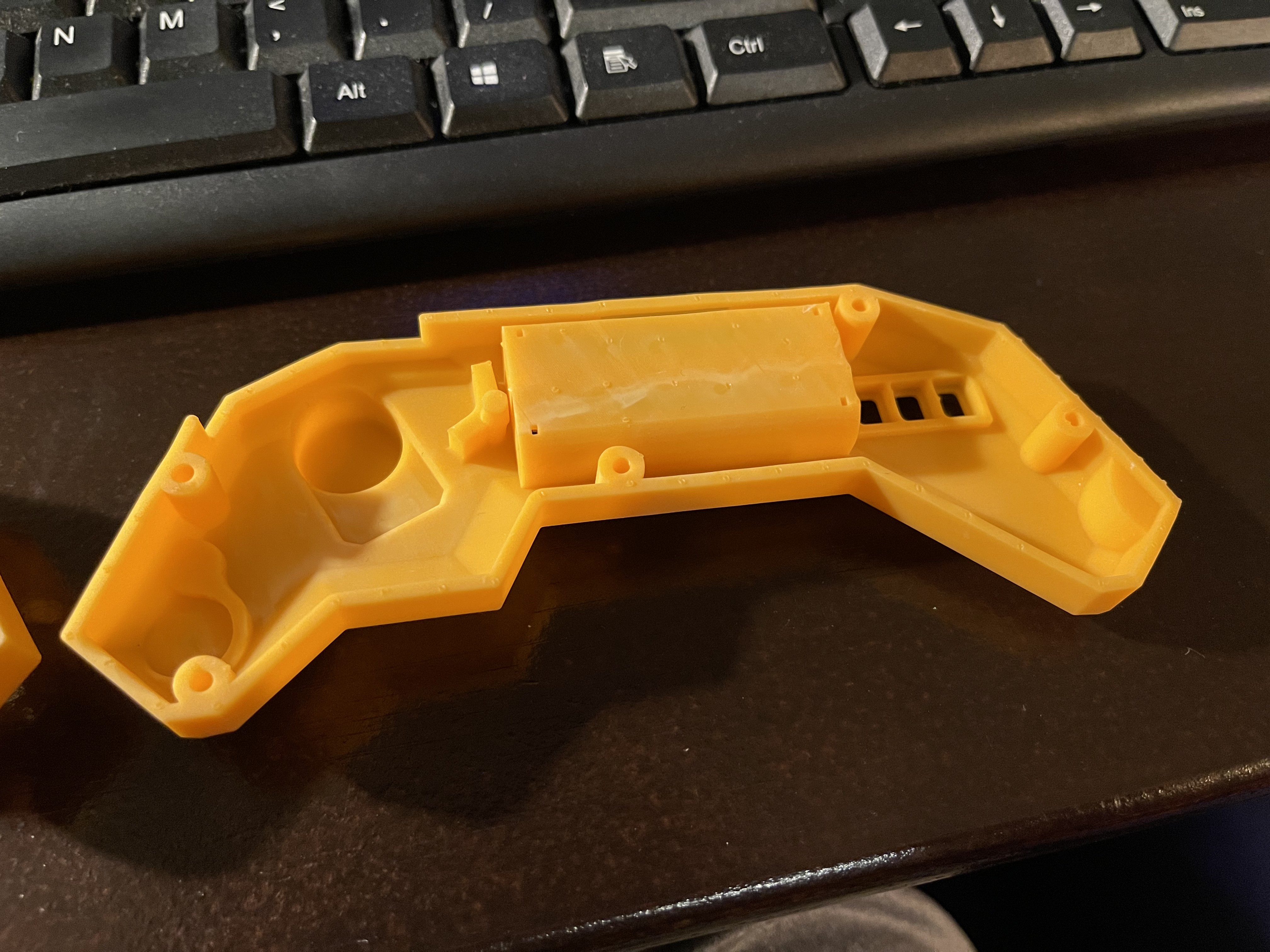
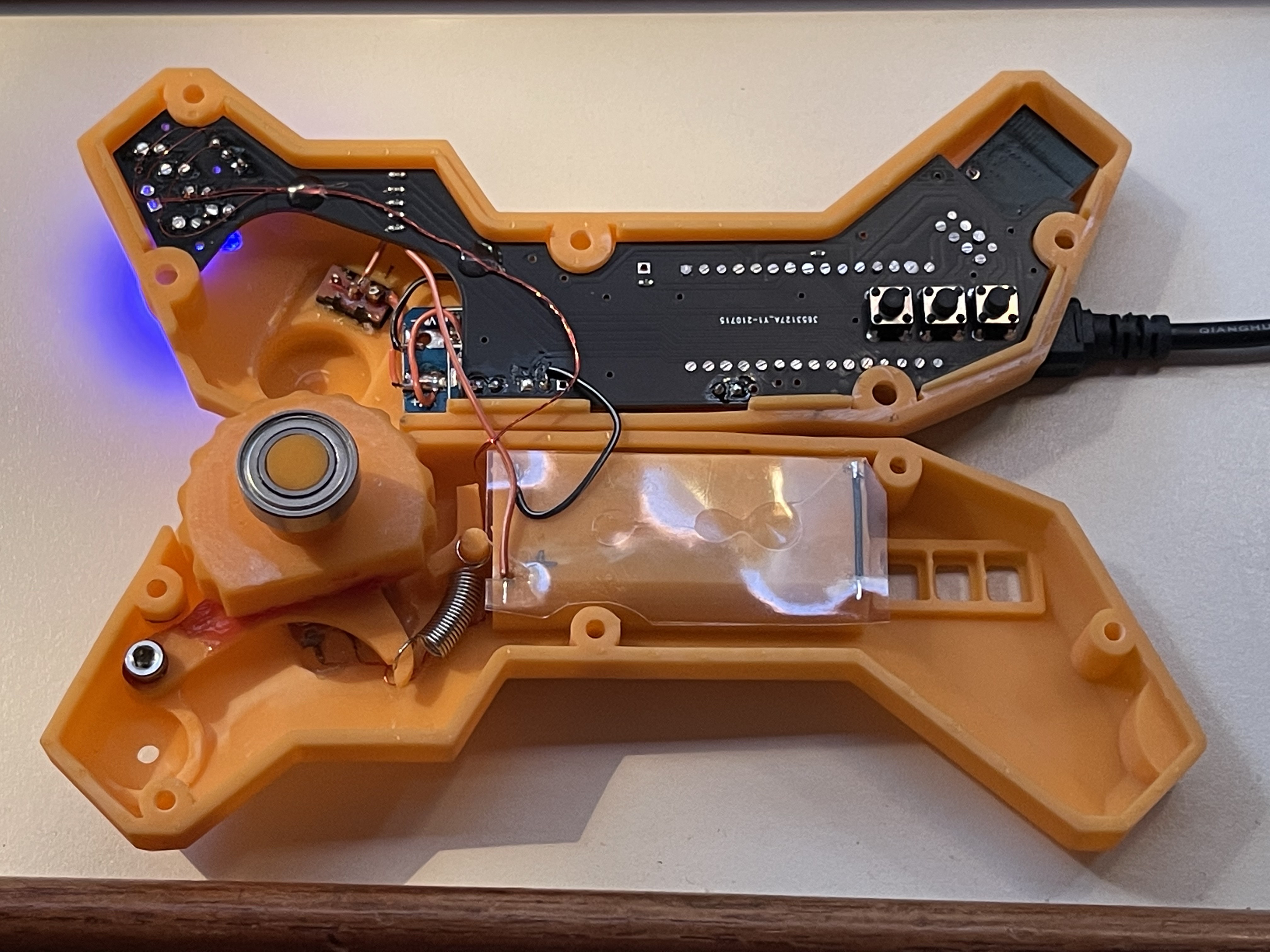
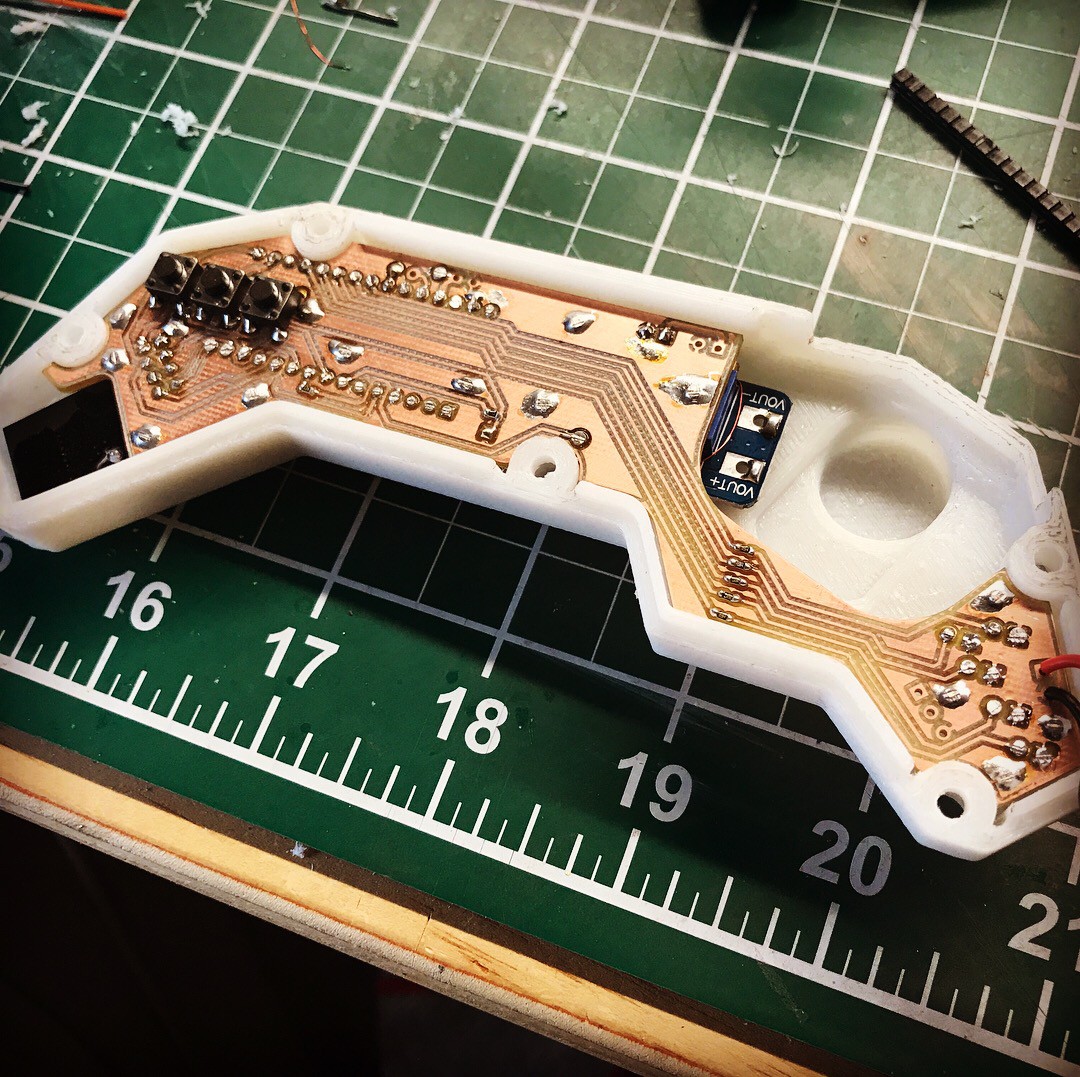
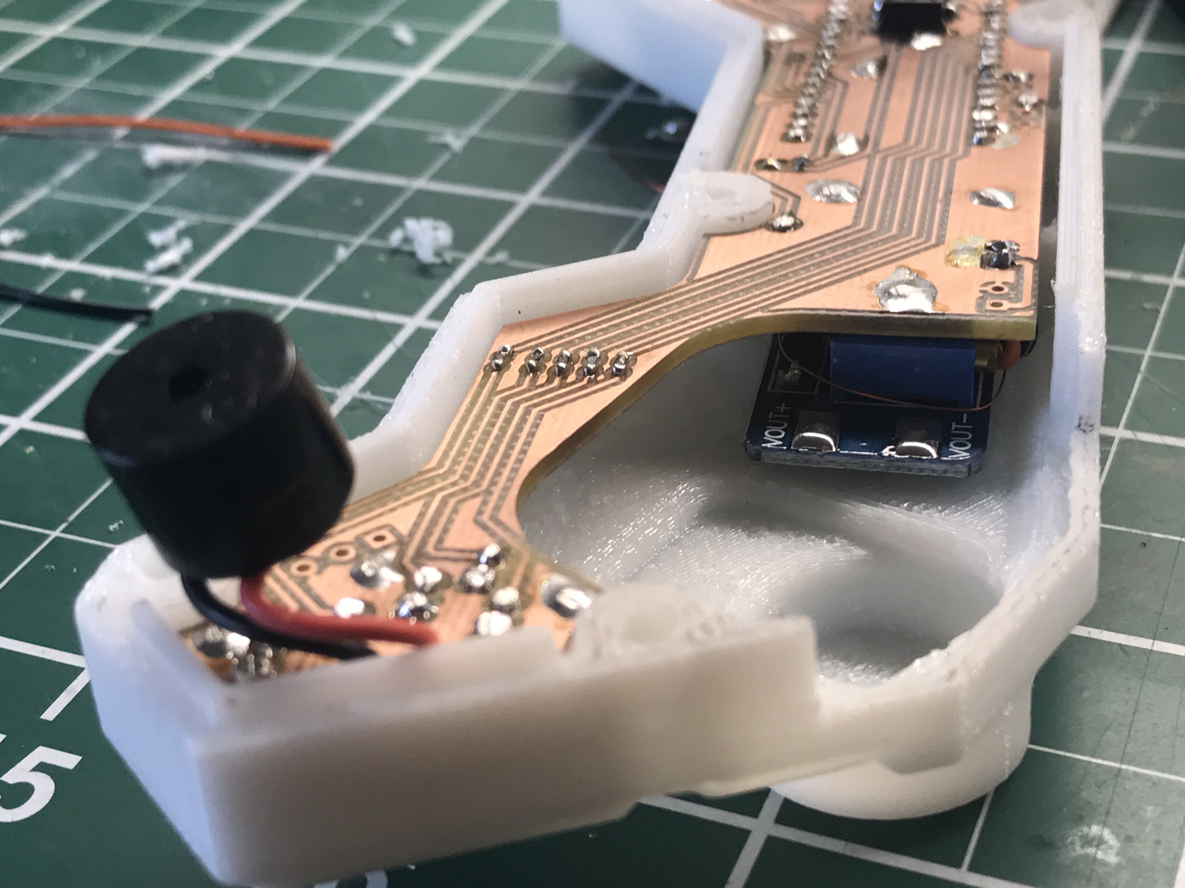
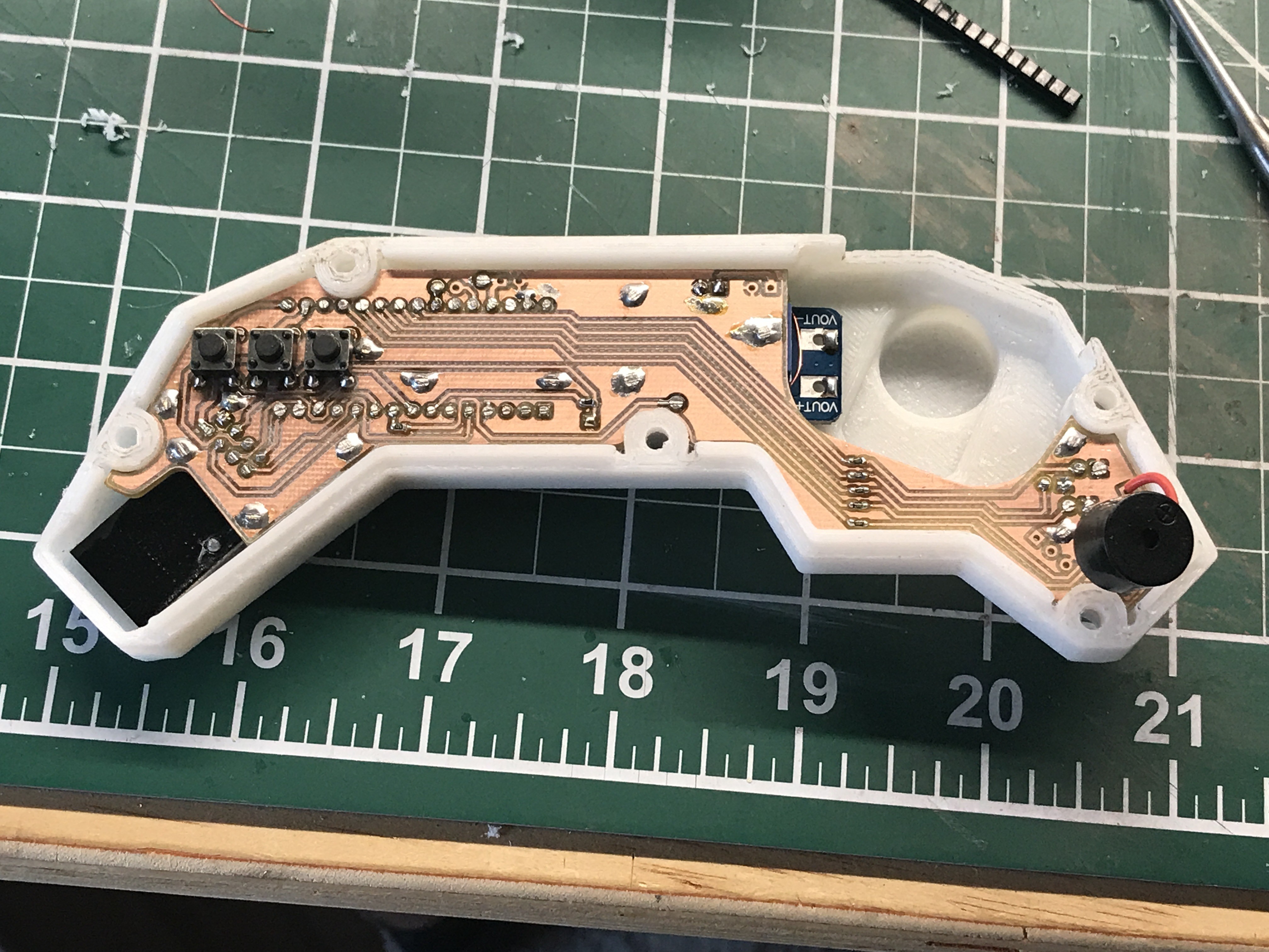
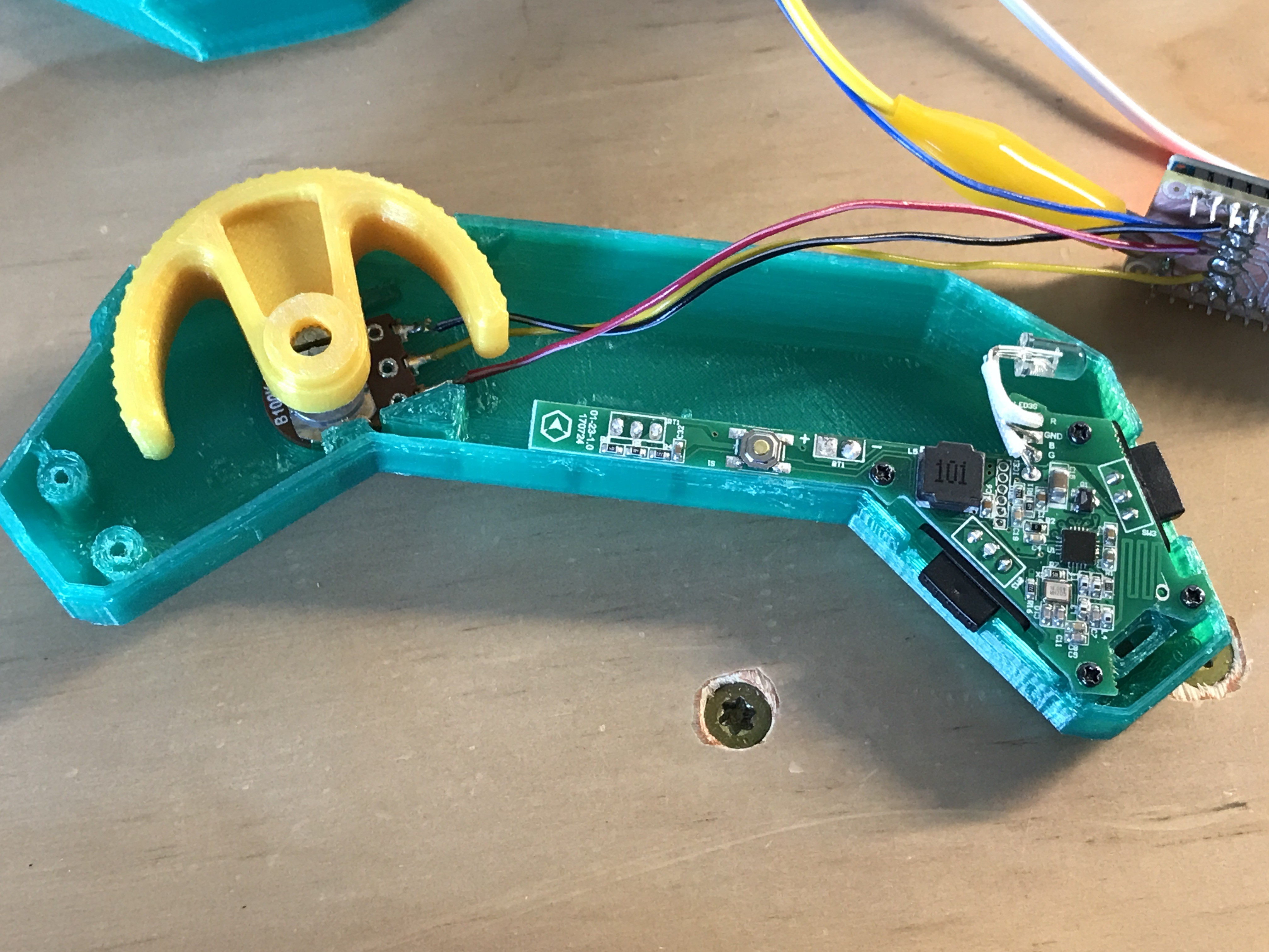
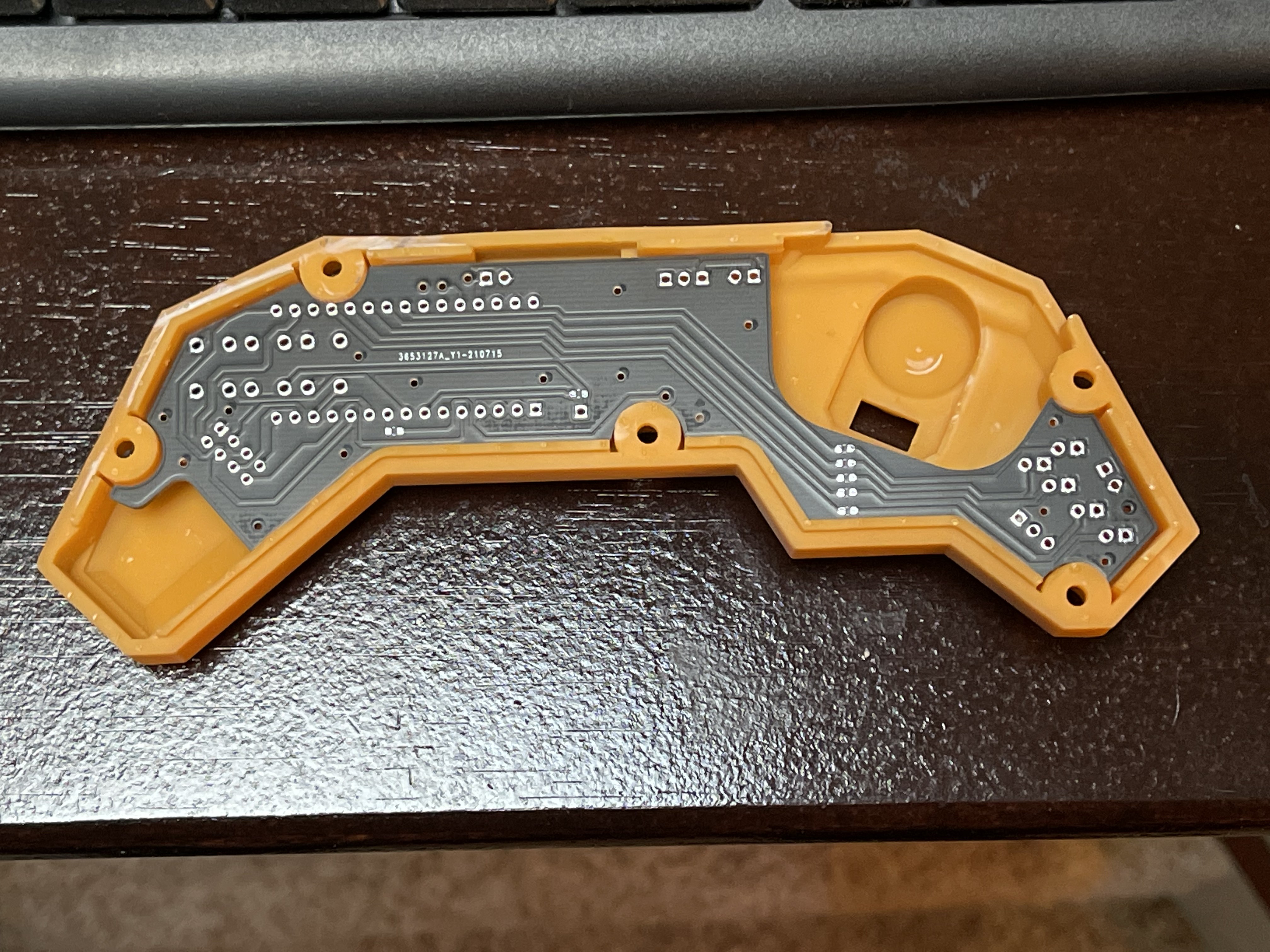
Some more sanding and the throttle potentiometer also fit into its seat.
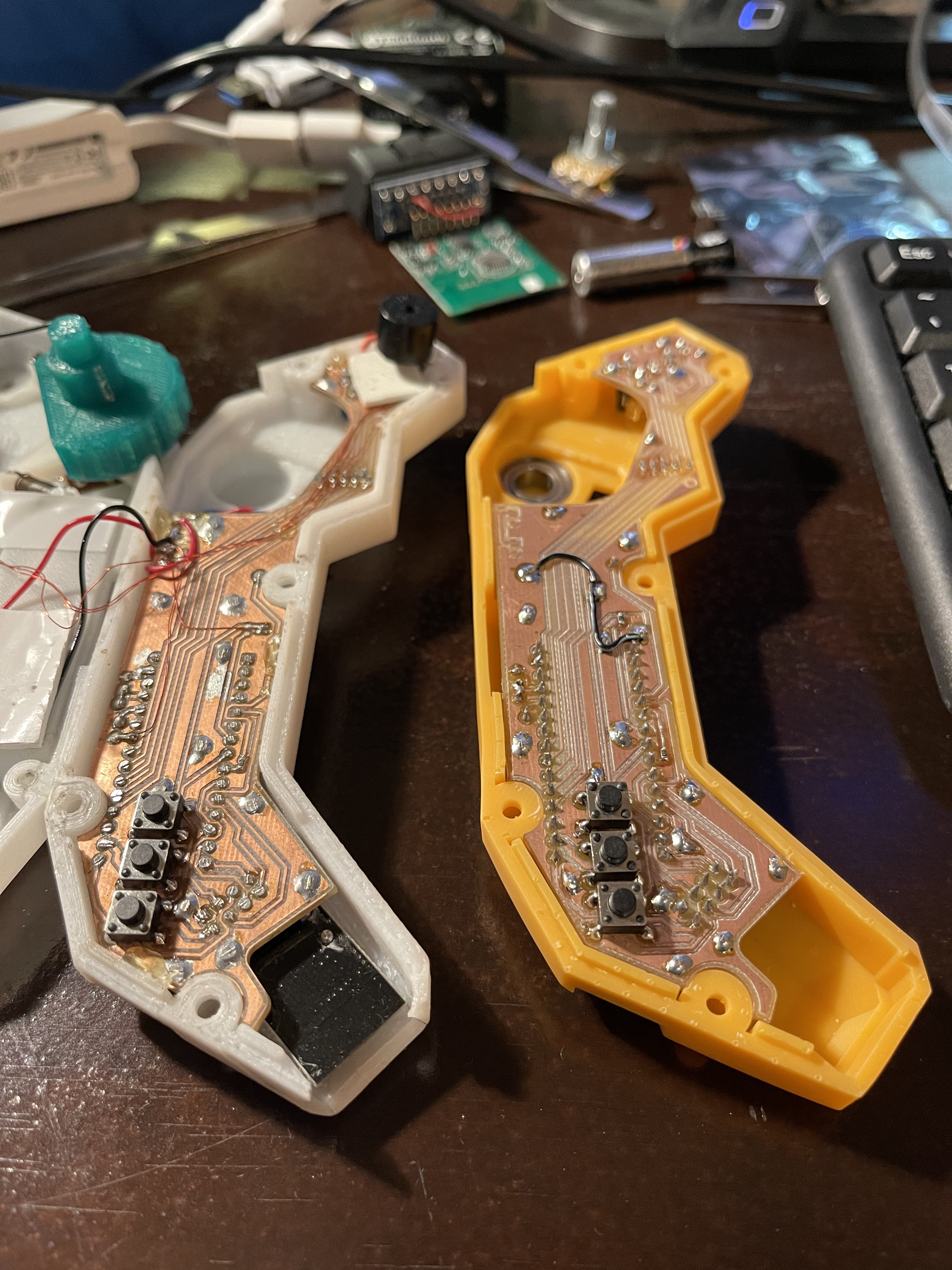
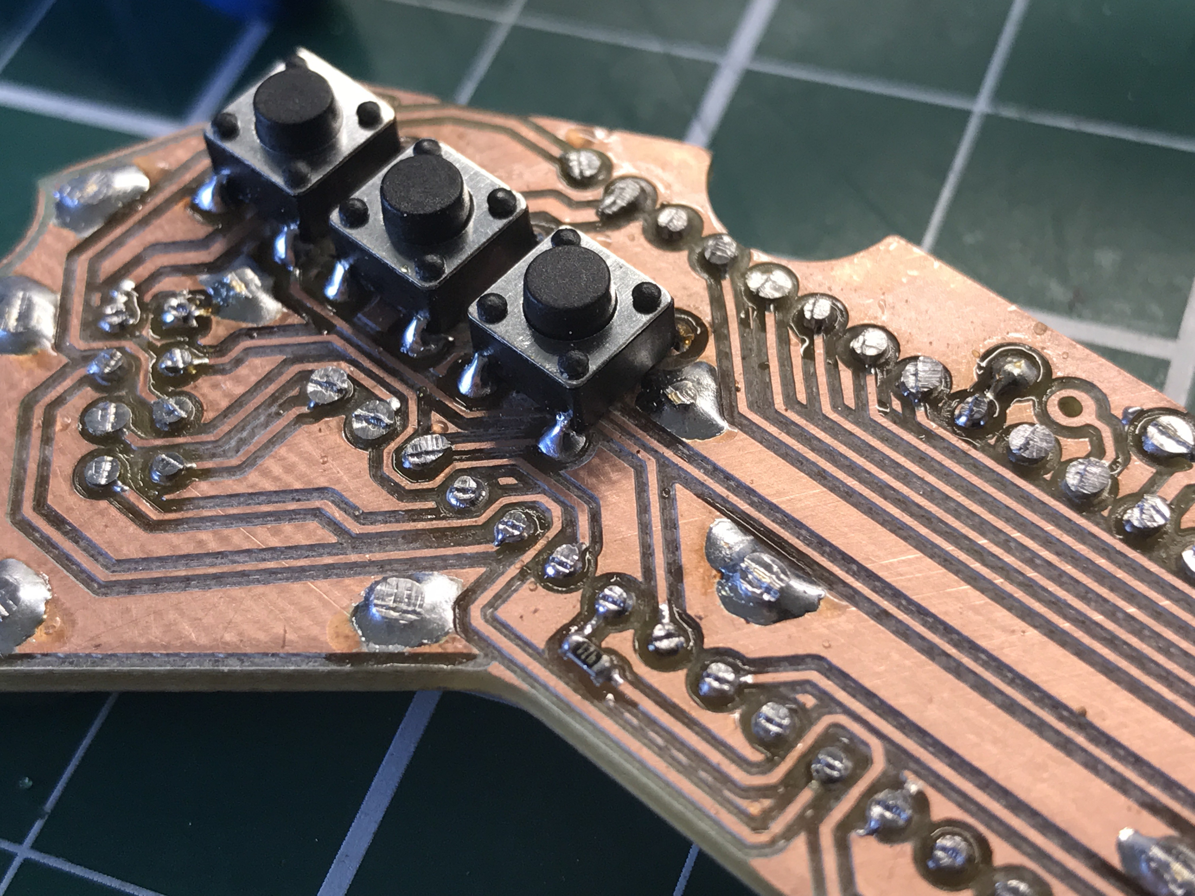
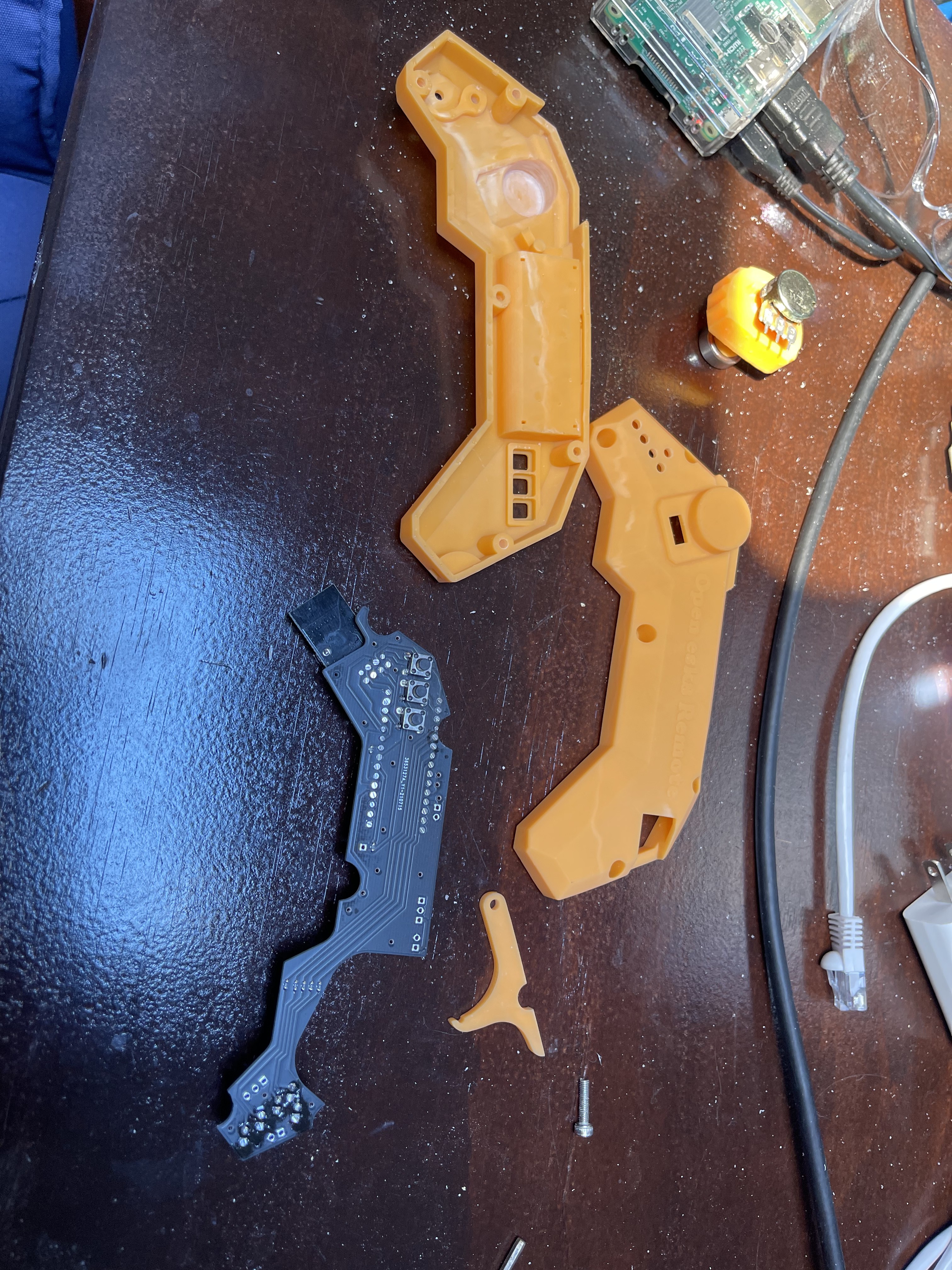
The board itself was quickly assembled now that I had the convenience of solder masks.
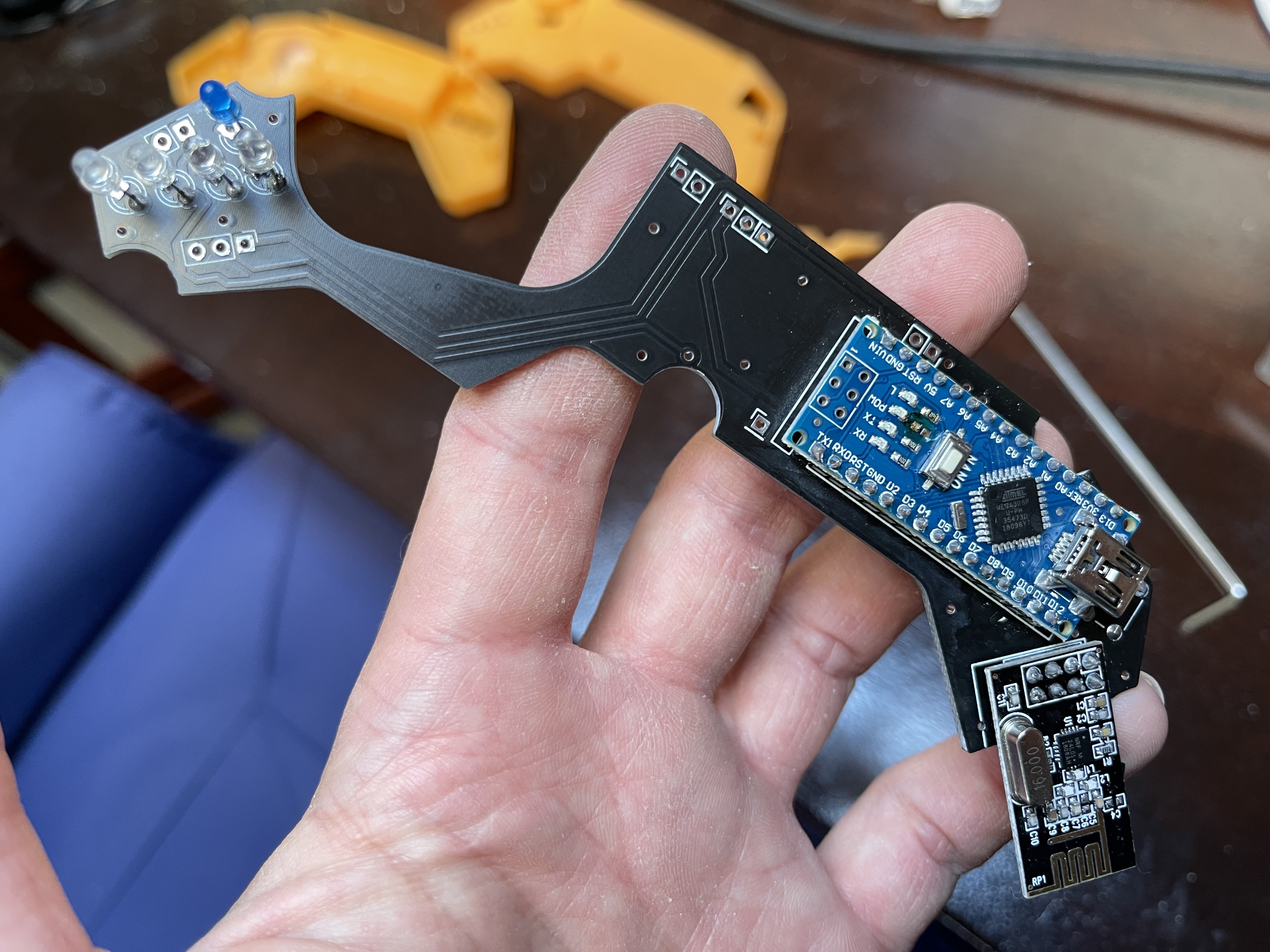
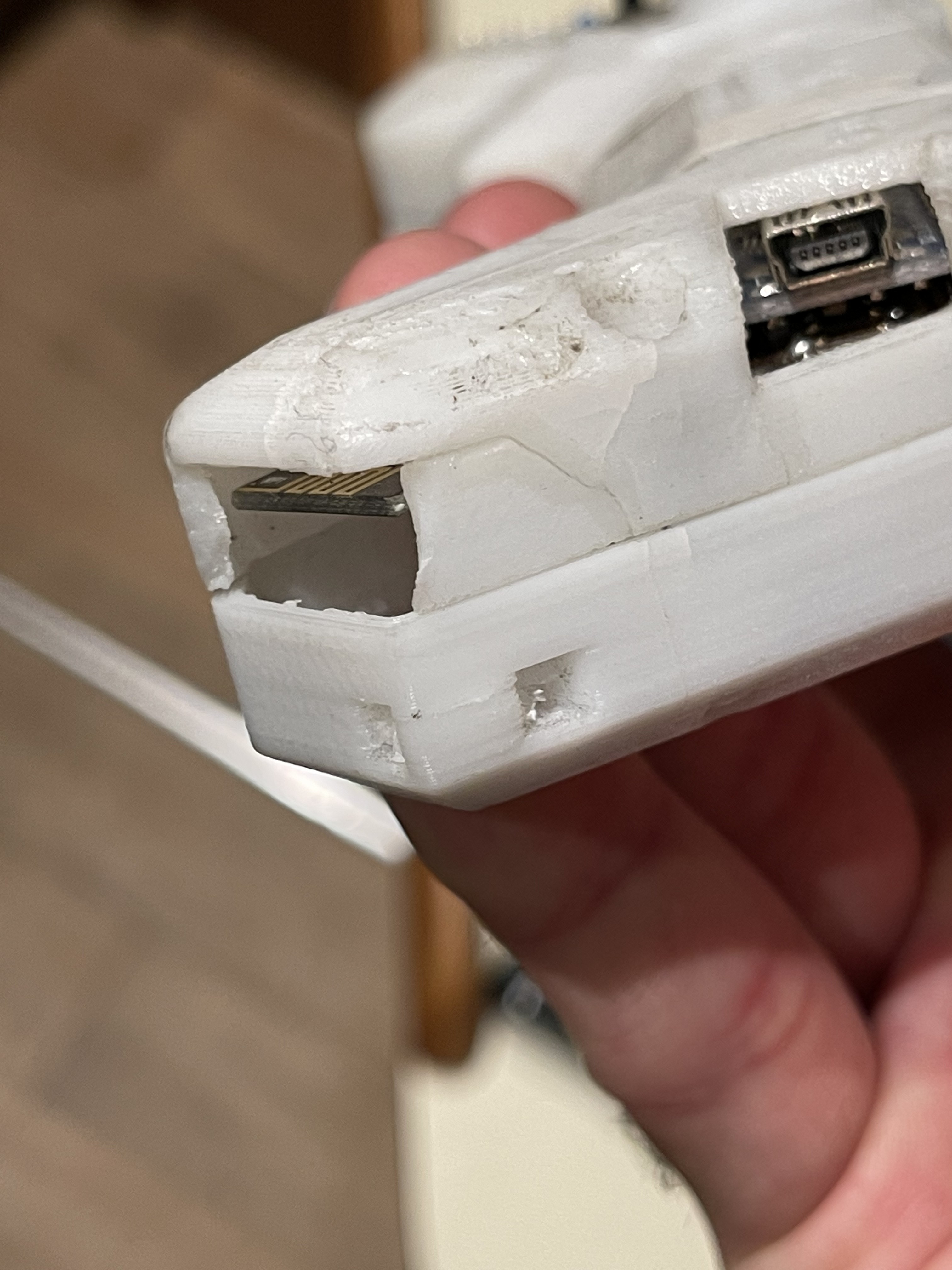
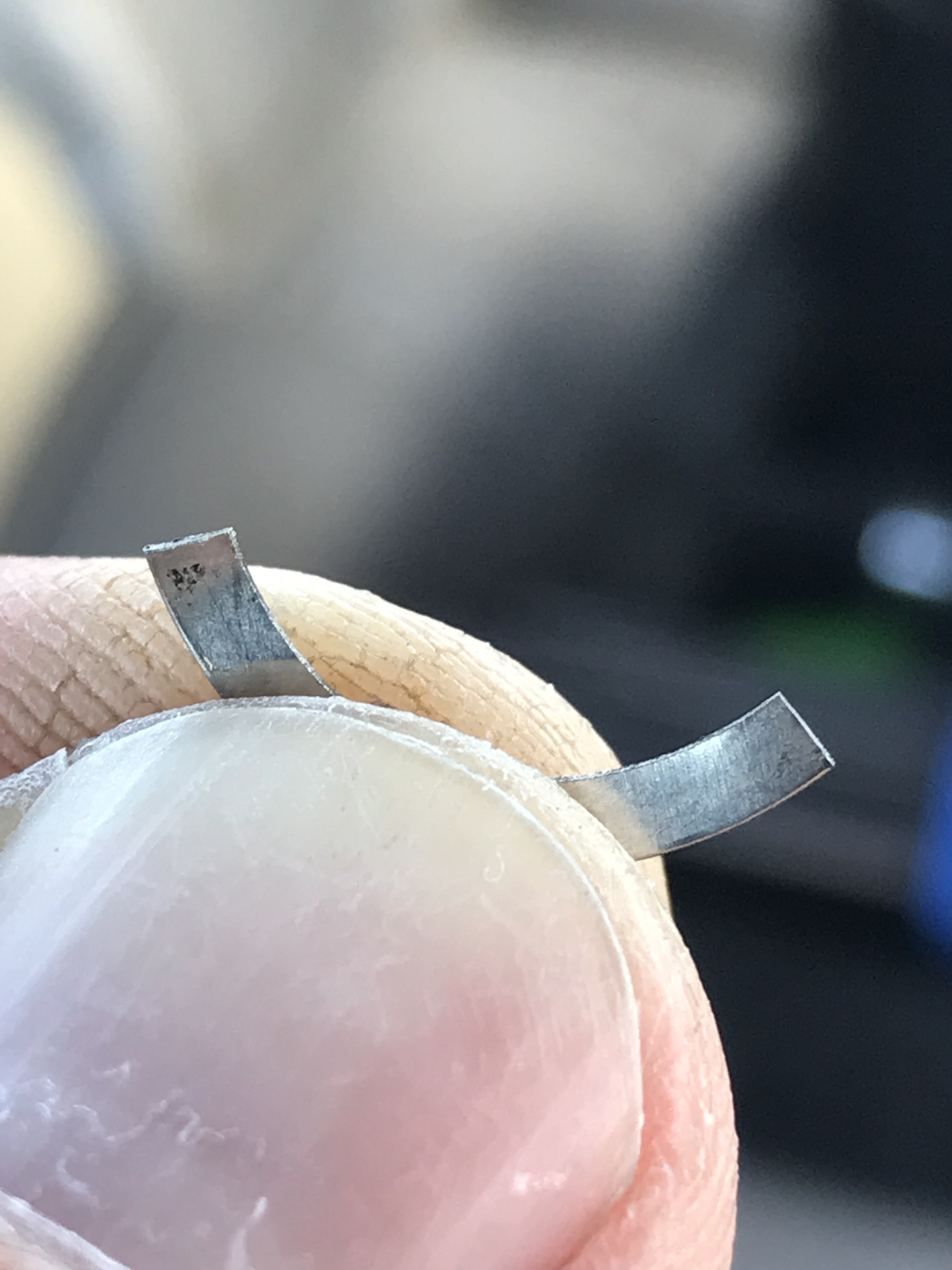
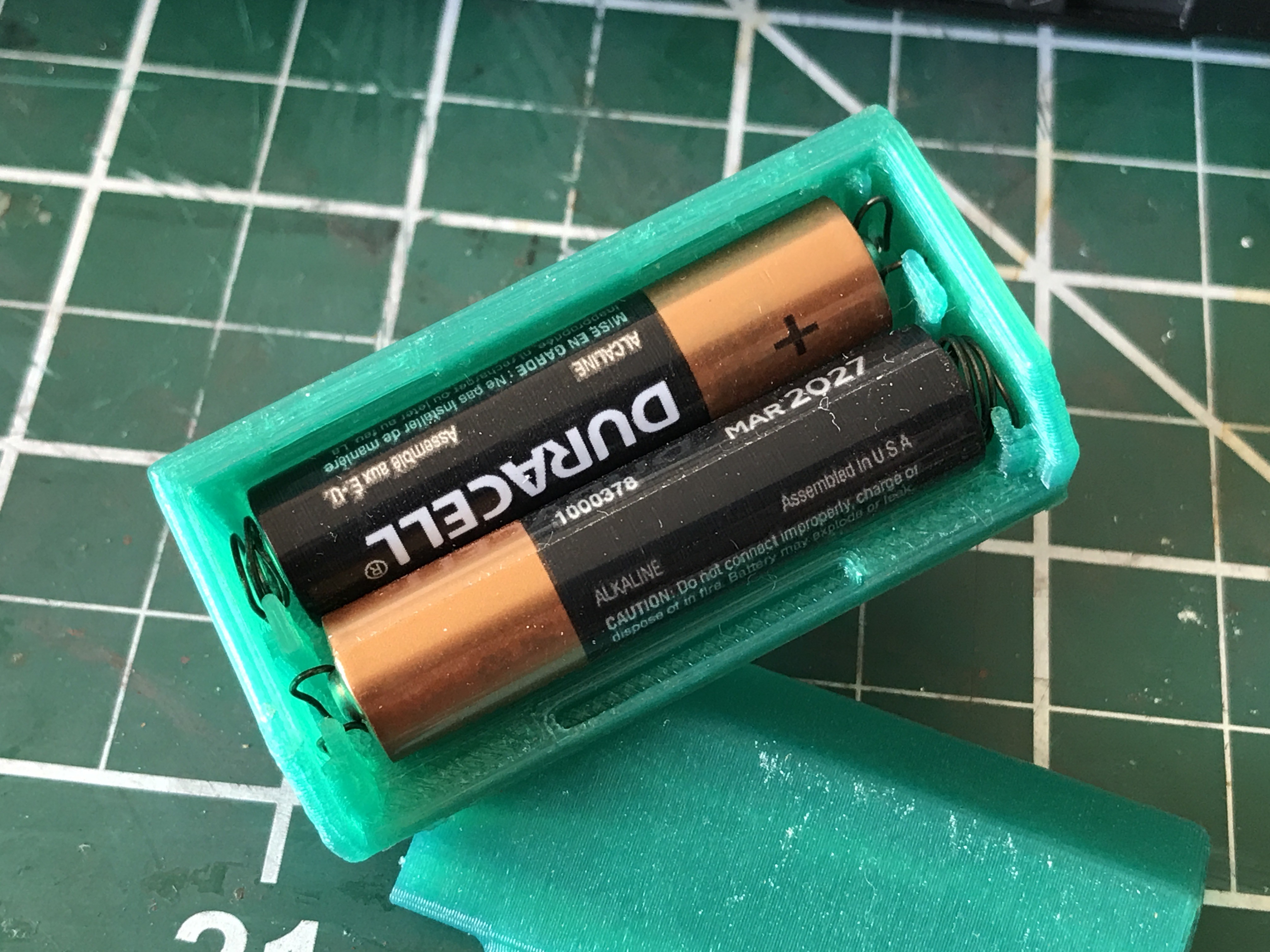
For the throttle return assembly, I bought some springs off of Amazon. A random kit of cheap springs. 

    Exactly what I was looking for for various reasons. One is that they are indeed cheap. But what makes them cheap is actually a feature for me: I can solder them and therefore I was able to use these springs also to make my battery compartment springs. 

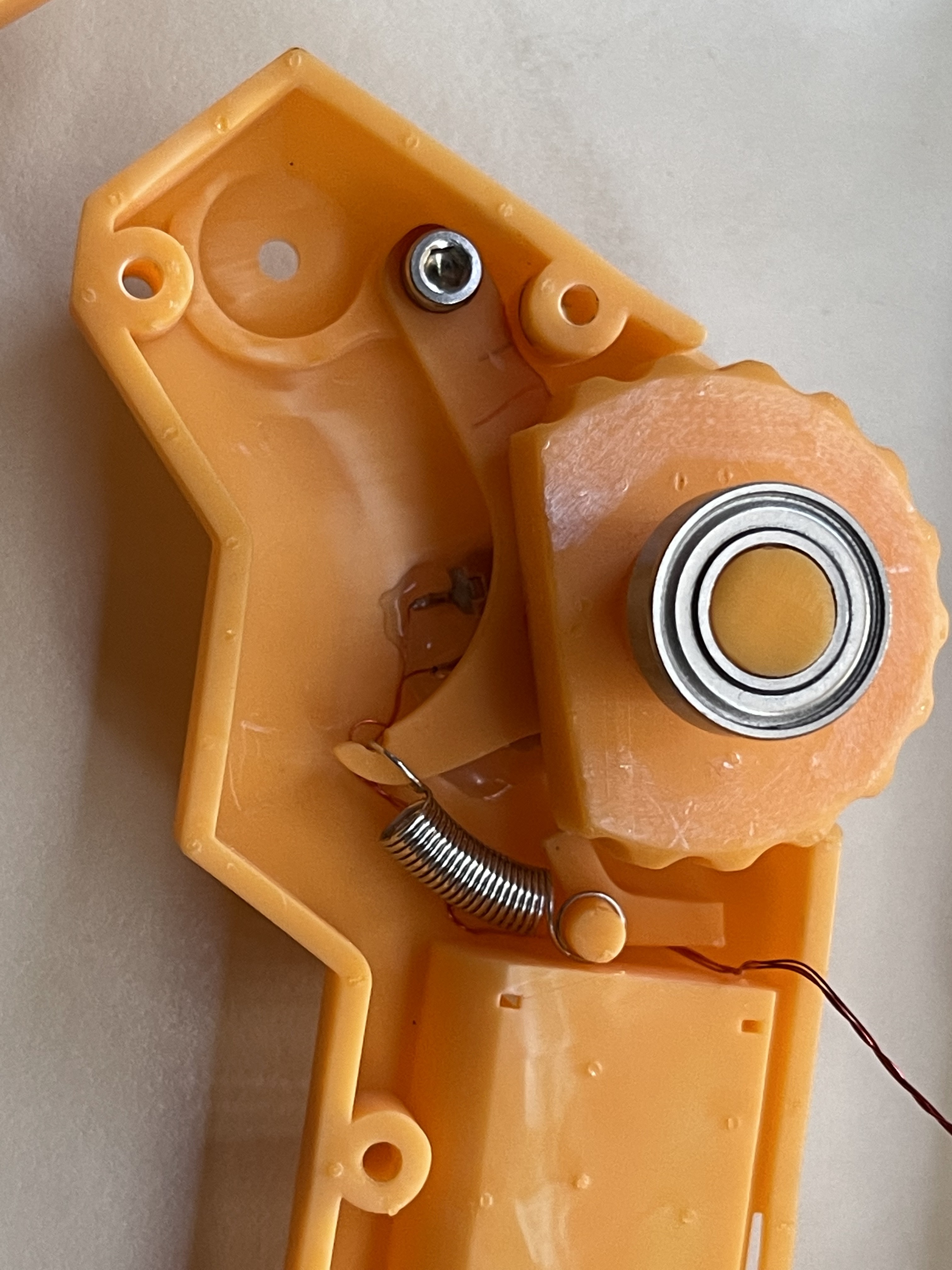
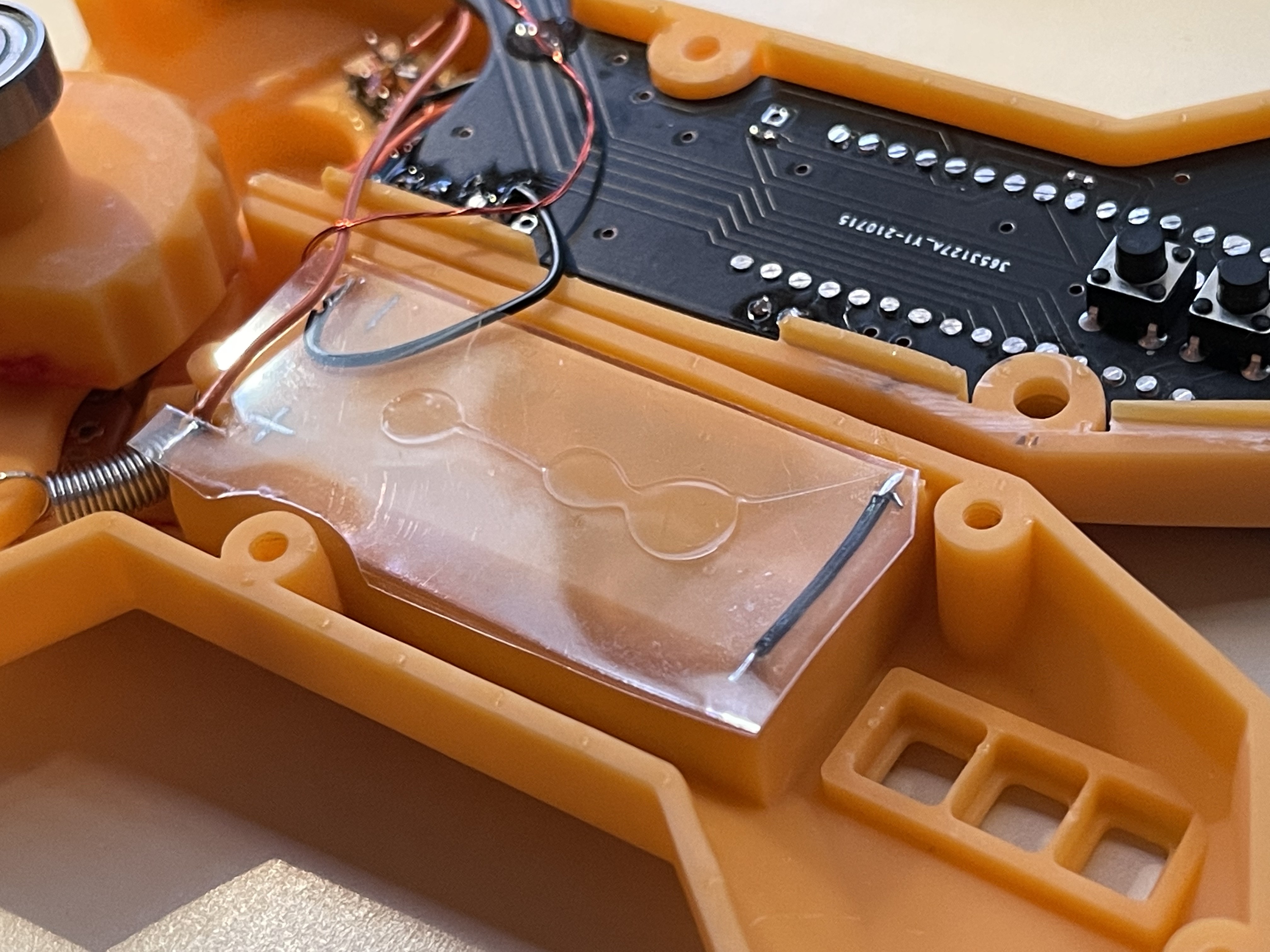
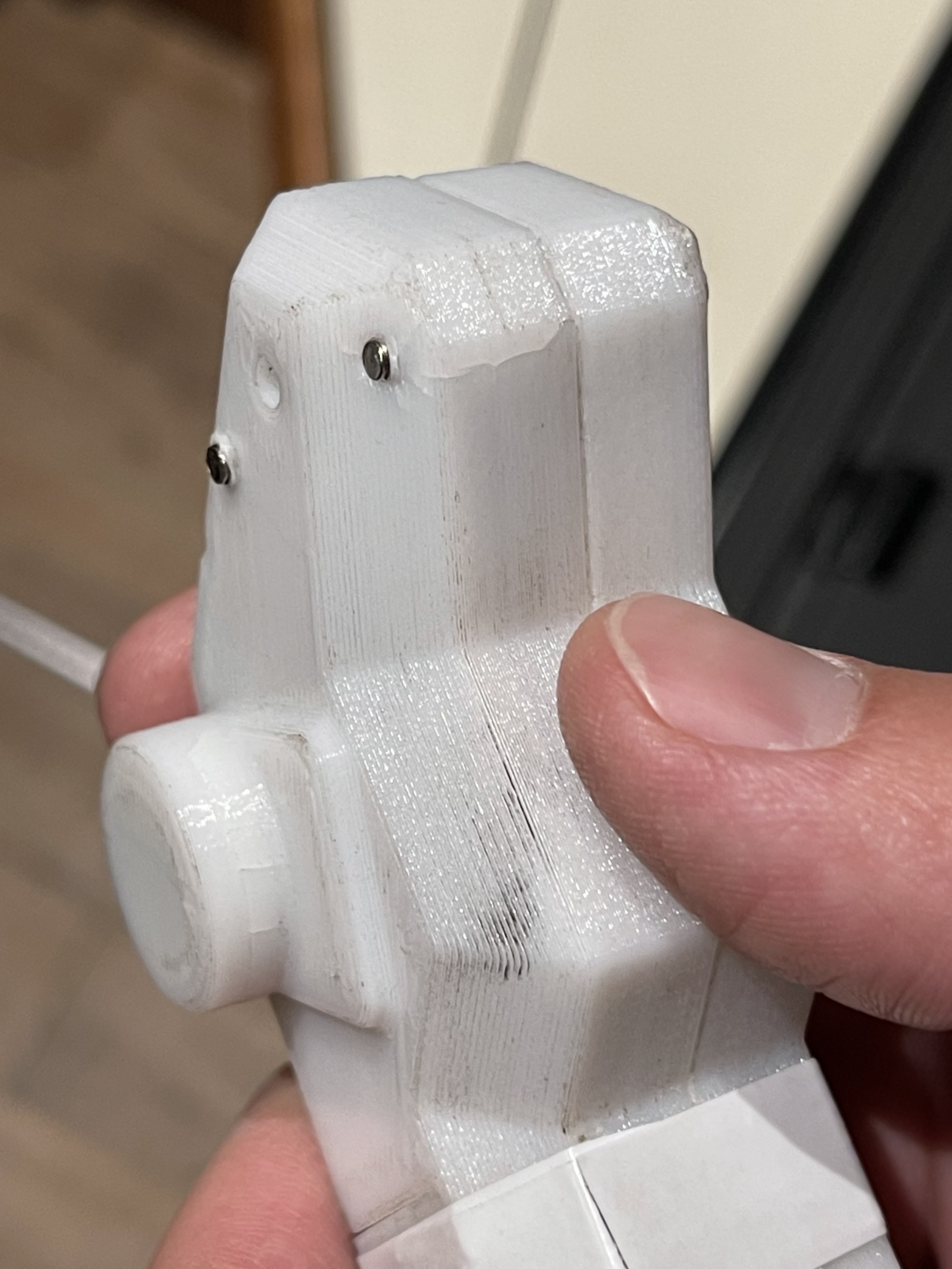
    In the end, with all the sanding and soldering, and destruction of an already glued in throttle potentiometer, it took quite an entire weekend to properly put this together. It certainly doesn't look like that in the pictures but it's the little things that take the most time. Even just getting the throttle to roll smoothly was an event....
    Read more »

  • Comfort Drive Modes - creating a smart remote

    Timo Birnschein08/01/2021 at 04:34 0 comments

    Since I started this project, I always wanted to implement multiple drive modes. I found it silly that Acton decided - or took the painful compromise enforced by cost and/or a lazy manufacturer of these motor controllers - to use the phone app to switch between drive modes. It's rather unusable and the drive modes don't even work really well. Why not just add a button to the remote that does that or implement the drive modes within the remote in the first place. The latter was the only option for me as I have no control over the bluetooth connection (yet) and didn't want to mess with the board electronics more than absolutely necessary.

    I wanted three modes:

    • Beginner: A mode that allows even the most inexperienced drivers to take this super powerful board for a spin. This mode needed to be extra smooth in acceleration, coasting, and braking. It also needed to soften how the board behaves when one just lets go of the throttle or the brakes.
    • Cruise: A mode that is equivalent to the beginner mode of Backfire boards. Something that drives about 13 mph and is very gentle in terms of acceleration and smooth in terms of braking. However, it should allow full brakes to be applied because when cruising we might be moving through city traffic as well.
    • Performance: Full power and direct control with minimal latency between throttle/brakes and board reaction.

    Up to this point I had a pin assignment bug in the firmware that would not allow me to use the mode button. That was an easy fix via reassignment. Now that I had a working mode button, I first added a state machine to switch between the modes and then implemented throttle limits and throttle filtering via a simple differential control loop with adjustable gain to smoothen how the board reacts with respect to the throttle input.

    After I finished the implementation and preliminary testing with the wheels up in the air, I went out and tested the new drive modes. I love heading out with my crusty laptop in the backpack, stopping, tuning, driving, stopping, tuning, and so on. That’s how I like spending my day :)

    Adding a Vehicle Model

    However, it wasn’t done with just tuning. The issue I encountered was a rather severe lag between when I let the throttle go to coast and pushing the throttle again to continue to accelerate. The smoother I made the response , the longer the delay would be until the board accelerates from coasting. Logical, since the remote has no idea how fast the board is going. So when I push the throttle again, it slowly ramps up the power request until request and actual board speed finally match again. Then the acceleration starts.

    I thought the only way to solve this is to get the skateboard speed into the remote. But as far as I know, with the speed controllers the board uses, there is no way to do that. But what if I implement a crude vehicle model that would simulate the skateboard speed within the remote? It could take acceleration, coasting, and braking into account and base the throttle response in the various drive modes on that speed estimation.

    That’s what I ended up doing. For the acceleration case, I added another control loop to accommodate for mass, inertia, and latency of the board response to the throttle input. In other words, the simulated speed follows the desired speed with a bit of a delay. However, it ignores all other outside factors like wind and the rolling resistance of different surfaces.

    When coasting, I simply ramp down slowly using an iterator. The value is tuned for a slow linear decay of the speed based on a flat, smooth surface with no wind. It’s a guess and maybe not the best one but it helps a lot!

    When braking, I increase the value of the iterator based on the amount of brake input to ramp down the speed faster all the way down to zero.

    Now that I had a vehicle speed estimation that was reasonably well tuned, I was able to use this value to turn off the drive mode related throttle smoothing when the estimated speed is lower...

    Read more »

  • BLDC Motor Problems and Repair

    Timo Birnschein07/25/2021 at 16:24 0 comments

    In 2018, I had two bitter crashes which hurt me plenty. As a result, my front left motor broke some time later. A spring shim got damaged that reduces axial slack inside of the motor. It split into pieces (two of which I haven’t even found, yet) and shorted out one of the hall sensors and then started filing away on the motor enclosure spreading fine aluminum dust everywhere.

    Long story short, my board was down for a year because I couldn’t decide if I want to shell out $100 to repair the board as it already had 1000 miles on the clock, or if I rather salvage the parts and build a new custom one. 

    I finally decided to pull the broken motor out and take it as far apart as possible to better understand what happened to make sure it doesn’t happen again on any of the other motors.

    I cleaned everything up, removed all the dust and dug a little deeper…

    Here is where the shim got stuck after tumbling around inside of the enclosure. It shorted out the hall sensor on the back side of the PCB. I assume, since it’s an open collector output on the hall sensor side that it shorted to 5V and didn’t survive the process.

    Taking some quick measurements revealed my fear, the hall sensor was dead and only spit out a constant floating level around 3.2V instead of sharply triggering a pull-up resistor against ground.

    Now that I knew what the issue was, I was reasonably confident that this was a one of issue that should not usually happen. I inspected the broken spring washer again and apart from it snapping into pieces, I didn’t see any signs of wear. It wasn’t ground down or anything, it just looked like it snapped. Honestly, I wonder if it was ever in one piece.

    I contacted Acton and asked for a used motor as a replacement. They did have a good used unit but highly recommended not only swapping out one motor. I did not immediately understand why that would be an issue but here we go:

    Most electric skateboards use a torque controller to drive the motors. You simply use the throttle to define how much torque the motors should put out. If one of the motors works a little more than the others, no big deal.

    The Acton Blink Qu4tro uses a speed controller. Both axles (individually) control the revolutions per minute, the speed of the skateboard. This can be a problem if one wheel has a larger diameter and hence circumference than the others. It would rotate slower at the same speed. So in order to speed control that wheel to the same speed the controller would attempt to increase that wheel’s speed to the desired / user requested speed. However, since it’s ALWAYS forced to rotate slower due to its larger size, it can never reach the same speed but will always try. This might cause overheating of the controller as well as the motor. Acton told me, customers had this issue before and expressed they were very unhappy about the new motor burning out for no apparent reason.

    To prevent this from happening, I asked them to precisely measure the diameter before shipping the motor to make sure it matches my motors. Turns out, it did. So I decided to risk it. The difference is in the sub 1% and that just can’t be that bad. Or can it?

    I went ahead and installed everything:

    It should be noted that my skateboard did a lot of miles next to the coast line with salt water splashing all over the bicycle way. The painted front and back parts of the board did not take that very well. But it’s still metal. So it’s probably fine… Nothing I can do about it.

    I secured every single screw with 243 Loctite. Acton recommended using stronger thread locker than that but that’s what I had. To make it obvious whether a screw comes undone by itself I added torque stripes using my ladies nail polish. I learned this in automotive when working on prototypes. Very very useful and easy to check. Turns out, this already revealed a loose screw from a different motor on my board that wasn’t screwed in all the way....

    Read more »

  • Creating Electronics

    Timo Birnschein12/17/2018 at 16:26 0 comments

    I like bread boards. For some reason, my father was never a fan and rather created his own rapid prototyping system which required lots of soldering wires to little shoes and pins instead of just plugging in some single strand wire into a hole. Now that I use bread boards, I really don't understand why he went that route anymore. But that's ok.

    I created the first version of my remote on a bread board. This was also the first version I showed Acton in person (Thanks Peter!). To my surprise, they were very open to me reverse engineering their controller - but as it happens, the industrial design is theirs, the logic and the schematics are essentially the standard remote everybody gets when buying a skateboard using these motor controllers. At least they put their own spin on it - even though not with the best of components.

    The schematics are as easy as they can get.

    • Arduino Nano
    • NRF24L01+ Breakout Board
    • 2.5-3V to 5V DC/DC Converter Board
    • 5 LEDs in different colors with their corresponding resistors
    • 3 Micro Switches
    • 1 Buzzer
    • 1 Potentiometer for the Throttle
    • 1 Power Switch
    • 2 AAA batteries instead of a LiPo with additional charging circuit

    That's it. It requires nothing else. I sense the real battery voltage using A5 on the Arduino by plugging it in directly. If the voltage goes too low, I cut the throttle and only allow braking - analogue to what the Acton controller also does. I liked that as the controller still works but it only let's you stop safely.

    I also use AAA batteries because they can be obtained everywhere and spares can be easily kept in a pocket or a backpack. I do not follow the rechargeable battery philosophy for the remote as it lasts me forever. 

    I have an average power consumption of 25mA and considering the batteries have about 1000mA, I can drive for 40h(!!) before I need to swap batteries. Even if I consider 20% reserve, it's still massive!

    The layout is also pretty straight forward. Although, I went with a completely custom shape that fits straight into the 3D printed part! I did this by creating the board shape in Solidworks, then exporting it as DXF, then importing it into KiCAD, and then start the layout with the DXF on the Edge.Cuts layer. This works great!

    My only constraint was, I wanted to use my own PCB mill to fabricate the PCB. In order to do that, I needed to keep the trace thickness above 10mill, and the holes at around 0.8mm and 0.9mm for the different parts and vias to avoid the need to manually swap the tool all the time or accidentally cut the traces or restrings to shreds.

    To machine the board, I used a China V shaped endmill with 0.2mm tip - but since the endmills came with varying quality, I used the one with the smallest possible tip shape of about 0.1mm. Not great in terms of quality but great because I could mill smaller traces.

    In the end, I realized I forgot about the power switch in my enclosure design so I needed to drill two holes and file it to a rectangle to make it fit.

    Connecting all the wired parts was a bit of a pain. There is not too much space in there to work with and the flying wires got caught everywhere. In the end, I went with thin magnet wire for almost everything that I secured with some hot glue where necessary.

    I really like this design and was blown away by how well everything went together. Being able to create a custom shaped board like that at home was crazy cool and seeing it just slide into the 3D printed part was immesely satisfying!

  • CAD Design My Own Remote

    Timo Birnschein12/10/2018 at 05:28 0 comments

    The code was pretty much ready at this point and required only a few touch ups here and there. The real issue now was to come up with a 3d printable CAD design that would house a custom PCB with all the parts I wanted on it in an elegant housing that wasn't completely different from what Acton had built. I liked the unusual Acton design language and wanted to keep the remote industrial looking.

    I went through a large number of different design iterations until I finally settled on one that I actually liked.

    The newer Bluetooth variant from a different supplier was a little too small for my hands.

    It took a while to package the NRF, the Arduino, the potentiometer, the batteries and the DC/DC converter into a nice little, easy to hold and operate enclosure.

    I took the design and created a PCB outline inside of Solidworks that I then exported as DXF and into KiCAD. I had never used KiCAD before, so this was a great reason to learn. I was unsatisfied with Eagle at this point so why not switch.

    After the schematics where finished and the layout was routed, I fired up my PCB Mill and milled this double sided PCB. It turned out even better than I expected!

    The Arduino Nano USB port is exposed at the back of the remote and can be used to upload new firmware. The battery latch is on the hand palm side of the remote so that the batts can't just fall out if you hold it in your right hand.

    I managed to make my own battery contacts using an old spring that I rewound. That was surprisingly easy after I found a spring that was not stainless - because soldering to stainless steel is next to impossible.

  • The Payload

    Timo Birnschein12/10/2018 at 04:50 0 comments

    Let's take a quick look at the payload the remote is sending all the time. In fact I saw multiple payloads and I can't yet figure out what they all are for. 

    Everything in green is what the remote sends to the motor controller. There are two types of messages. Both contain if the drive direction is forwards or backwards but only one of them dictates how fast it should go that way. This seems incredibly redundant to me and if I was told to save energy, I would not send unnecessary messages. I have not tried NOT sending that second message but I suspect the motor controller wouldn't care... who knows.

    The throttle has it's center (zero power) at 0x80, full brake at 0xFF and full throttle at 0x00. The throttle as well as the brakes run into saturation and start clipping about 10 to 20 values from min/max. The exact numbers are in my source code. There is absolutely no filtering going on from the potentiometer, through the remote into the motor controller all the way into the BLDC motor controllers. Inside the BLDC controllers the real magic happens, but I don't have access to those.

    The battery message from the motor controller is also pretty random. Eight bytes are being sent back to the remote of which only one contains the information about the state of charge. The Acton remote turns this into some blink patters on the same LED. I chose to wire this straight to four individual LEDs like all other remotes for this motor controller.

  • Successful Pairing

    Timo Birnschein12/10/2018 at 04:35 0 comments

    Now to the real meat of things: Successful pairing!

    To do this right, I marked every single byte in the entire process until successful pairing according to the datasheet of the NRF24L01+. This was a surprising amount of fun as the picture that I was building in my head became clearer and clearer by the minute. I almost got euphoric feelings doing this. Obviously, I was reverse engineering someone else's product but I was also the first and I seem to get it right! That was great!

    But more on the downfall, later.

    I'll spare you the typed transcript but will summarize what's happening instead.

    The same procedure starts as with the unsuccessful pairing attempt only this time the board sends an ACK! Yeah! However, the command had changed and was 0xC0 0xCE now. What was that all about?

    Now the address changes again to 0xCE 0x31 0xE3 0xE3 0xE3 for some reason. This was specifically awkward because the 0x31 came out of nowhere - or did it? More on that further below.

    With this new address we clear some IRQs and send the packet again and wait for another ACK. If it comes, the pairing process is working and the motor controller successfully processed out packet, changed it's address while the remote changed it's address as well and was now listening to and acknowledging the new packet!

    Now the remote changes it's configuration and instead of a transmitter it turns into a receiver. It clears IRQs again and checks for a data packet to arrive. This is when the board needs to send data containing the new address it wishes to use. In this case 0xB6 and 0xD8: 0xB6 0xD8 0xC9 0xC9 0xC9 for transmitter and receiver.

    Restart remote, and done.

    But wait, where did the 0x31 come from and how does the board make this new address byte up? Is this the secret sauce to pairing these remotes?

    Let's analyze this little more:

    Turns out it's a calculation based on the last known address, even though that could be random as well, I believe.

    0xC0 is the actual pairing command or the command that provides a byte to base the new remote address on. It makes sense to use the last used or attempted address to make sure there is little repetition when trying to pair to a new address.

    Based on that byte 0xCE the remote sent out the new address can be calculated by simple subtraction: 0xFF - 0xCE = 0x31

    The moment I realized this simple trick, I started walking around my room fist pumping. This was awesome!

    During the pairing the new address is being calculated based on the old address. The motor controller then takes the received bytes on that new address and calculates a response which represents the new address for the remote and stores it. The remote takes these two bytes as new address and resets. Easy.

    But there was another major hurdle when implementing this: Timing!

    Initially, I had some wait states in my state machine to allow for some debugging and other things. I also wasn't sure how fast I may communicate with the NRF24L01+ without overrunning it's SPI port. So I ended up never reaching the second phase of the pairing process right after the remote changes the address for the second time. I never received an ACK from the motor controller! It drove me nuts until I realized it must be a timing issue.

    Turns out the motor controller only waits a very small amount of time until it declares the some bytes received as trash and goes back into state 1 of the pairing process! Gnarly!

    After significant optimizations on my code I fired it up and.... it worked! Hell yeah!

  • Pairing Process Without Success

    Timo Birnschein12/10/2018 at 03:58 0 comments

    Now that I knew I have control over the board when I reuse a known communication address for the NRF24L01+, I wanted to be able to pair to all eskateboards with this controller.

    It took me several days to start this part of the exercise because I feared the pairing procedure would be pretty complicated. Turns out I was right. It's pretty involved.

    First, I looked at a pairing process that failed because the board did not respond (it was powered off on purpose).

    In the screenshot above you can see an excerpt of the process that eventually led to a failed pairing attempt.

    The interesting bit is the 16 frequencies the remote cycles through when searching for the skateboard. Catching all those was easy but very important at the same time as can be seen later during normal operation.

    • First, the power setting is changed to the lowest setting as the controller assumes pairing is only really being done with direct access to the skateboard itself. 
    • CRC will be activated and the power setting will be set.
    • Then the address is changed to a standard address the remote and the board will both switch to during pairing.
    • If this is a new cycle it would switch frequencies now.
    • Otherwise it will just load and send the pairing commend 0xC0 0x5F and wait for a response.
    • If the ACK from the motor controller is not received within a couple of milliseconds it will hop to the next frequency and try again.

    This aborts after several cycles as far as I remember.

  • Reverse Engineering the NRF24L01+ Communication

    Timo Birnschein12/10/2018 at 00:48 0 comments

    Okey, here is where this project gets slightly out of hand.

    I was not expecting to build the entire remote but what seemed impossible yesterday became inevitable. In order to do this, I first needed to identify the correct pins and then hook up my BusPirate clone (which doesn't seem to work under my Windows for some reason - I hate counterfeits!) and sniff everything that happens between the Chinese controller chip and the NRF24L01+. Apparently, a lot.

    Make no mistake, this protocol is simple and completely overloaded with unused 0x00 that make no sense to me, yet. Maybe some of you have ideas?

    What you see above in ongoing communication. I captured a section of what's going on and marked all the interesting bits using my tablet. There is lots of configuration, buffer flushing, sending, waiting for ack and so on going on. Really interesting to watch and learn the actual SPI commands because that makes understanding the chip a lot easier than just looking at the datasheet.

    In fact, I never got to results this fast! Every datasheet should have a comprehensive example command trace attached to it. That would help so many people!

    My first step was to check if I could take this exact configuration and behavior and replicate it. It took me a couple hours to establish the base firmware for my Arduino but it basically worked right out of the box. Receiving the battery status and sending throttle commands was easy when you have the address key to communicate with the board - making the board believe it's still communicating with the original remote.

    It get's quite a lot more involved the moment you decide to implement the actual pairing procedure.

  • If It Ain't Broken, Don't Fix It - Remote Take-Over

    Timo Birnschein12/10/2018 at 00:26 0 comments

    Slightly disappointed not being able to take over the board itself, I set out to modify or even replace the god awful remote. It has so many issues, I couldn't enjoy riding the skateboard with it. Mind you, the board itself is great but the remote is, from an electrical and software standpoint, unbearable. So there was only really one option...

    After opening that thing up, a rather nice PCB design was revealed that was clearly custom in nature! Extremely compact, with custom NRF layout and antenna, power supply for only two AAA batteries, full color LED and the source of all evil: The god awful 4ct 1-axis joystick!

    At first I tried to use this board and only replace the potentiometer.

    Great idea, but the firmware driving this remote had a lot of other issues. One of them is the idea to only send data every half second when one is not moving the throttle. They do that to save energy.

    I understand that they where VERY interested in saving as much energy as possible but my testing has shown that the batteries last about 300+ miles so that's really not a concern. My testing has also shown later on that constantly sending at the highest power setting or not even connecting the entire NRF module... makes 0.5mA - 1mA difference.

    Why is slow sending an issue? Because packages can get lost or damaged during the transmission, for example when driving in front of a high power communication antenna from one side of the San Francisco Bay to the other or you are driving in the WiFi polluted areas of your town. In those cases, the board feels extremely unstable and shows a lot of longitudinal jitter! This is horrible to drive and simply feels broken!

    Expecting essentially zero success rate reverse engineering the actual controller chip, I decided to be more radical and build the entire thing from scratch based on an Arduino Nano clone, an NRF24L01+ module, a small boost converter a bunch of LEDs, a switch and a normal potentiometer. Here is my first bread board prototype showing a fully charged board battery. But I'm getting ahead of myself.

View all 13 project logs

Enjoy this project?

Share

Discussions

abdulp032 wrote 06/10/2022 at 18:32 point

Hi could you please release the code for the remote somewhere, I tried what you uploaded to the github page but I can't seem to get it to compile due to missing files/directories. Any help would be appreciated.

  Are you sure? yes | no

antrks wrote 12/25/2021 at 02:27 point

You really did amazing job to make this universal program. Can you share the remote code list of this project? I have copied some this website but need more.

  Are you sure? yes | no

lasisi4957 wrote 07/08/2021 at 13:37 point

Yes amazing to see this wonderful project idea I always support this type of new ideas its also very similar to my telecomando web project you can see here.

  Are you sure? yes | no

erich pratama wrote 02/24/2020 at 06:38 point

Thank you for sharing sir. Just wondering if the payload the remote controller send is the same with Acton Blink S2?

  Are you sure? yes | no

openworldittechy wrote 12/10/2018 at 14:35 point

Awesome project, thank you for sharing

  Are you sure? yes | no

Timo Birnschein wrote 12/10/2018 at 22:27 point

Thank you, kind Sir!

  Are you sure? yes | no

Similar Projects

Does this project spark your interest?

Become a member to follow this project and never miss any updates