 Lilia Lobato
THEORY
LCD SCREEN
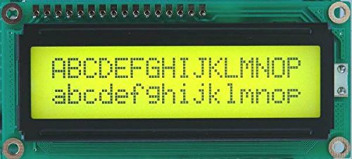
A LCD of two lines of 16 characters of matrix of 5x7 points. The driver includes a character generator in ROM with 192 characters and the possibility of defining another 8 in RAM. It also has a RAM of display data where the message to be displayed is stored of 80 bytes, of which 32 (2x16) are displayed.
Pins:
SIGNAL | PIN | FUNCTION |
DB0-3 | 8-5 | Low data nibble |
DB4-7 | 4-1 | High data nible |
E | 9 | LCD Enable |
R/W | 10 | Read / Write selector 1 Leer | 0 Escribir |
RS | 11 | Data or Instruction selector 0 IR | 0 DR |
VLS | 12 | LCD contrast, connect to potentiometer |
VDD | 14 | Power, 5v |
VSS | 13 | GND |
Operations:
The controller has two registers, the instruction (IR) and the data (DR), which are selected by the RS signal. These records can be read or written as indicated by the R / W signal, so that 4 different operations are possible:
RS | R/W | OPERATION |
0 | 0 | Write IR: Clean Display, etc., or modify AC. |
0 | 1 | Read IR: Read the AC(DB0-6) & the Busy Flag (DB7). |
1 | 0 | Write DR: Write on DD RAM or CG RAM |
1 | 1 | Read DR: Read from DD RAM or CG RAM |
Write to the IR: Instructions are sent and also to write a new address in the AC (Address Counter) register, which is the register in charge of pointing, both to the DD RAM (RAM of Display Data) and to the CG RAM ( Character Generator RAM)
Read from the IR: It allows the reading of the AC record, of which only the 7 least weight bits DB0-6 are valid, the May weight bit, the DB7, informs of the status of the Busy Flag or Occupied Display indicator.
Write in the DR: It allows writing in DD RAM or CG RAM where the AC record is pointed.
Read from the DR: It allows reading of DD RAM or CG RAM where the AC points.
Busy Flag (BF): A "1" indicates that the LCD is busy performing internal operations and can not accept new instructions. You have to wait for the Busy Flag to be "0" to send you the next instruction.
Direction Counter (AC): Indicates the address where the data on DD RAM or CG RAM will be read or written. This record can be modified by writing to the IR.
In addition, when writing or reading data in DD / RAM or CG RAM, the AC is incremented or decremented automatically according to the Entry Mode Set.
Display Data RAM (DD RAM): It has a capacity of 80 bytes, 40 for each line; Logically, only 32 of the 80 bytes can be displayed at the same time, although by moving the display you can display all the written characters.
Generator of characters in ROM (CG ROM): It has 192 characters, in matrices of 5x7 points.
Character generator in RAM (CG RAM): It allows to define 8 characters, whose codes go from 00 to 08, or from 09 to 0f.
 MATRIX KEYBOARD
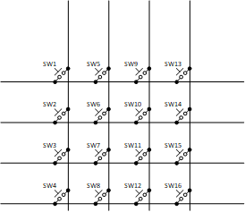
A matrix keyboard is one that has organized the connections of the keys in the form of n columns and m rows, such as a matrix.
They are done in this way, since with n + m connection lines you can read n x m keys. For example, a 16-button keyboard can be read with only 8 lines. However, this increases a little the complexity of the reading algorithm since it is necessary to do up to n readings m times to find the key pressed, that is, one reading per key. To facilitate reading we use an encoder MM74C922.
Encoder MM74C922: The keyboard encoders MM74C922 and MM74C923 CMOS provide the logic necessary to completely encode a matrix keyboard.
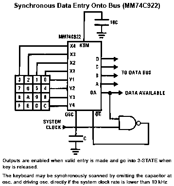
It has an internal bounce suppression circuit so the data output at high level, when a valid keyboard input has been made, is "clean". The available output data returns to a low level when the entered key has been released, even if another key is pressed. The available data will return to stop to indicate acceptance of the new key after a period of normal bounce suppression.
CODE IN HEX80
:03000000020040BB
:02000300211FBB
:02001300216E5C
:1000400075892175A885759840758DFD758BFDD2D4
:100050008E119811EB7590007D007E0078007C6019
:100060007A607B6079407530307531317532327528
:1000700033337534347535357536367537377538ED
:1000800038753939753A41753B42753C43753D4485
:10009000753E45753F4680FE11B3743811C1743802
:1000A00011C1743811C1740111C1740F11C1748070
:1000B00011C122758AB6758C3CD28C308DFDC28DF3...
Read more »


 teardownit
 Maarten Janssen
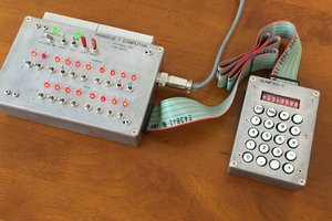
 Mitsuru Yamada