 Martin Hub
The project is using open-source BigClown kit for makers. Thanks to this it was easy to put all the functionality together. The pumpkin is controlled over MQTT. The MQTT command is send over reliable 868 MHz link thanks to the Radio Dongle. The pumpkin receives this command and sets effect, color or moves with the servo.
It works also the other way. The PIR Sensor sends event by radio which is translated to the MQTT topic. Also the temperature from the Core Module is reguraly sent.
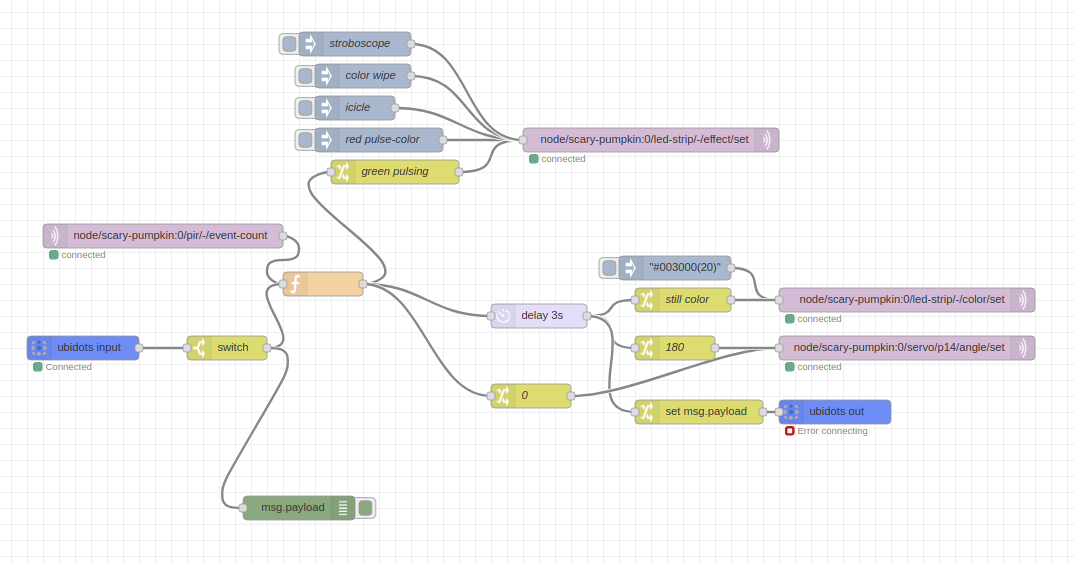
Thanks to this it's really easy to create a effect scenario in node-RED and add all the functionality like random colors, change intensity based on time, control effects from your phone from Blynk or Ubidots.
The rules are set in Node-RED. And can be very easily set on-the-fly.
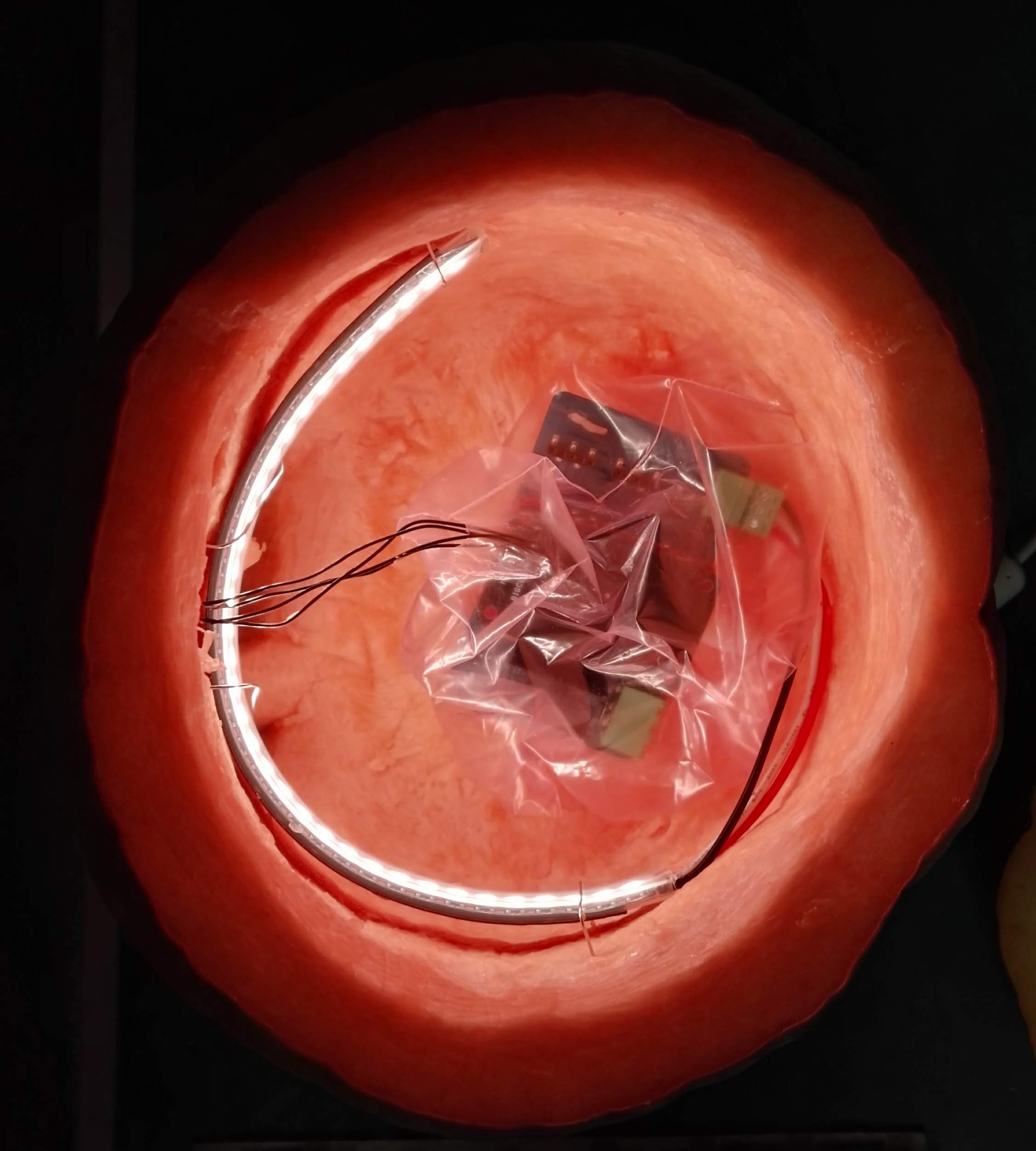
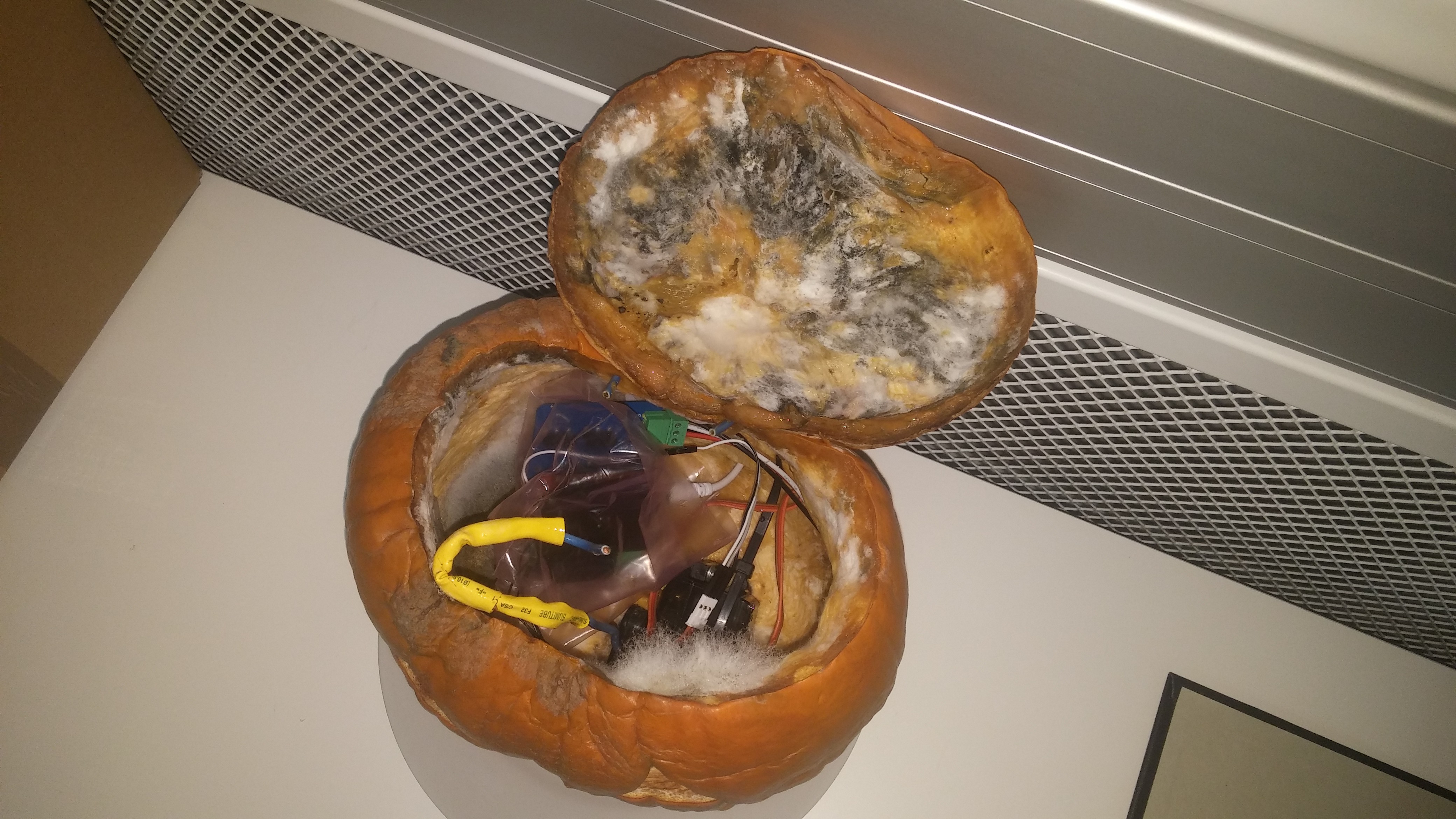
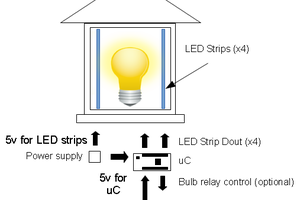
Here are the internals. 50 cm smart LED strip. In the middle Core Module that has the STM32L0 MCU + 868/915 MHz radio. The Power Module controls the LED strip.
 Neil Cherry
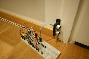
 Timo Hyvönen
 Jarich
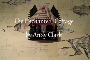
 Andy from Workshopshed