Features
- Electrical & characteristics: 12 V supply voltage. It should withstand 5 A phase current. For continuous operation, a heat sink will probably be required.
- Carrier board: Because an Arduino compatible uC board is simply too convenient.
- Custom PCB: Makes it simple to use SMD parts, and also I do not like soldering connections. Block commutation: Is simple to implement. It would be interesting to try modern schemes like space vector modulation and field oriented control. However, I learned about that after designing the hardware. So it is not supported.
- Speed control: Implemented by a PI controller. It takes a speed estimate and the desired speed and computes the pwm magnitude. The speed is estimated by measuring the time between state changes of the Hall effect sensors in the motor. I tuned the controller with some trial and error.
- Current limiting: One of the two ADCs is configured to measure the phase current during the “on” phase of the PWM cycle. If the current is larger than some threshold, the duty cycle is zerod for a brief period. The measurement is done over a current shunt on the low side and measures the total phase current.
- Digital communication via UART : I desire reporting of various quantities, like supply voltage, current, RPM, etc. Therefore a solution more sophisticated than the usual pulse position modulated signal was required. See below.
Switches
The half-bridges are built from PMOS on the high side and NMOS on the low side. Specifically:
- High side: IPD85P04P4-07
- Low side: IPD90N04S4-05
Furthermore, for robustness, the gate voltages are driven by dedicated chips. These sit between the MOSFETS and the micro controller. It seemed like a good idea to use such, rather than making level shifting circuitry from discrete components. I picked:
- Gate driver: MCP14A0155
These components were selected for low Ron and switching time between 0.1 and 1 us. But there are other specs that play a role, like breakdown voltage, price, package size and thermal resistance.
The average voltage applied to the motor is controlled by applying a 20kHz PWM signal to the high-side bridge, switching the corresponding coil between Vbat and Gnd. Which bridge is currently high-side is determined by the block commutation scheme, depending on the rotor position.
Communications
Sending and receiving raw bytes via UART or USB is trivial with the Arduino API. Furthermore, I use
- Protobuf: For (de)serialization of messages. The protobuf compiler conveniently generates an API for each message definition. There is an implementation suitable for micro controllers called nanopb.
- COBS framing: Protobuf does not handle framing, i.e. providing information about the start and end of a message in the raw byte stream. I chose the COBS method to do that.
I am aware of MavLink. However, I am familiar with protobuf. Hence my choice.
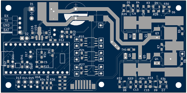
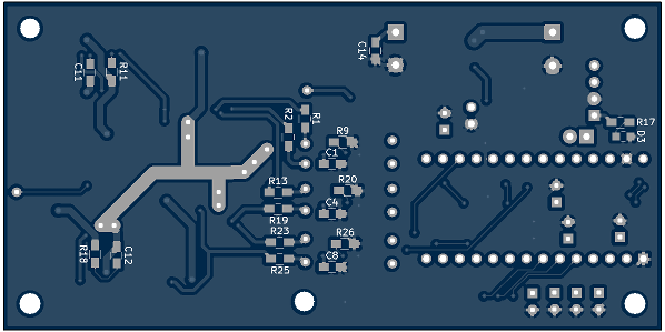
Schematics
The design was done in KiCad. Files are on Github
The PCB
Generously sized … The area on the right is intended to allow mounting a standard PC chipset heatsink on the MOSFETS.
The Code
On Github. It might not be the best structured or most readable. I do some low level control register manipulation. So be warned.
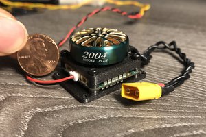
Results
Well, it drives my RC car around.
Limitations
- Only tested under light loads, while driving indoors.
- Hardcoded paramters
- Little regard for fail safety.
- Current limiter is pure software implementation, and therefore slow.
 Christopher Xu
 SUF
SUF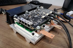
 Marcos
 Simone Tolomei