Mike Teachman
-
Modular Design Concept
06/02/2019 at 21:56 • 0 commentsIt's time to transform the Street Sense breadboard implementation into something more permanent. Over the next month my ambition is to get all of the electronics and sensors into a weatherproof enclosure so I can start some field trials
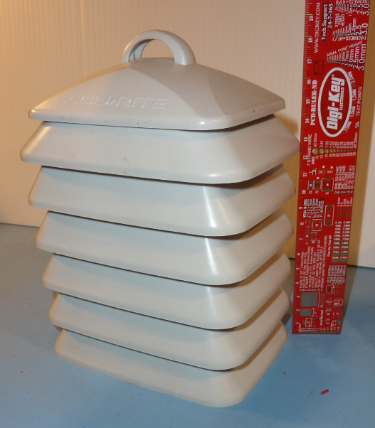
The selection of the enclosure wasn't difficult. I'm going to house the electronics in the same enclosure used in the SensorUp Smart City Starter Kit. I am a participant in the SensorUp Smart City pilot project and have a one of their beta sensor units mounted on my back porch, measuring PM2.5 particulates, since August 2018. My measurement site is called "Fernwood" in the air quality map of Victoria. This enclosure seems to work well. My only issue was a spider that nested inside the enclosure. The SensorUp enclosure is a commercially available unit, made by AcuRite.
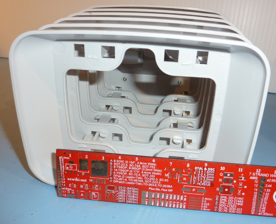
The sensors and electronics will be located inside the enclosure cavity. The dimensions of the cavity are:
Bottom opening: 5cm x 9cm
Depth: 12cmPackaging Goals:
- Protect electronics and sensors from wind and rain.
- Allow airflow across sensors
- Removal of electronics as a single unit, to facilitate desktop development.
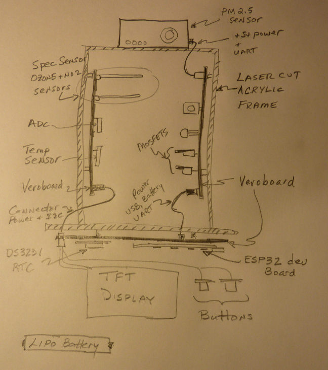
I would like to build some sort of carrier frame, to mount the electronics, that would fit inside the AcuRite enclosure cavity. Here is a paper prototype sketch of the carrier frame for the electronics and sensors.
3 circuit boards are planned, implemented with veroboard:
- Ozone + NO2 sensors, ADC, power conditioning for sensors
- Power conditioning for PM2.5 sensor
- Processing board. ESP32 + RTC
The Lipo battery needs to go somewhere as well. Not sure where it will be located at this time.
The frame will likely be constructed with acrylic, laser cut at Victoria Makerspace, where I am a member. The 3 circuit boards will be attached to the frame with standoffs and bolts. Then the whole assembly will slide into the cavity of the AcuRite enclosure. Some sort of latched attachment mechanism needs to be conceived to securely hold the frame to the AcuRite enclosure - another TBD design topic.
-
Improving Ozone and NO2 Sensor Performance
05/14/2019 at 17:07 • 0 commentsThis project update outlines some incremental improvements to the ozone and NO2 sensor performance.
A separate analog power supply was created on the breadboard to provide 3.3V to the ADC and Spec Sensor modules. The idea is to isolate these sensitive analog components from the noisy 3.3V digital power supply. The battery provides power to the input of an ultra-low dropout linear regulator which then feeds the ADC and Spec Sensor modules. Luckily, the combined current consumption of the Spec Sensor modules and ADC are low enough that the Lolin D32 Pro battery charging circuit is not affected. The analog power supply circuit can be found in the version 8 schematic.
The method of reading the sample values from the ADC is another significant change. Previously, the ADC was polled using I2C in single-shot mode to detect every new sample. The polling with I2C was factor in creating unwanted noise into the Vgas outputs of the Spec Sensors. This noise was appearing while the ADC was performing the conversion - not good. Now, the ADC runs in a continuous conversion mode and the ~DRDY signal is used to run an ISR in the MicroPython code. The ISR reads the sample value. This is arrangement is better for two reasons:
- I2C polling during ADC conversion is eliminated = less noise is seen by the sensitive op-amp circuits in the Spec Sensor modules
- The MicroPython code is more efficient - no more polling is need to detect the end of ADC conversion
The MicroPython code for this change is documented with this github commit.
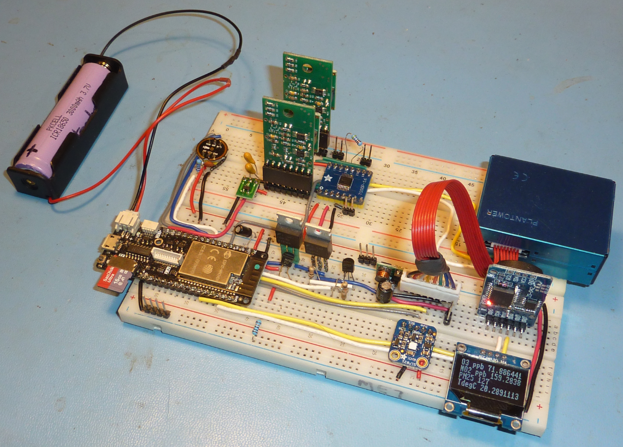
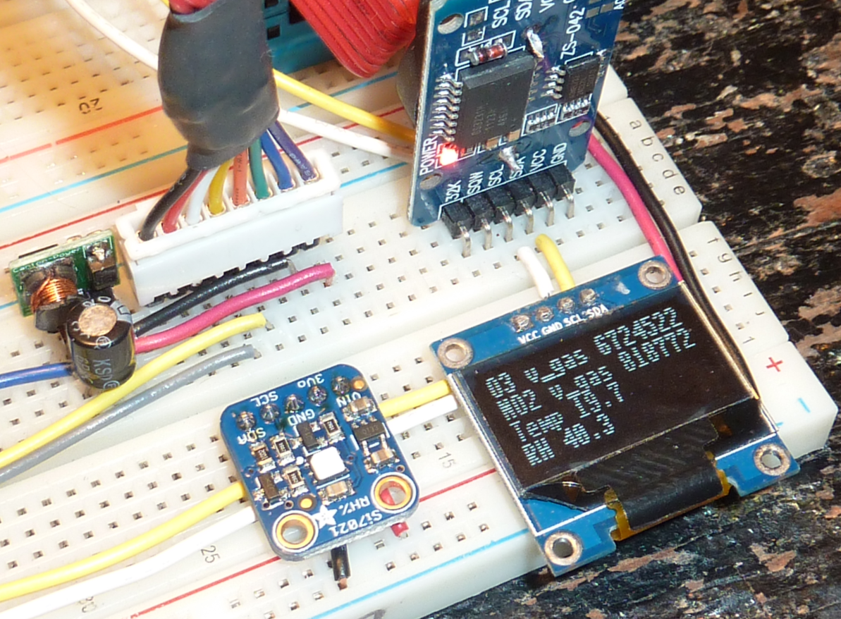
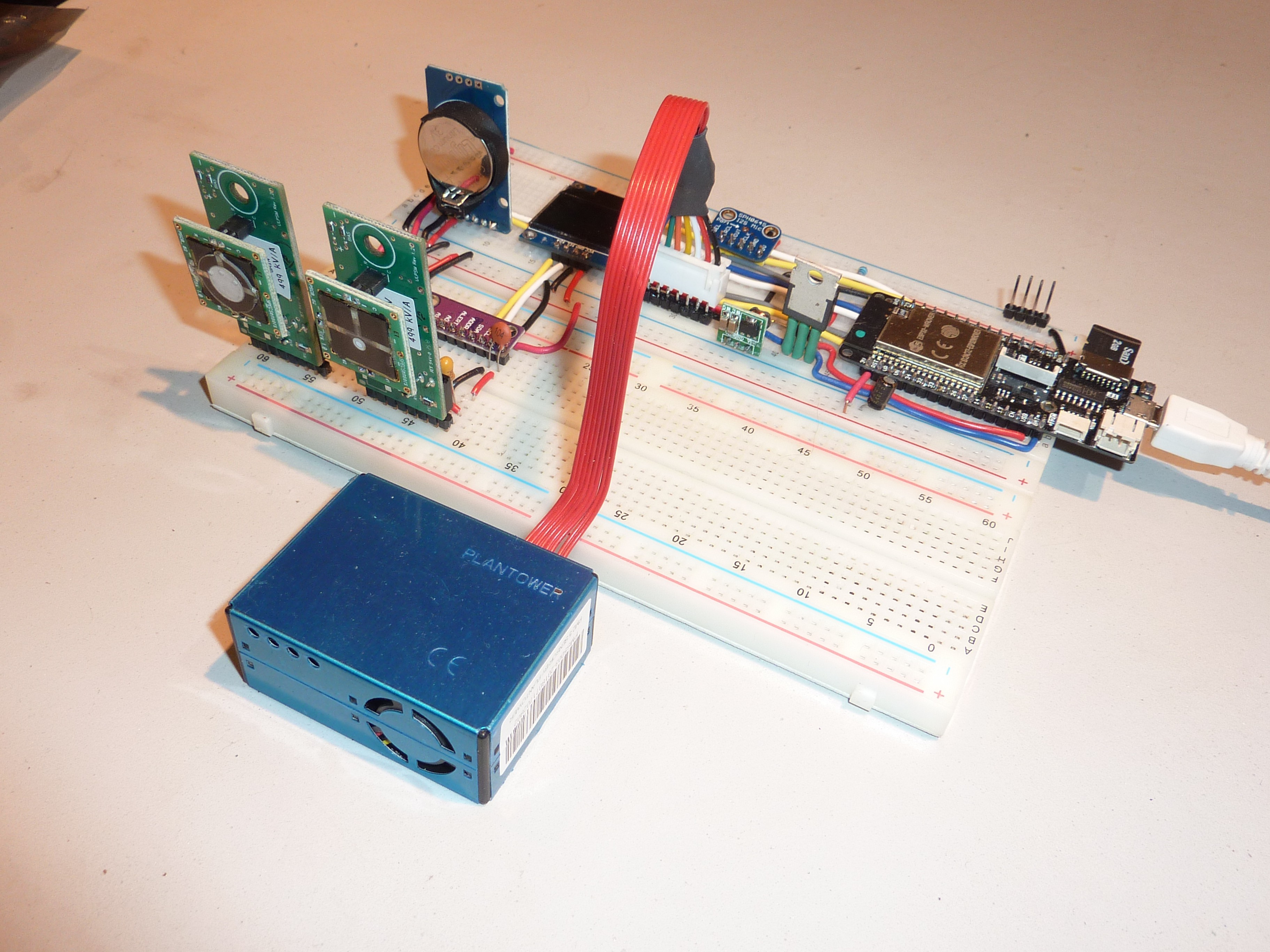
Here is what the breadboard prototype looks like now. You'll spot the new voltage regulator which sits just below the two orange tantalum capacitors.
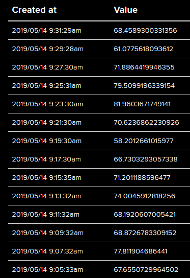
Here are some ozone measurements that were published to Adafruit IO using the MQTT protocol, every 2 minutes. The units are parts-per-billion (ppb). The goal is to have a resolution of 10ppb. You can see that the readings still bounce around. It is significantly better with the changes. But, there is still work to be done to improve measurement stability.
These latest changes seem like the end-of-the-road for improvements to the breadboard prototype. Breadboards have so many other limiting factors such as capacitance between metal connection strips and stray inductance. Future improvements in sensor measurement performance will need to come from other means, such as soldered connections and likely a custom PCB.
-
Publishing sensor data with MQTT
04/07/2019 at 18:47 • 0 commentsThe next iteration of the prototype involves taking advantage of the built-in WiFi feature of the ESP32 microcontroller to publish sensor to an internet database such as Adafruit IO or Thingspeak. The MQTT protocol will be used.
Publishing data to a cloud database with WiFi and MQTT protocol is something I've done in other projects. But, there is an added technical challenge in this project - that is publishing data and simultaneously recording audio to SDCard without creating audio gaps. If the MQTT task blocks for too long at any point, the DMA buffering used in by the audio recording task will "overrun" leading to gaps in the recorded WAV file.
To overcome this risk I used a non-blocking asyncio version of MQTT written by Peter Hinch. This version uses a non-blocking sockets implementation and will not block other asyncio co-routines from running (like the microphone recording task) when WiFi goes down or the MQTT broker is unreachable. An additional pause/resume feature was added by Kevin Köck that allows WiFi to be turned off when the device is not actively publishing. This turns off the WiFi radio which reduces the power consumed by the ESP32 - the end result is a longer battery life. There is a discussion on the MicroPython forum describing how this enhancement was realized. Sensor data will be published every 15 minutes in the final design.
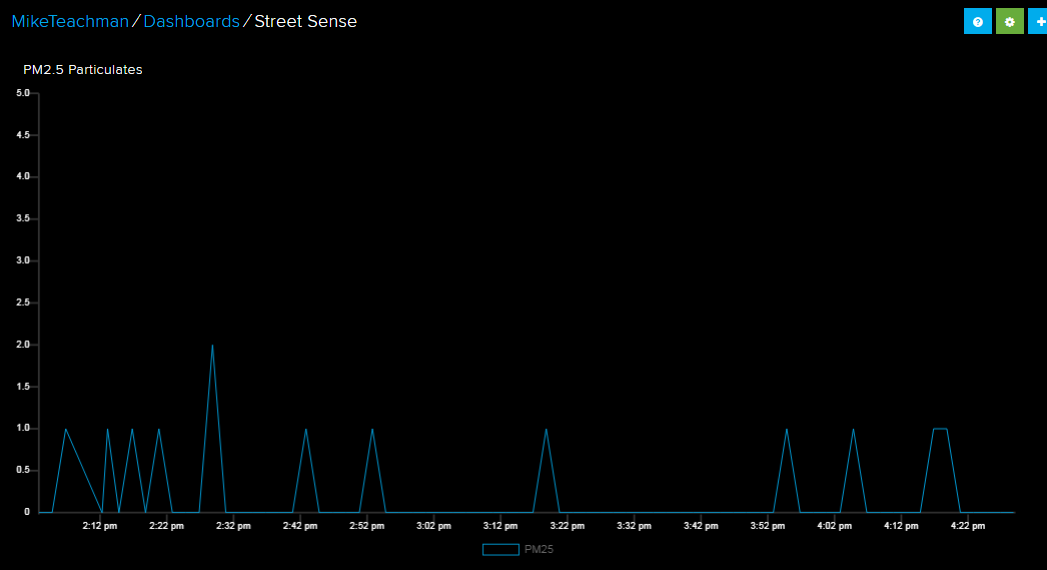
A 2 hour test was run, publishing sensor data to Adafruit IO. Below is a plot from Adafruit IO showing 2 hours of PM2.5 particulate data. This shows a very clean air day on the west coast of Canada! This publish period was reduced to 2 minutes for this test.
Some diagnostic information in the microphone task showed that there were two audio gaps in the 2-hour SD Card audio recording. The was a unwelcome result. More debugging code will be needed to determine the root cause of the audio interruption. The audio sample rate in the test was 10kHz.
-
Temperature and Humidity Sensor
03/25/2019 at 17:20 • 0 commentsThe next step in the project is rather unremarkable - adding a temperature and humidity sensor. I chose the Si7021 sensor, packaged in a convenient breakout board by Adafruit. The sensor specification claims ±0.4 °C temperature accuracy. Temperature measurements from the sensor will be recorded periodically to the SD card and will be used for temperature compensation of the ozone and NO2 sensor readings.
I have used this breakout board in other MicroPython projects so I was expecting a simple integration with the Street Sense MicroPython code. But, I once again stumbled on a breaking interface change in the Loboris ESP32 port. The Si7021 driver that I use with the mainline of MicroPython does not work in the Loboris port - caused by a breaking change in the I2C interface API.
Fortunately, I was able to source a different Si7021 MicroPython driver from Github for this sensor that works with the Loboris I2C implementation.
The V07 schematic shows the addition of the sensor.
The sensor is mounted in the breadboard to the left of the OLED display
-
New I2S Microphone
03/20/2019 at 15:52 • 3 commentsIt turns out that the Adafruit I2S MEMS Microphone breakout board does not work properly with ESP32 microcontrollers. The Adafruit breakout board uses the SPH0645LM4H MEMS microphone.
What's going on? I have discovered a timing incompatibility between the ESP32 and the I2S microphone - the ESP32 samples data on the rising edge of the I2S clock, exactly the same time as the sample data is changing from the SPH0645LM4H microphone. The unfortunate end result is that every 18-bit sample from the microphone is shifted one bit to the left - the MSB is lost and a '0' appears as the LSB.... not good.
A couple of years ago this issue was discussed on an Adafruit forum...but no real answer came out of it.
Let's take a deeper dive to see what is happening.
The ESP32 Technical Reference Manual describes the expected timing between WS, BCK, and SD
"WS and SD signals in the I2S module change on the falling edge of BCK, while the SD signal can be sampled on the rising edge of BCK"
The key part is "sampled on the rising edge of BCK".
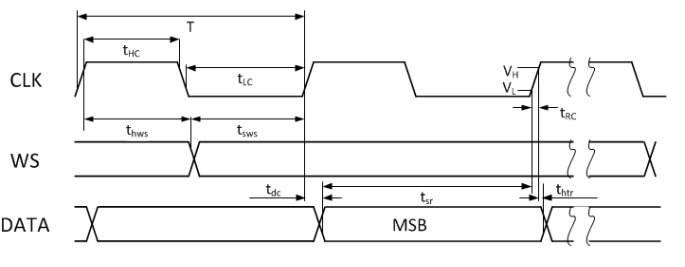
A timing diagram in the ESP32 Technical Reference Manual shows the expected timing for an I2S slave device. Shown below:
The SPH0645LM4H device implements the timing diagram shown below. Notice that DATA (SD) transitions on the rising edge of CLK.
The SPH0645LM4H datasheet specificies a Max Tdc = 65.92ns, but surprisingly no Min value for Tdc.
This doesn't look like a good situation - data changing when it is being sampled is not a recommended design practice !
The captured sample data clearly shows a problem -- the data shows that the ESP32 uses the MSB of the Left channel as the LSB of the Right channel. That line I just wrote is likely confusing! Let's look at an example to get clarity.
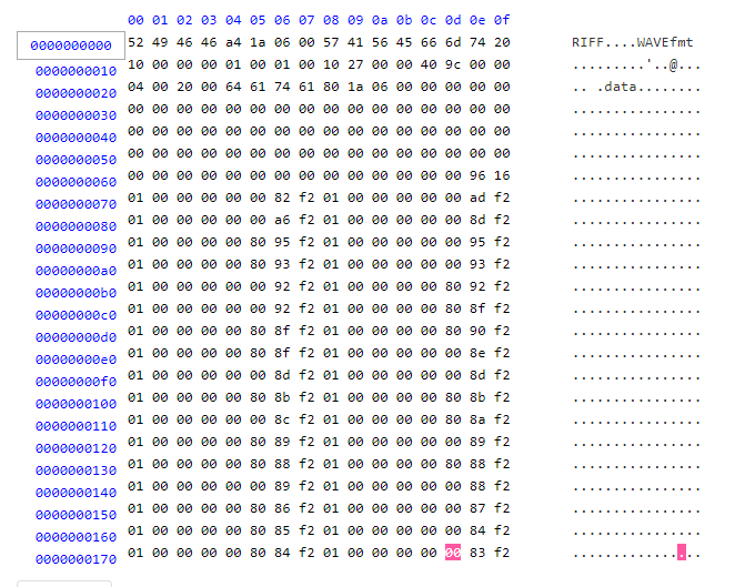
The WAV file data shown below was captured using the ESP32 I2S interface. The "0x01" value bytes that appear in two columns are the least significant bytes for the Right channel. They should be 0x00 as the microphone is configured to only output sample data on the left channel (WS=low). But they are 0x01 because the MSB of the Left channel is clocked in as the LSB of the Right channel by the ESP32. A sharp eye will notice that every Left channel sample has the LSB equal to zero (e.g. always 0x80 and 0x00...never 0xC0 or 0x40) - that happens when the "19th" bit (which is pulled down to zero when the data bus goes tri-state) is sampled as the LSB "18th" bit. Note that the data is in little endian format.
![]()
I was able to use an oscilloscope to capture the I2S data bit stream that is associated with the above WAV file. The scope capture below shows BCK, WS, and SD (top to bottom) of the 2nd non-zero audio sample. The bit stream on the SD signal shows a sample value of 0xF9 0x41 0x00 0x00. Now, compare to the 2nd Left channel sample in the WAV file above (in line starting with 0x70) which has a value = 0xF2 0x82 0x00 0x00 (converted from little endian)
if you take sample = 0xF9 0x41 0x00 0x00 (the "correct" value seen in the bit stream) and shift it L by one bit you get sample = 0xF2 0x82 0x00 0x00 (the "wrong" value sampled by the ESP32) which is seen in the WAV file data.
![]()
This shows the compatibility problem between the ESP32 I2S interface and the SPH0645LM4H microphone.
I was hoping for a workaround. But, I could not find a means to adapt the timing of either the microphone or the ESP32 to make them compatible. There is a (complex) firmware solution where the undesired bit shift can be undone. I did not pursue that approach.
A simple solution involved changing to a different I2S microphone breakout board using timing that aligns with the ESP32 - the INMP441 I2S MEMS microphone seems like a good match. The datasheet shows that the INMP441 device has I2S timing expected by the ESP32.
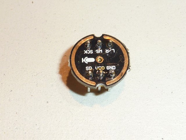
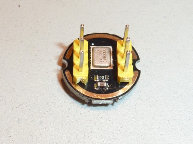
I found an Asian supplier that offers this I2S microphone in a breakout board. Here are photos.
![]()
![]()
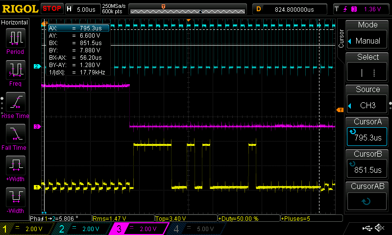
An oscilloscope capture shows that this microphone will work with the ESP32 I2S interface. Notice that SD (purple) changes on the falling edge of BCK (yellow). The ESP32 samples on the rising edge of BCK, in the middle of each sample bit.
![]()
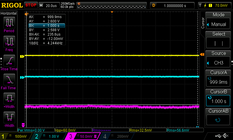
End result: The audio sample data captured by the ESP32 using this new I2S microphone is correct.
-
New ADC
03/18/2019 at 16:17 • 0 commentsA new Texas Instruments ADC was added to the design -- ADS1219
The ADS1219 replaces the ADS1015 ADC. This new ADC offers these benefits:
- integrated input buffers -- allows measurement of high impedance inputs such as Vref coming from the Spec Sensor devices
- separate inputs for analog and digital power/ground -- allows more options to mitigate power supply noise
- better noise-free resolution than either of the ADS1015 or ADS1115 ADCs
I wrote and published a MicroPython driver for the ADS1219 device. The control of the device in MicroPython was quite simple.
The V05 schematic includes the new ADC. You will notice that the initial integration of this ADC is lacking most sensible approaches to minimize noise effects:
- 3.3V digital rail supplies analog power for both the ADC and Spec Sensor gas sensors.
- ADC soldered to a TSSOP-16 breakout board and then plugged into a breadboard
This approach allowed me to write the MicroPython driver and get the device integrated into the rest of the MicroPython code.
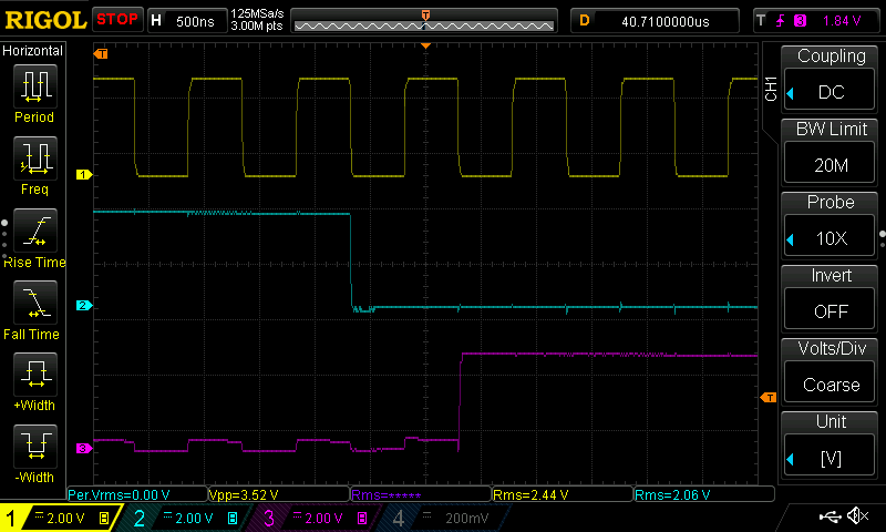
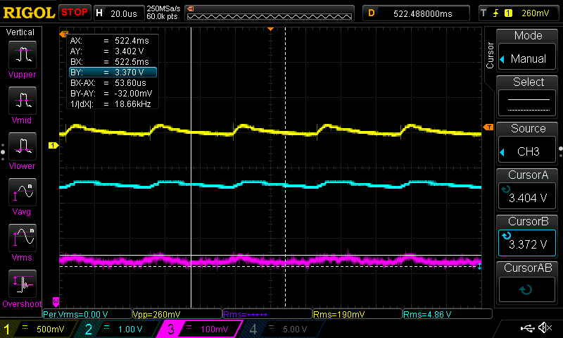
Given the lack of care to deal with power supply noise, it wasn't surprising to see poor results when reading the analog values from the ozone and NO2 sensors. Results showed considerable variability in back-to-back measurements for gas concentration. An oscilloscope capture shows that the Vgas outputs from the gas sensors oscillate during the time they are being sampled by the ADC.
- yellow = Vgas Ozone
- aqua = Vgas NO2
- purple = 3.3V rail
You can see voltage fluctuations on the 3.3V rail that are associated with the oscillations. These oscillations happen each time the ADC performs a single-shot conversion.
![]()
Next steps: Time to put on the analog design hat and investigate decoupling methods to provide low-noise analog power for the ADC and gas sensors.
-
Taming Noise From the Boost Converter
03/14/2019 at 23:07 • 0 commentsThe PM2.5 particulate sensor requires a 5V supply voltage. Supplying this 5V requires special consideration when the unit is powered by a 3.7V Lipo battery. Providing 5V of power with a 3.7V battery is accomplished using a type of switched-mode power supply called a boost converter. The boost converter used in this design is built around the ME2108 IC.
Switched-mode power supplies are notorious for injecting noise into circuits. I investigated this concern.
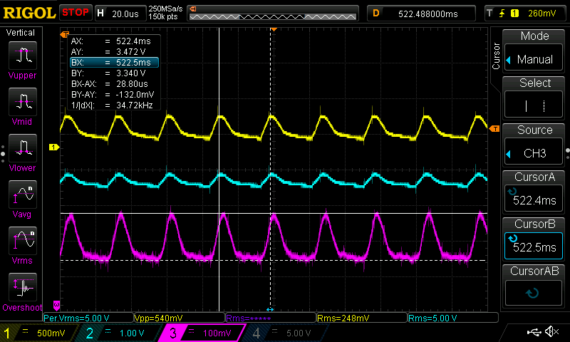
The purple trace in the scope capture below shows noise on the 3.3V rail -- measured as 132mV with a frequency of 34.7 kHz. As a quick test, I removed the boost converter -- the 3.3V rail noise dropped dramatically - this shows that the boost converter is a significant source of noise.
![]()
Many devices, including a noise-sensitive ADC is powered with the 3.3V rail. My first results with the ADC are not encouraging - I see unstable results from the ozone and NO2 sensors. I suspect that the switched-mode supply noise is contributing to the undesirable results.
The first mitigation step was to replace the 1N4001 diode in the USB/Battery selection circuit with a Schottky diode. A Schottky diode is recommended for this circuit. I found two types of Schottky diodes at our local Makerspace and chose the diode that reduced the noise the most.
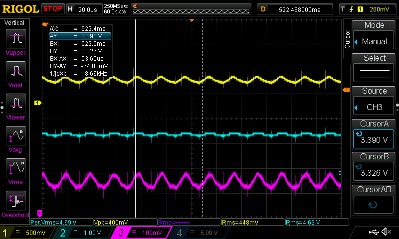
Adding the Schottky diode produced measurable improvements - noise was approximately halved. Shown in the scope capture below.
![]()
Adding a 220uF electrolytic capacitor to the input of the boost converter produced more measurable noise improvements on the 3.3V rail. Apparently electrolytic capacitors are not the first choice capacitors for the input of boost converters (low ESR ceramic capacitors are preferred). However, the electrolytic capacitor reduced the noise on the 3.3V rail by an additional 50% , shown below.
![]()
Lastly, I added a high-side MOSFET switch to turn off the boost converter using a GPIO pin on the ESP32 microcontroller. The particulate sensor only needs to be powered-up on demand to make a periodic measurement. When the boost converter is switched off the noise on the 3.3V rail is reduced further.
![]()
These improvements are reflected in the latest V4 schematic release, link below.
-
Ozone and NO2 sensors
02/13/2019 at 22:16 • 2 commentsWith the I2S microphone and particulate sensors working well, the next step is integrating the ozone and NO2 sensors. These sensors are manufactured by Spec Sensor and are used in the Array of Things project in Chicago. Spec Sensor published a report showing that the Spec Sensor units perform well in side-by-side tests against calibrated industrial-grade sensors. The credibility of these sensors appears promising.
I chose the analog module versions for both the ozone and NO2 sensors. The modules include all the difficult analog amplification and biasing circuitry. I have little of that skillset - it was an easy decision to purchase units that include the analog sub-circuits.
Each sensor has an analog output, 0-3.0V range, that is proportional to the measurement of gas concentration. This analog output will be converted to digital using an analog-to-digital converter (ADC) device that will connect to the ESP32 using an I2C bus. In my parts stock I have the ADS1015 ADC by Texas Instruments. It has 12-bit resolution and can operate with a 3.3V supply. I like using ADCs having an I2C communication interface as it allows the ADC to be located in immediate proximity to the sensors This allows short analog signals runs, thereby reducing coupled noise. The ESP32 has some built-in ADCs, but reports are not flattering on the performance. I might use these ESP32 ADCs for non-critical operations like reading battery voltage.
Each sensor module has 3 outputs that can be measured. Vgas, Vref, and Vtemp. Vgas is the important one - the analog reading which represents the gas concentration. It wasn't too clear on how the other two outputs are used. I contacted the company and got a prompt response. Spec Sensor indicated that good results can be achieved using only the Vgas output. The other two outputs are high impedance outputs which are somewhat difficult to use with ADCs.
I expanded the breadboard prototype to include the two gas sensors and the ADC. The gas sensors and ADC are shown in the left side of the photo below. The V03 schematic is up-to-date with these new devices.
![]()
The ADS1015 device is quite popular and there is a MicroPython driver available. Unfortunately, the driver needed some small modifications as the I2C implementation on the Loboris MicroPython port introduces breaking changes compared to the mainline of MicroPython. It's frustrating when a fork of a project does not maintain backwards compatibility with key interfaces like I2C.
Two new co-routines were added to the Street Sense MicroPython code to manage the two sensors. The raw sensor values are displayed on the OLED display and are logged to the SD Card.
What about results? I observed that the gas values are not as stable as I expected. I modified the driver configuration to select a slower sampling rate and the values become more stable. But, still not what I need for the final unit.
From my long 25 year career in measurement at Schneider Electric Victoria I knew that this stage of the project would be toughest to crack. This is just the first step in what will be an iterative design. I fully expect to try out a few ADCs, add filter capacitors, and who knows what else -- to get a stable and accurate digital representation that fully exploits the accuracy of these gas sensors. Perhaps I'll need to seek some help from my ex-colleagues who are unbelievable world-class experts in analog design?
One area that needs work is ADC resolution. The ADS1015 devices have 12 bits of resolution. That is good enough for some prototyping, but my calculations show that 12 bits is inadequate for the resolution of the Spec Sensor devices.
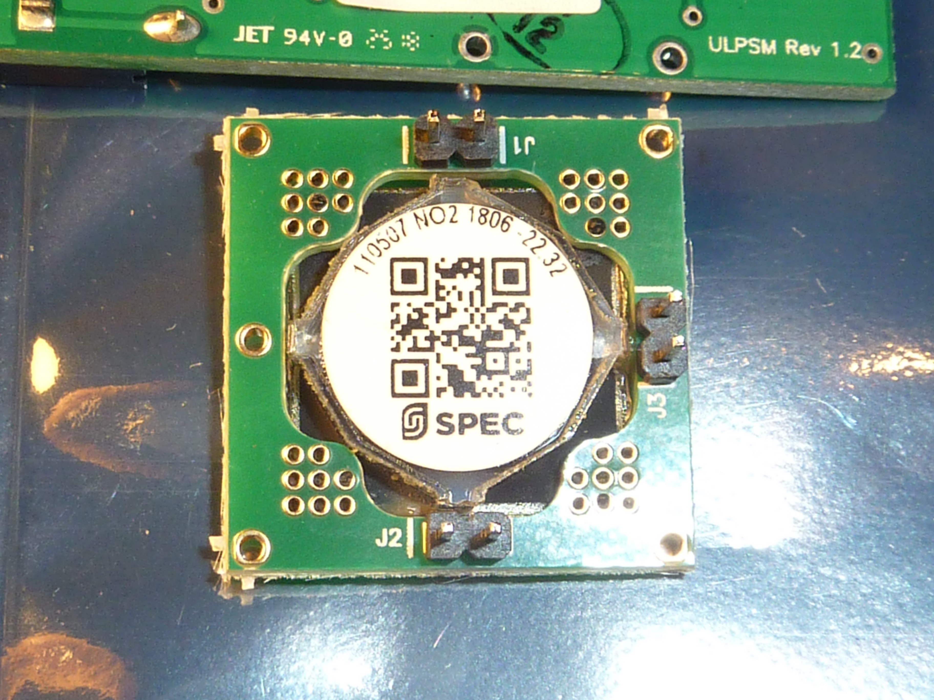
The Spec Sensor devices have a resolution better than 20 ppb (ppb = parts-per-billion). The datasheet of each sensor indicates a formula to calculate V/ppm. V/ppm is needed to determine the ADC resolution that is needed. Each sensor is has a factory accuracy constant called a "sensitivity code" that is used in the formula. For example, the sensitivity code on the NO2 sensor is -22.32, shown below:
![]()
Using the manufacturer's formulas I calculated the analog voltage change resulting from a 20ppb change in gas concentration.
The ozone sensor voltage changes by 0.4358 mV for each 20ppb, while the NO2 sensor voltage changes by 0.2228 mV for each 20ppb change.
Looking at the NO2 sensor. The output range is 0-3V. The minimum number of ADC steps needs to be 3000 mV/0.2228 mV = 13464 steps. It is quick to determine that a 12 bit ADC with 4096 steps is not capable of delivering this resolution.
I did some Digikey hunting for an appropriate I2C based ADC and found the ADS1219 device, a 4-channel, 24-Bit resolution ADC. The price point is below $10 per single unit. The Applications section of the datasheet even calls out "Gas Detectors" and the device includes buffers that allow connection to high-impedance sources (like the Vref or Vtemp outputs from the gas sensors). Promising...
The ADC parts were ordered at 8am this morning with delivery estimated for 5pm tomorrow. Digikey = great customer service (at least in all my experiences ...)
Undoubtedly, lots more to come on this topic !
-
Improving microphone handling with Fast IO
12/28/2018 at 17:43 • 0 commentsThe previous log outlined some concerns with microphone handling delays caused by delays when the loop yields to the uasyncio scheduler (e.g. the measure delay of 6ms). I explored the use of an alternative uasyncio library called Fast IO. The Fast IO library adds a high-priority I/O queue to uasyncio. This allows a coroutine to be given higher priority than other coroutines that are waiting to run.
I changed the microphone coroutine to use this high-priority queue and ran some performance tests. The change was done in one line - I used a high-priority millisecond timer in place of the the standard uasyncio sleep timer. Using this new timer results in the microphone loop getting scheduled in a high-priority queue -- the microphone loop will run before any of the other coroutines.
With this change the yield time in the microphone handling loop was reduced by about 20%. More importantly, the change insures that the time-critical microphone handling loop always gets priority over other waiting coroutines. This will greatly reduce the risk of overruns in the received DMA sample buffers.
-
Performance Concerns
12/15/2018 at 06:00 • 0 commentsMy previous log discussed the Asynchronous programming approach being used in this project.
As a quick reminder, the key concept of Asynchronous programming is co-operative scheduling of coroutines that need processing time. Each coroutine is "trusted" to only run for a minimal amount of time, then give control back to the scheduler, so that other coroutines can run... very cooperative and nice.
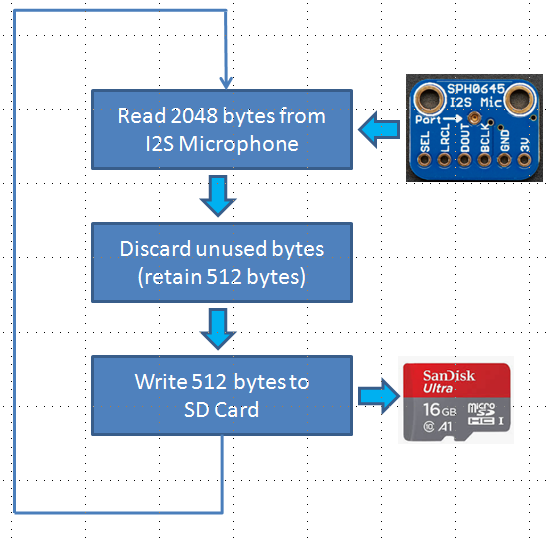
The ambition for noise analysis is to record a gapless stream of audio samples to an external SD Card that can be later post-processed and characterized. The high level functions in the audio processing loop are shown below.
This flowchart depicts a continuous loop that is 100% dedicated to audio sample processing. But, the sensor unit has other tasks that need to run. For example, there are tasks that need to read the ozone, NO2, and PM2.5 particulates sensors. There is a display task to update the OLED display. And, eventually there will be a MQTT task pushing sensor readings to the cloud. If the audio loop ran continuously, no other task could ever be serviced.
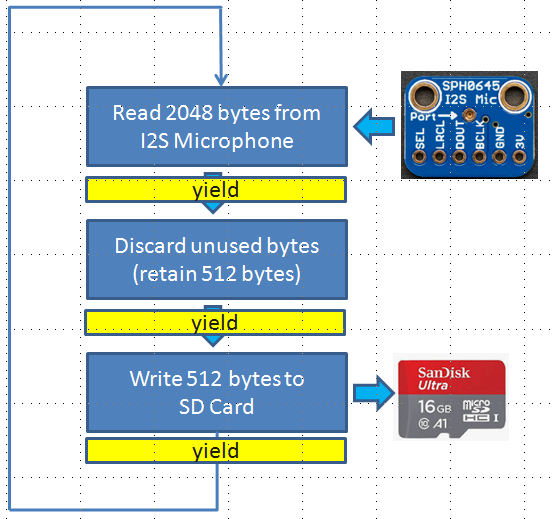
With asynchronous programming, a coroutine that runs in a loop must periodically give control back to the scheduler so that other tasks can run - this is called a yield. Control is yielded to the uasyncio scheduler using a call to await asyncio.sleep(0). Three yield points in the microphone handler are shown below.
Problems !
The 3 yield calls were added to the loop and an audio recording was made using a 20 kHz sampling rate. The audio playback showed "choppy audio", indicating gaps in the recording. What is happening?
First, some background on constraints in the processing of audio samples
1) Every loop, 256 audio samples are read from the microphone. If the sampling rate is 20kHz, the sampling period is 256/20kHz = 12.8 ms. On average, the microphone loop needs to complete every 12.8ms. Otherwise, samples will be missed.
2) Audio samples are first buffered into a chain of DMA memory blocks. There are limitations in DMA buffering. A total of 16 kBytes of DMA memory is used to buffer the incoming audio samples. That amount of buffering can hold 102.4 ms of samples. This means that the microphone loop can be blocked from running a total of 102.4 ms in the worst case. If it is blocked for longer, then the DMA buffer will overrun and samples will be lost.
I added some print() statements into the loop to better understand the time of each operation. The unexpected surprise was the await asyncio.sleep(0) call. This call gives control back to the scheduler, giving other tasks the opportunity to run (if they are ready). I expected that the call to await asyncio.sleep(0) would return very quickly (e.g. < 1ms) when no other tasks are queued to run. This is not the case. It took a typical 6 ms to return control back to the audio processing loop even when no other tasks were queued to run. What's the big deal? - 6 ms is a blink in time. But, it represents a rather high percentage of time for the overall audio sample processing loop time (12.8ms), especially if 3 calls to asyncio.sleep(0) are made in each loop.
Only having one call to asyncio.sleep(0) eliminated the gaps in the recording. Still, this amount of "wasted" time in the scheduler is concerning. When the microphone task yields to the scheduler more than one task may run. If every task switch takes 6ms I have doubts that gapless audio recording is feasible with uasyncio.
At this point, I'm having thoughts like "I should do this project in C/C++" which I believe would eliminate these inefficiencies. But, I'm still fairly committed to a MicroPython implementation - it's just so liberating to use this rich language and skip the time-sucking compiling phase.
The hope
I posted my design issues to the MicroPython forum and received some good feedback. I learned that there is an alternative implementation of the MicroPython uasyncio library called fast_io. Fast_io has a modified scheduler that can give priority to critical tasks, like the audio sample processing task.
The next step is to evaluate the fast_io library. More soon ...
Street Sense
Portable electronic device to measure air and noise pollution