0%
0%
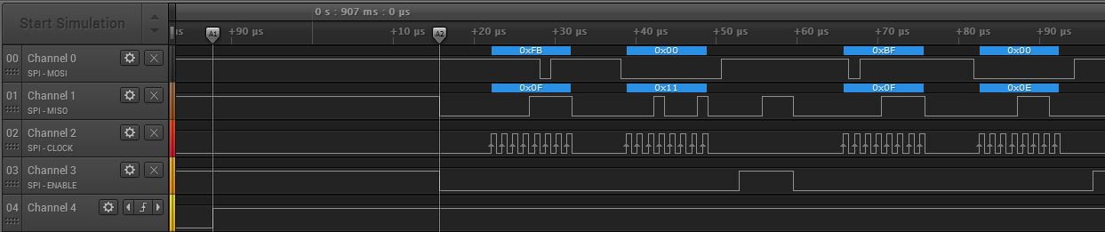
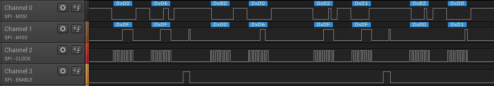
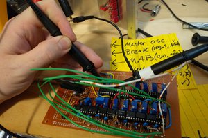
Philips LivingColors gen1 WiFi addon
Add an ESP8266 to a Philips LivingColors gen1 to control it over WiFi without losing the ability to control it with the remote
 Stefkuhb
Become a Hackaday.io member
Already have an account? Log in.
Just one more thing
To make the experience fit your profile, pick a username and tell us what interests you.
Pick an awesome username
hackaday.io/
Your profile's URL: hackaday.io/username. Max 25 alphanumeric characters.
Pick a few interests
Projects that share your interests
People that share your interests

 schlottmachine
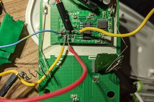
 Kaili Hill