 Tobias
Schematic:
(Check the pdf in the files section for better quality.)
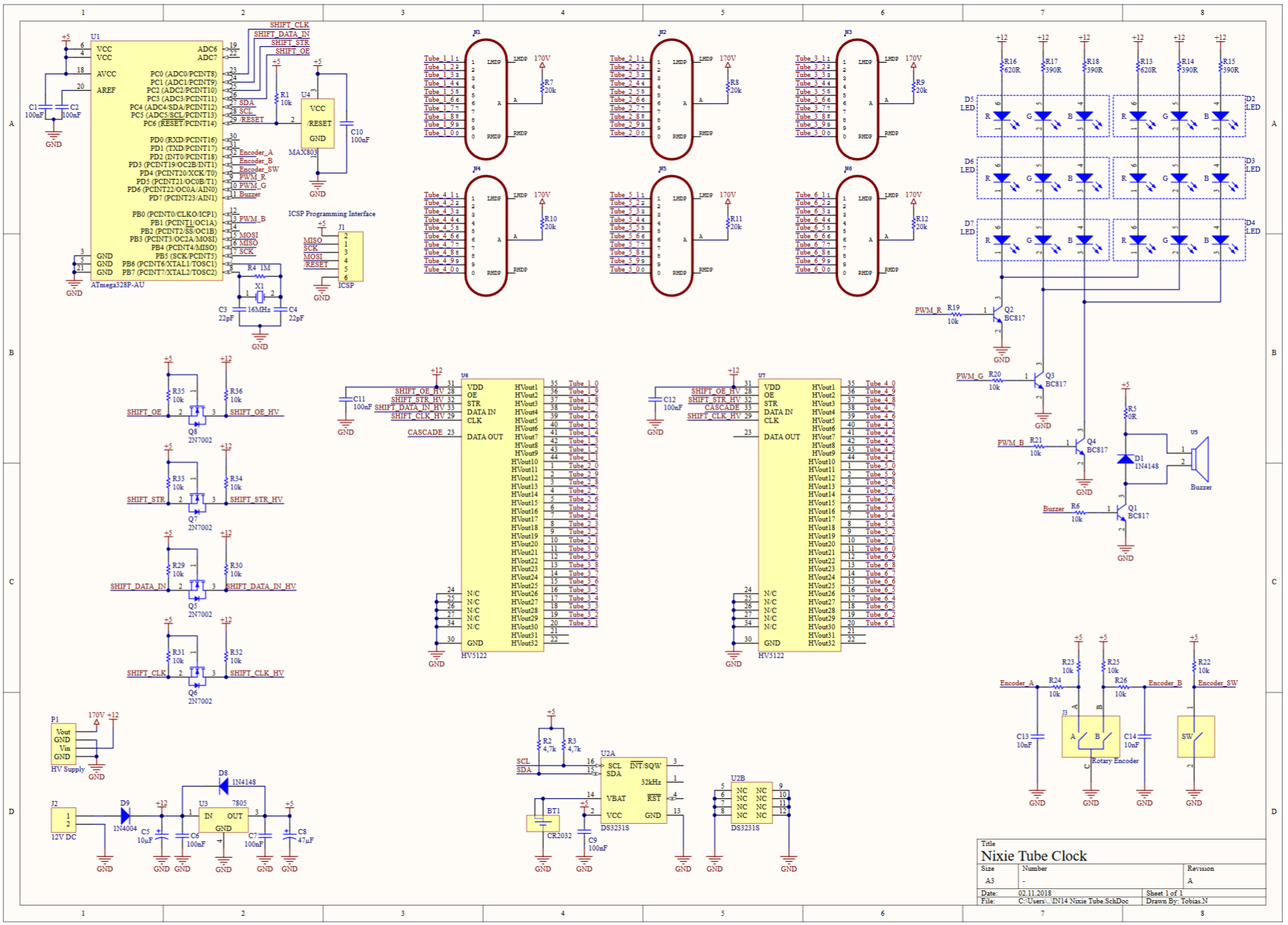
The clock is powered by a 12V wall adapter. For the IN-14 nixie tubes I used a seperate 170V high voltage power supply, which is mounted below the main PCB and connects via 4 wires.
The rest of the circuit is pretty simple, the µC controls the RGB LEDs, buzzer and the 2 32-bit shift registers for the nixie tubes. Since the shift registers run on 12V I'm also doing some levelshifting for the control signals. For the RTC I went with the popular DS3231 again, since it's basicly the perfect device for this kind of application.
In order to interact with the clock, I'm using a rotary encoder with pushbutton.
PCB:
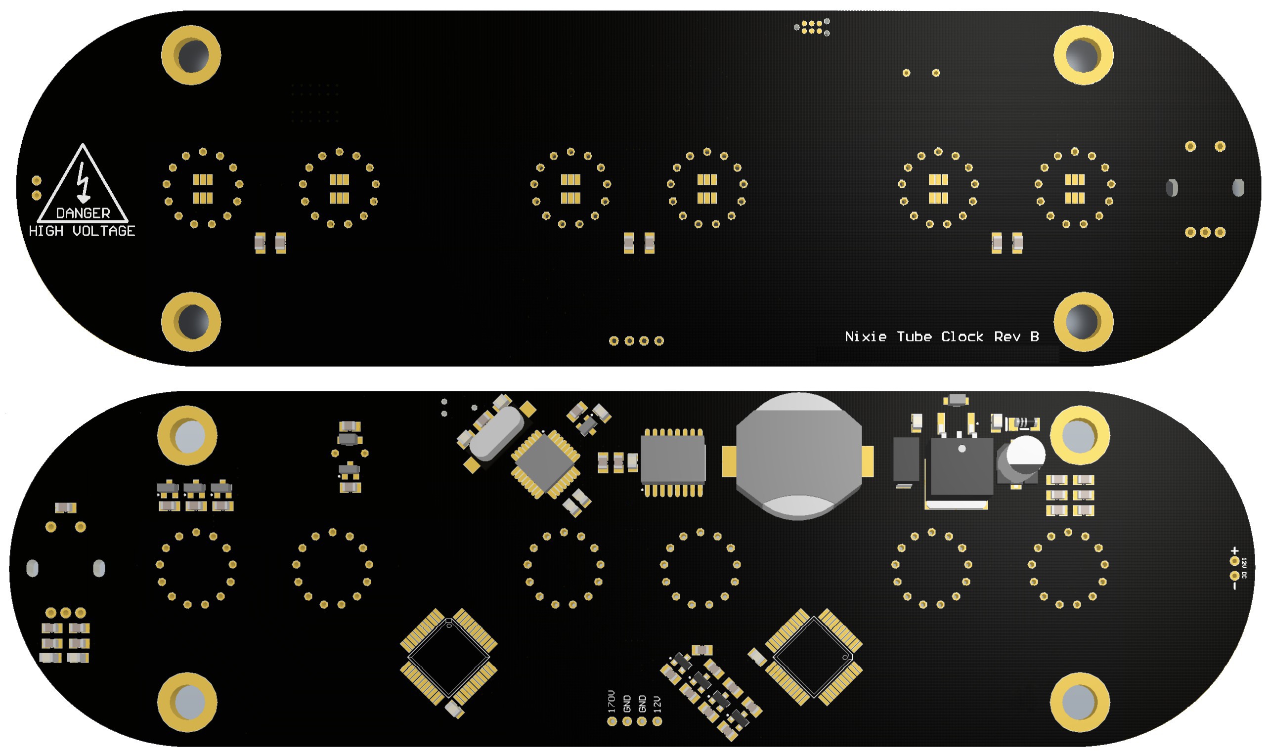
Not much to say about the PCB.
Case: 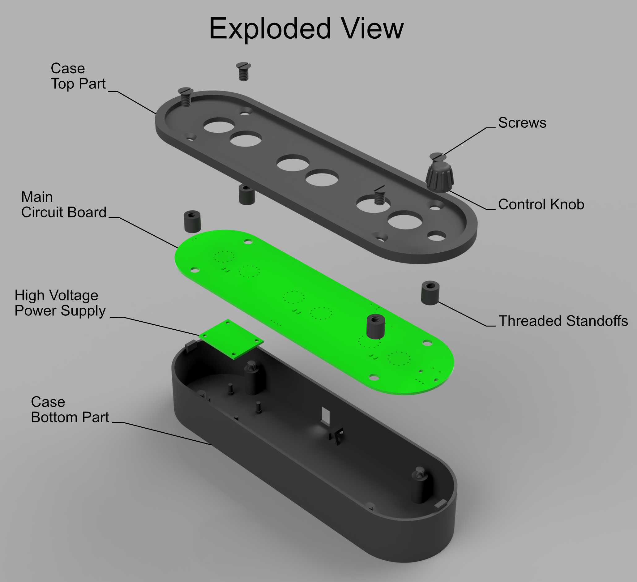 The case was designed in Fusion360 and then 3D printed in black PLA. I even printed the screws and standoffs, which worked surprisingly well!
The square hole in the bottom part is to mount an on-off switch and the hole next to it is for the cable comming from the 12V wall adapter. I also put a little support structure on the hole so I could secure the cable with a zip tie.
Future plans:
Adding features, like an alarm mode and saving the RGB settings in EEPROM.
 sjm4306
 Walter
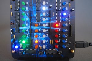
 Ian Dunn
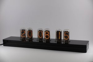
Are the STL files available for the case?