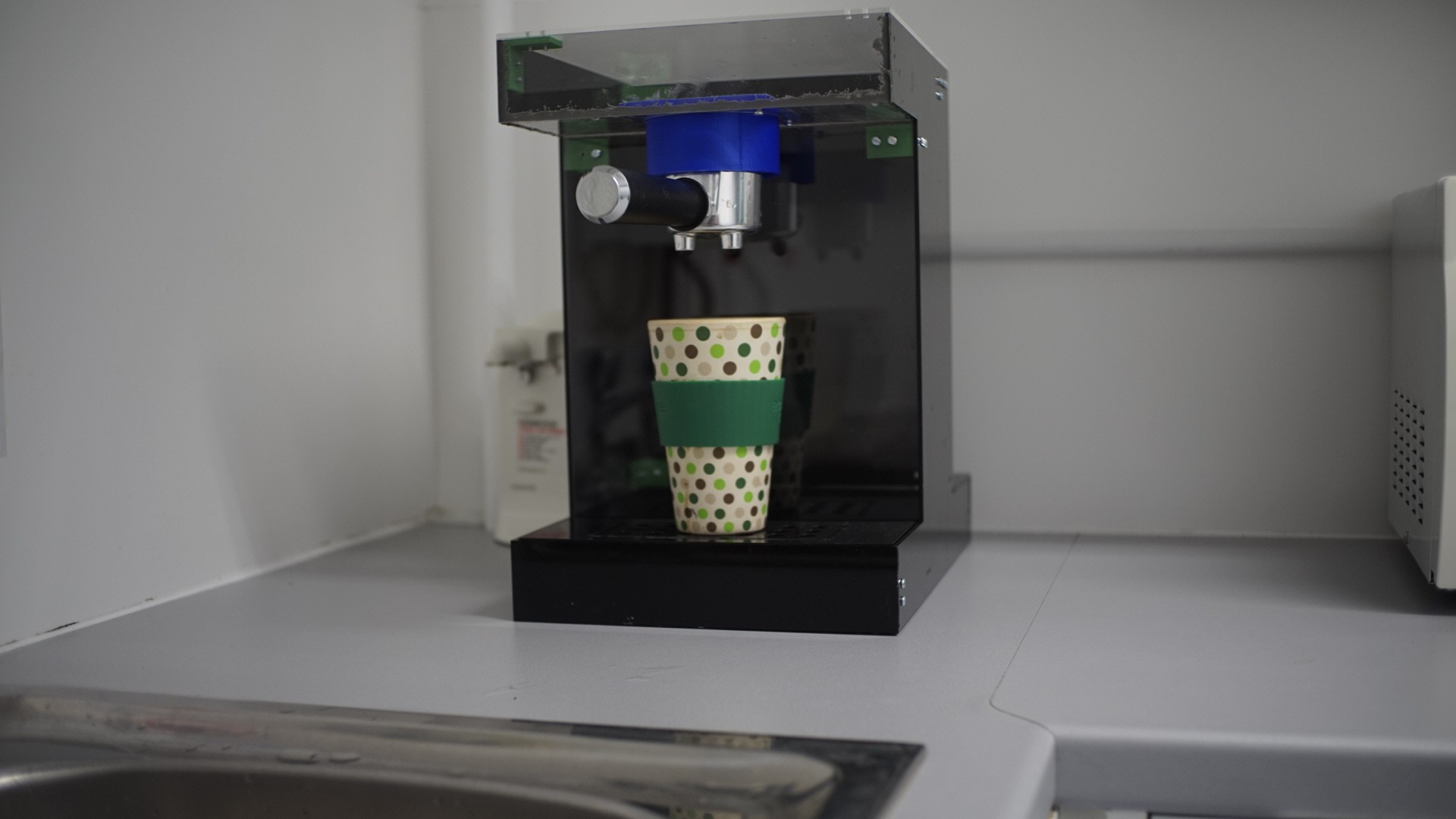
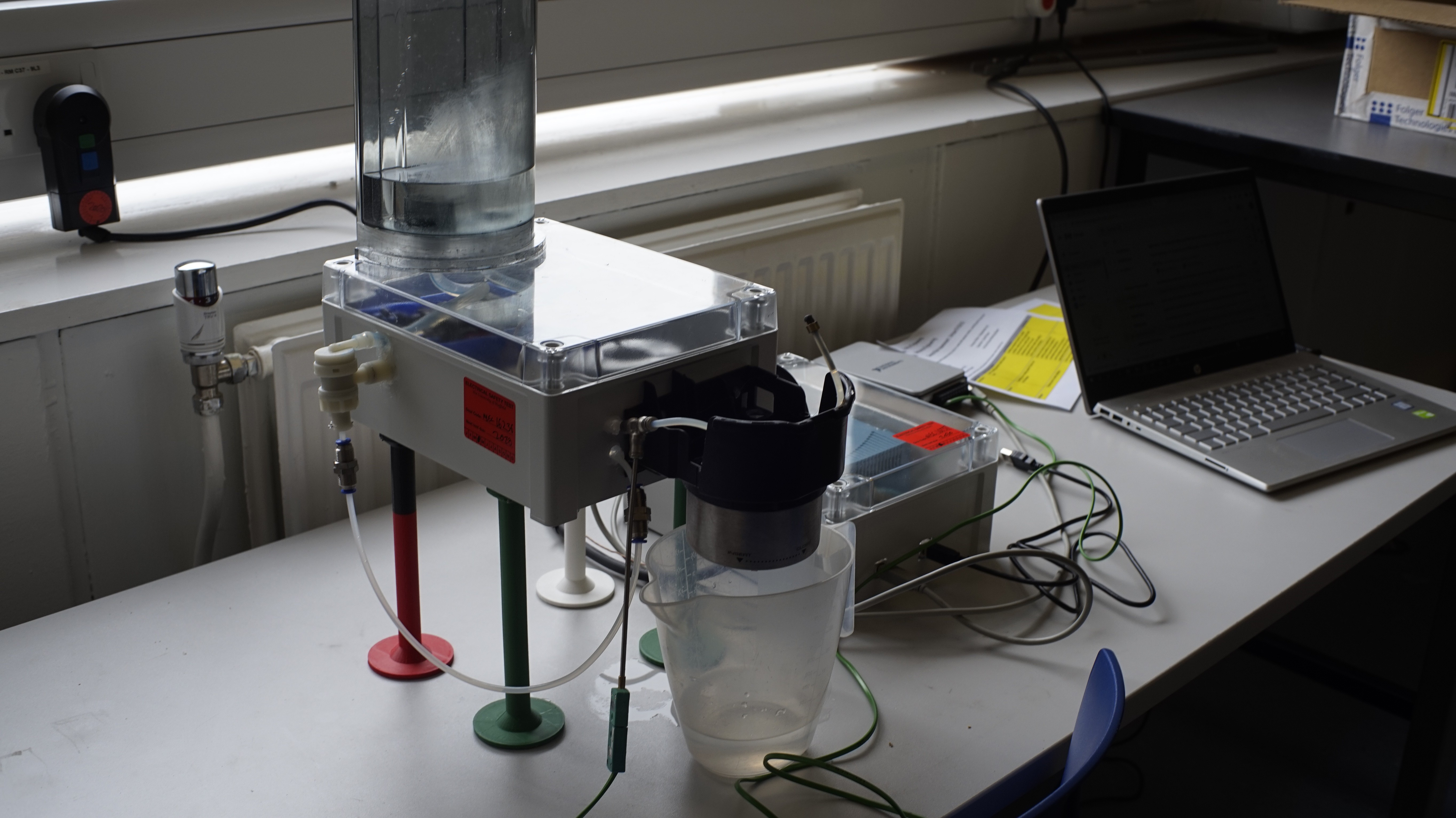
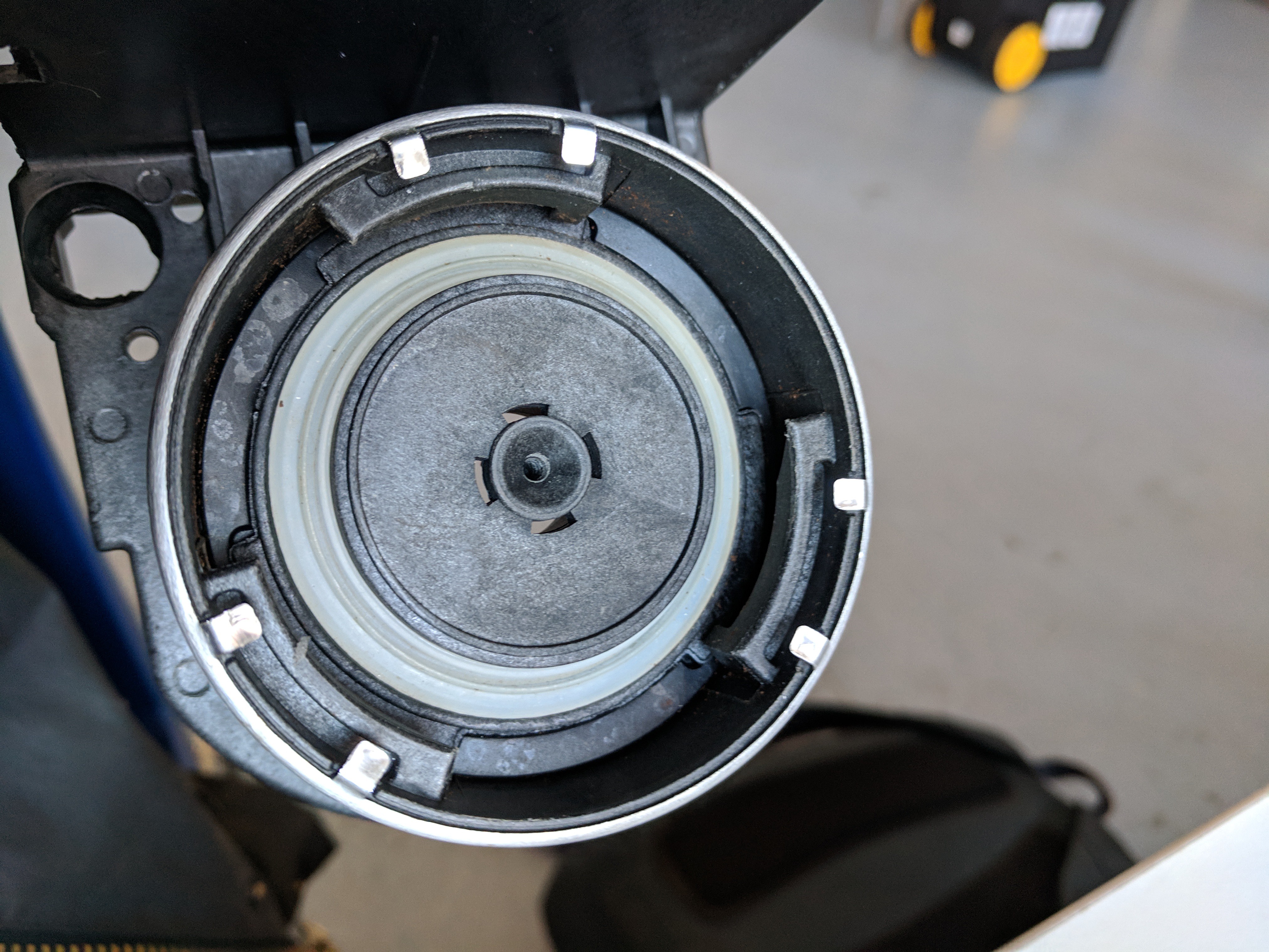
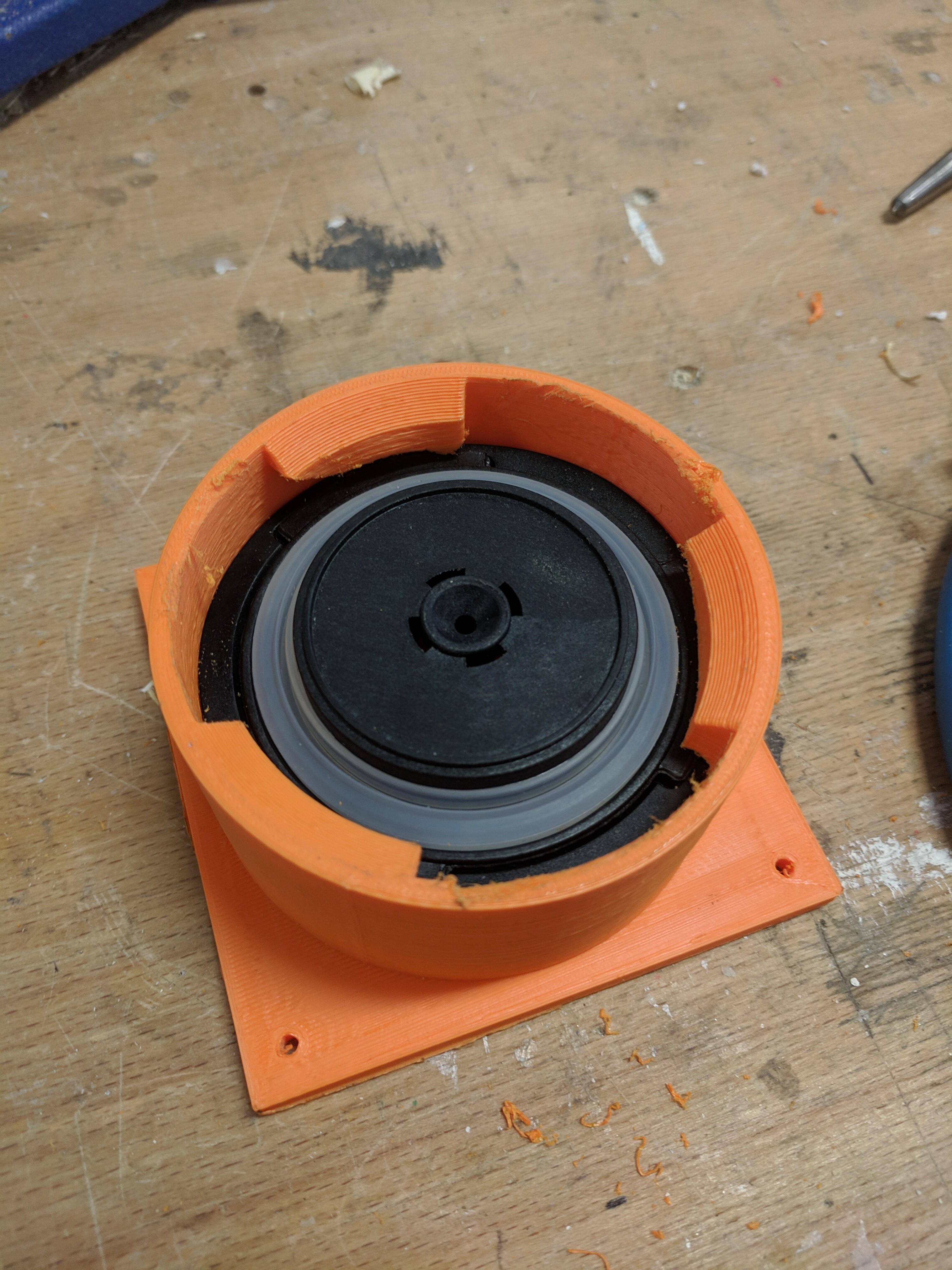
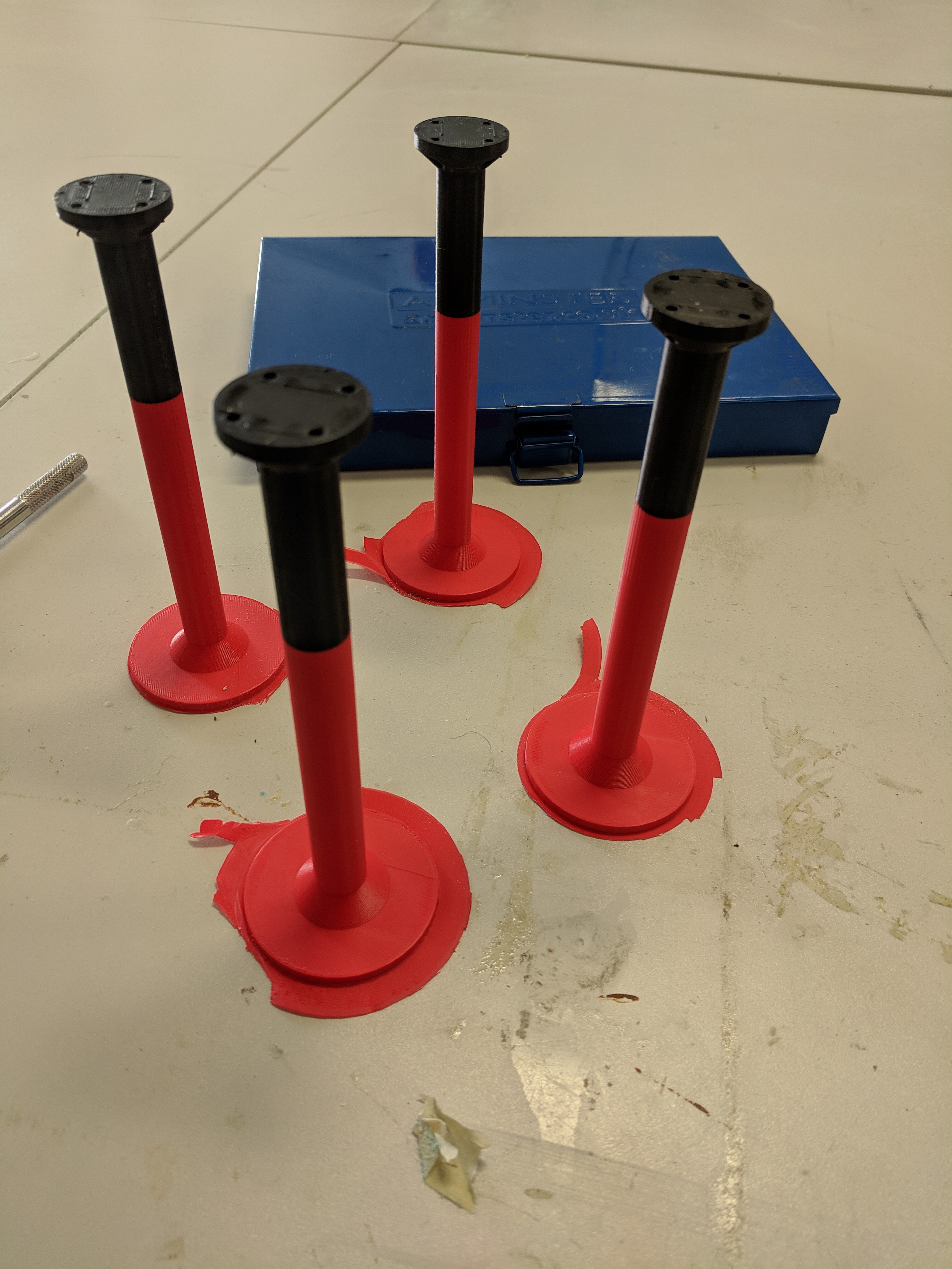
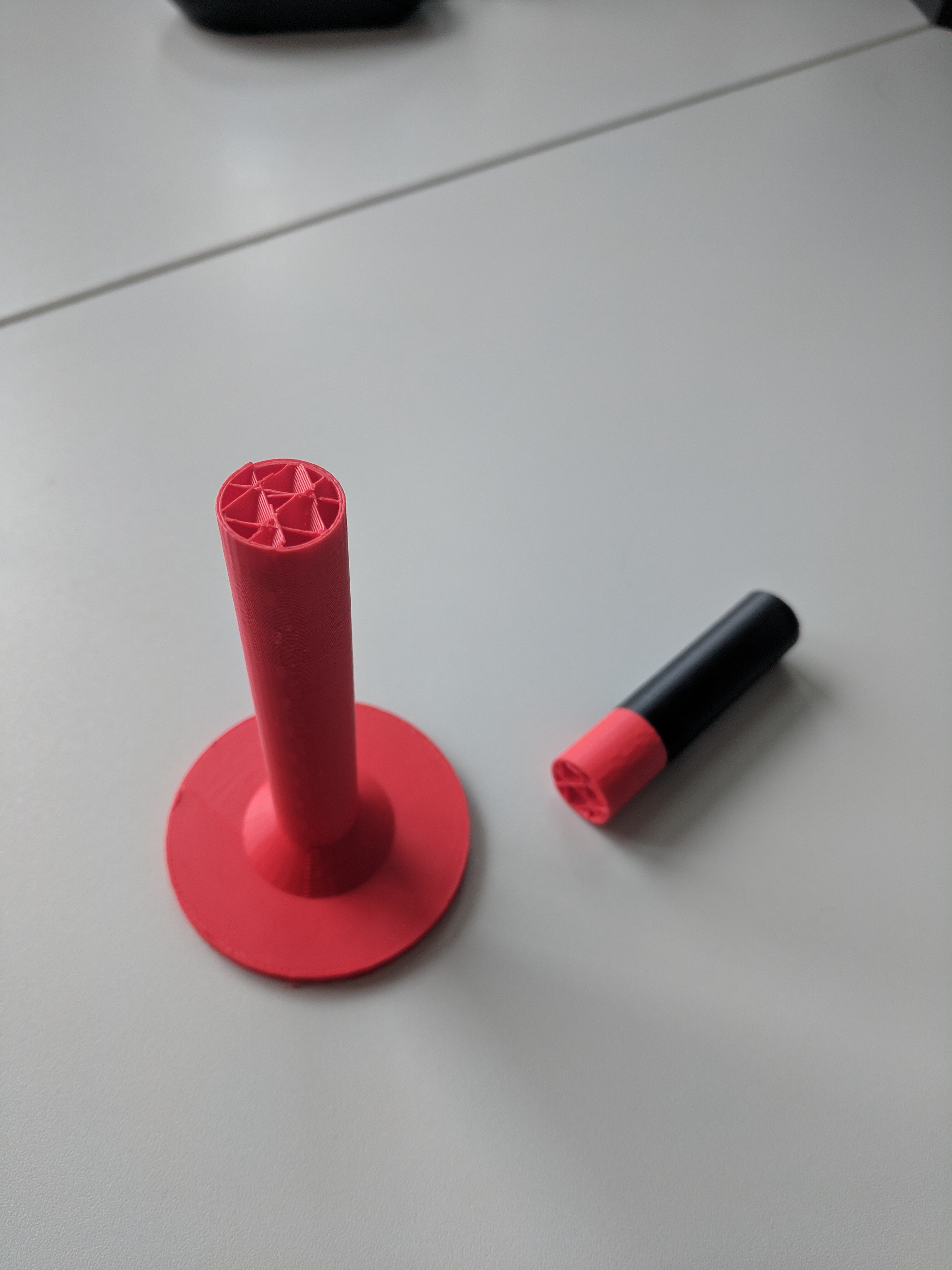
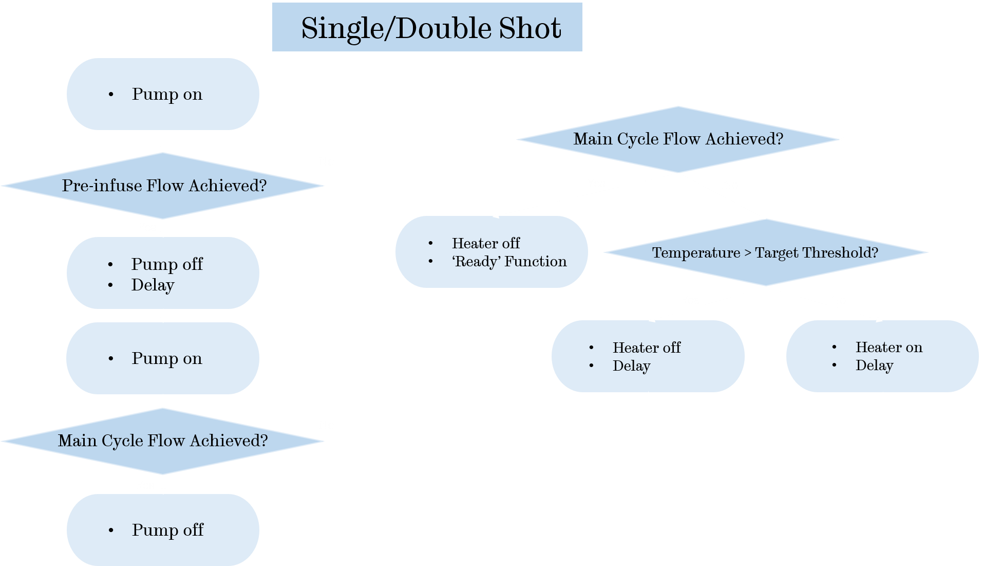
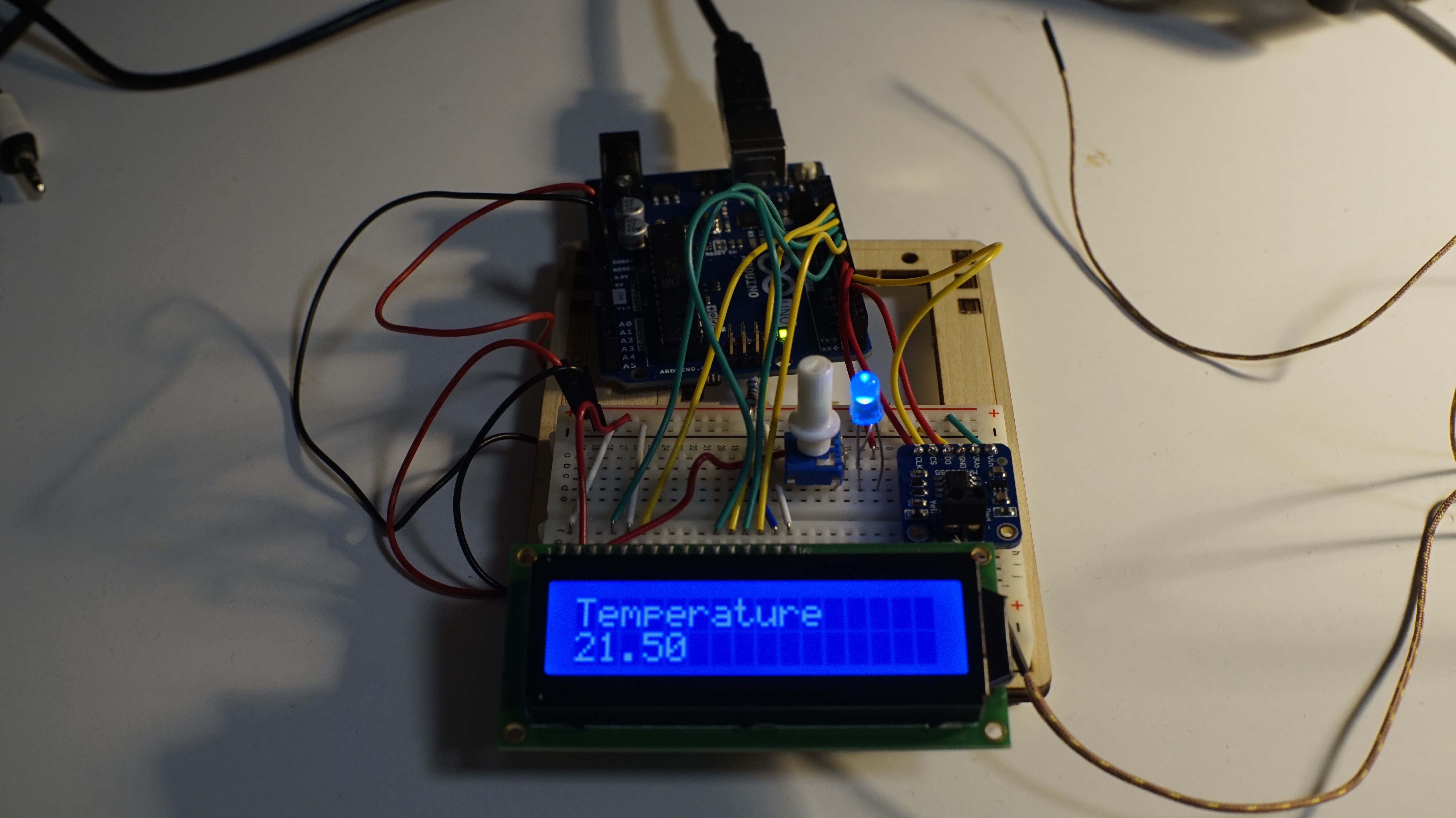
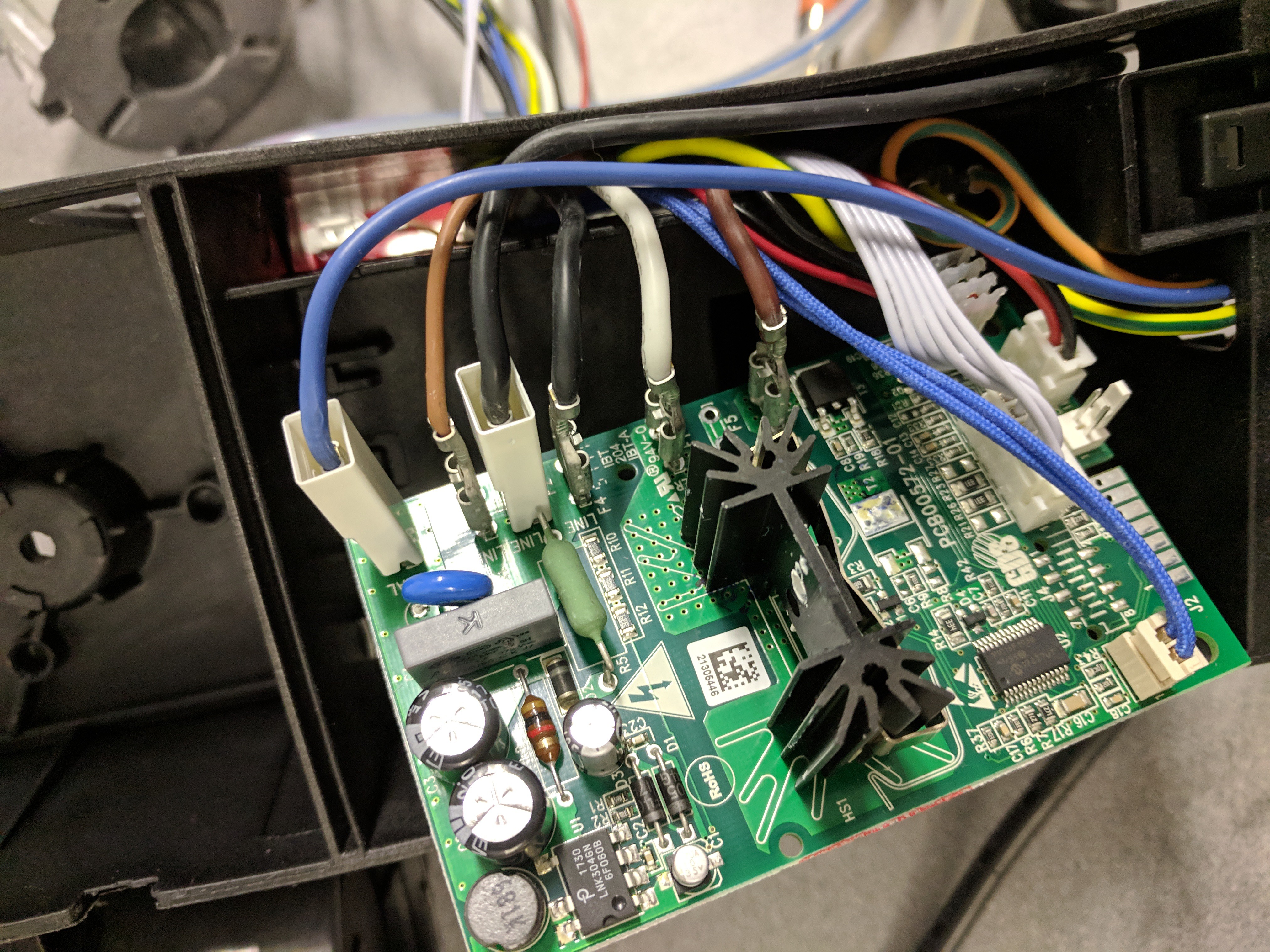
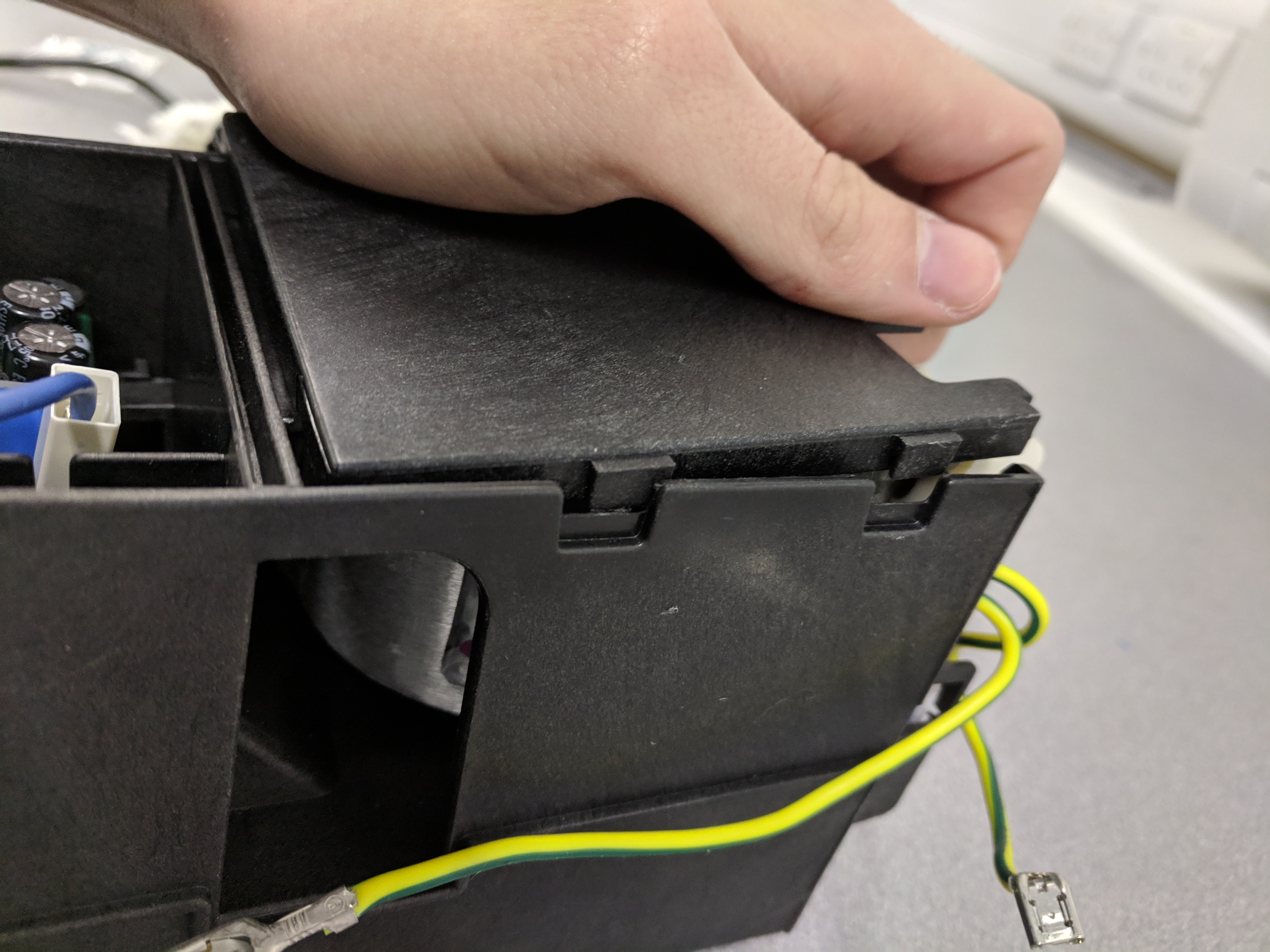
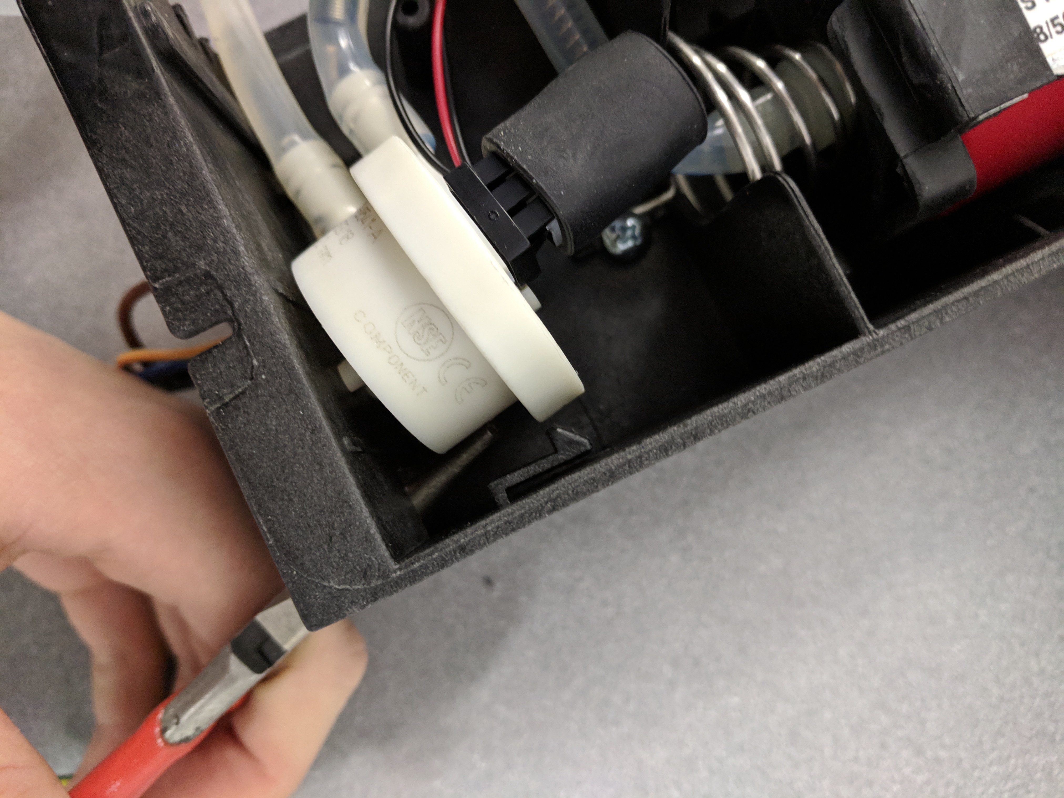
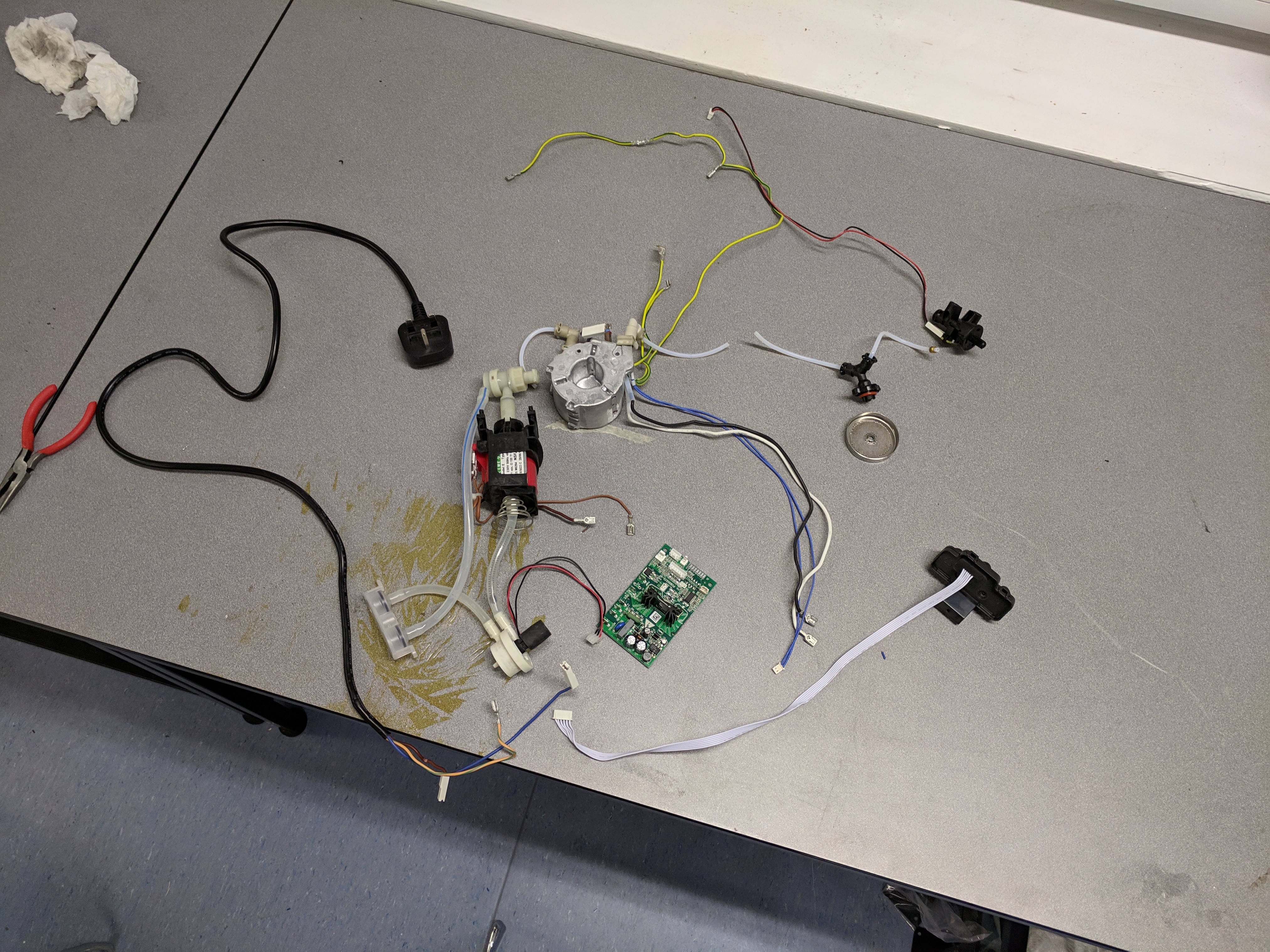
• We have coffee!!

    Zack Moss04/29/2019 at 05:37 0 comments

    I have produced a working prototype of the design, which produces pretty taste coffee! I have uploaded the files required to build it and my thesis which has details on everything, if people want more information just leave a comment and I can upload more stuff!

    First prototype design:

    Second prototype design:

  • Initial First Prototype Testing

    Zack Moss04/16/2019 at 23:32 0 comments

    As shown below the first prototype has been constructed and some basic testing has been done, but some editing to the design may need to be done due to interference the thermocouple is experiencing, suspected to be from the mains power supply.

    Code was successfully run to test the pump and heater, with both working, as shown below with the pump turning on and off in 2 second cycles.

    Over the next few days I will be documenting the temperature profile during a cycle with the machine, once the code has been perfected. So keep an eye out for the next few posts!

  • First Prototype Update!

    Zack Moss04/08/2019 at 12:14 0 comments

    Using the components from the DeLonghi Dedica Style EC685.M, a first prototype open source machine is under construction (as shown below), fitting these components into a new casing, comprising of two boxes, and replacing the control board with an Arduino. All the electrical components were placed into one box, all the water-carrying components in the other, to try and reduce the chance of electrical failure.

    Pump Housing

    Firstly, the pump was placed in a simple 3D printed housing, as shown below.

    However, this resulted in high levels of vibration. So, a new housing (shown below) was made that emulates the one in the existing machine. Results of the vibration in this new housing will be made available in the next blog post.

    Group Head

    The group head from the existing machine was sawn off and bolted onto the new machine, as it was integrated into the casing (see below). 

    For the next prototype a 3D printed group head which fits with some of the available components was made, similar to the structure in the existing machine. The first attempt fit the components but not the portafilter (See below), so the design is currently being altered.

    Legs

    Legs were 3D printed to increase the height of the machine, so that there was room for a mug under the group head. However, during installation on of the legs broke due to shearing (see below). Therefore, new legs are being printed at 90% density (rather than 30% which was default). 

    The first prototype should be finished within the next week, so expect another blog post soon with more detail on the design and results from testing!

  • Bench Testing

    Zack Moss03/15/2019 at 14:51 0 comments

    Before applying code to the espresso machine components, the methodology of the code was tested in situations that replicate what occurs in the machine itself. The flow diagram of the code is shown below.

    The pumping mechanism was replicated by using a blue LED to represent the pump, a red LED to represent machine stand-by and a potentiometer was used to imitate the flow meter.

     So, when the espresso button is pressed, the pump should turn on until the pre-infusion flow has been achieved (potentiometer turned a small amount), then delaying before pumping the main cycle until main flow is achieved (potentiometer turn a greater amount). This was successfully demonstrated below.

    To emulate the heating mechanism, my body heat was used as the “heater”, with an LED to represent power to the heater (i.e. if the light turns off, take the sensor away from my arm). 

    The target temperature was set at 30 degrees and the aim was to fluctuate the temperature about that point.

  • Proposed Code Strategy

    Zack Moss03/15/2019 at 14:15 0 comments

    One of the intentions behind the design is to replace the control board in the tested machine with Arduino control, to do this requires writing code to run the new machine. Thus, a high-level code strategy was created for the first prototype using a simple heater control method, with progression to a more advanced method (such as PID) if the temperature profile was not satisfactory.

    Firstly, when the machine turns on, it needs to pre-heat the thermoblock and maintain around a temperature close to the desired brew temperature, indicating when a shot is ready to be extracted with a “ready” light.

    The code will stay in this above loop until a desired temperature is reached. It will also stay in this loop if above a certain temperature, to prevent overheating.

    When the temperature is between these thresholds, the code will move between the “ready” and “stand-by” functions until a button is pressed, whilst fluctuating about the target brew temperature.

    Once a button is pressed, and a “mode” selected, that function will take over, with all three “modes” being similar in concept, but with different pumping timings.

    The pre-heat mode runs two double shot cycles through the machine, which aids temperature stability for the brew cycles as it pre-heats all the components in the machine, improving taste as found in the research stage.

    The brew cycles include a short pre-infusion stage, the difference between the single and double modes is simply the flow at each stage being twice as much in a double shot.

    One of the main considerations for using this code is temperature sensor placement. If the sensor is submerged in the flow between the heater and group head, it will be exposed to air temperature between cycles, which may cause malfunction and overheating. Thus, a heater surface sensor will need to be used for the start-up/ready/stand-by steps. This could be used in conjunction with a submersed sensor which is used for the brew modes, or used alone, experimenting with the sensor to find a suitable target surface temperature which returns the desired target brew temperature.

  • Temperature Stability in the De'Longhi Dedica Style EC685M

    Zack Moss12/28/2018 at 00:34 1 comment

    Introduction

    From personal use of this machine, it was found that running several cycles of hot water through the machine before pulling a shot drastically improved the taste of the espresso. Therefore, this investigation was designed to measure the variation of water temperature from cycle-to-cycle. Also, it was suspected, from the price of the machine, that it had a cheap and simple control system for regulating water temperature throughout the cycle. Thus, water temperature variation throughout a single cycle was also a variable of interest to be measured.

    Setup

    To measure the water temperature, it was decided to measure just before the water reached the grouphead as this was the most accessible location that would give a good representation of the temperature of the water hitting the coffee.

    The tube carrying the water was cut, so that a push tee fit valve could be inserted. As the tube’s outer diameter was 4mm, an equal 4mm tee valve was used (https://uk.rs-online.com/web/p/products/4454467/?grossPrice=Y&cm_mmc=UK-PLA-DS3A-_-google-_-PLA_UK_EN_Pneumatics_And_Hydraulics_And_Power_Transmission-_-Pneumatic_Adaptors_And_Fittings_And_Couplings-_-PRODUCT_GROUP&matchtype=&pla-190320696483&s_kwcid=AL!7457!3!88057055403!!!g!190320696483!&gclid=EAIaIQobChMIpdTElffR3gIVxrTtCh2-mgg-EAQYBSABEgJZgfD_BwE&gclsrc=aw.ds). This tee valve was chosen as it could handle the pressures and temperatures of the operating conditions.

    To measure temperature, a sensor was used, which contained a k-type thermocouple. As the sensor diameter was too small for the tee valve, Araldite was used to glue the sensor into the valve and fill any space. The tip of the sensor was placed into the path that the water would take, whilst ensuring that the tip nor the glue blocked this path (show schematic and image of it completed).

    A hole was then cut into the side of the machine so that the sensor could poke out, where it was hooked up to a DAQ (cDAQ-9171), which was plugged into a laptop. The instructions to setup the sensor to LabVIEW were found here.

    Experiments

    Experiment one

    Firstly, the machine was run from cold, allowing approximately 30s between cycles (roughly the time to change the portafilter), running double shots each time.

    Experiment two

    Next, the machine was run with each cycle back-to-back, from cold, running the next cycle as soon as possible.

    Experiment three

    Then, once again cycles were ran with 30s between each, but after preheating the machine with two back-to-back cycles.

    Whilst conducting these experiments, some other variables were measured, such as volume flow rate and the time that the pump was running.

    Results

    Experiment one

    The first graph shows the sensor run at cold conditions, to demonstrate the natural temperature variation. The following nine graphs show the nine runs ran sequentially.

    The data shows that the temperature stability does not seem to vary much from cycle to cycle. However, it is noticeable that the temperature is not stable during a cycle, the temperature consistently rises until it reaches a peak and then drops. Also, the temperature begins to drop before the pump stops running. This sort of temperature distribution suggests that the heater is simply being turned on for a set amount of time, or until it reaches a certain temperature, before turning off.

    Red dashed lines indicated the pre-infusion pumping cycle, green dashed lines indicate the main pumping cycle.

    Experiment two

    This experiment shows that when cycles were ran back-to-back, the same cycle temperature instability was present. However, much higher peak temperatures were reached. This would suggest that it is not simply a maximum temperature that causes the heater to turn off, else the maximum temperature would not vary the amount it did between experiments one and two.

    Experiment three

    This experiment shows...

    Read more »

  • Dismantling a De'Longhi Dedica Style EC685M

    Zack Moss12/27/2018 at 17:29 1 comment

    Tools needed:

    Phillips head screwdrivers (PH0 & PH2)

    Security torx screwdriver (T20)

    Flathead screwdriver

    Sharp knife (to cut any cable ties)

    Firstly, remove the water tank from the machine. Then unscrew the screws on the back. There is 2 panel strips that need to be removed, with the help of the flathead screwdriver as leverage (see image below).

    Next, the metal clips must be undone by using the flathead screwdriver to prise them open. The metal casing can then simply pulled off (This may require a reasonable amount of force).

    The top of the machine has a sliding lock mechanism. To open it, first pull the top up, this may require some force the first time it is done. Then slide the top back, being careful as there are wires attached between the main body and the top.

    At this point, the machine was then experimented on to measure water temperature throughout the cycle, details of that can be found here.

    After experimentation, full dismantling was continued. The top was taken off again and the sensor equipment removed. Using the same Phillips screwdriver, all the visible screws on the top interior of the machine were removed, along with any components. 

    The water tubes had two types of fixture. The thinner tubes had a U-shaped clip which is simply pulled out (easier by using something like a small screwdriver to pull it out). 

    The larger tubes had a more rigid fixture, they are removed using pliers to clasp the two ends together, and then pulling the fixture along the tube away from the fixture point (see image below).

    Once all these screws and fixtures have been removed, the following components can be taken out: grouphead; grouphead valve; steamer control switch; main button control panel. The main button control panel requires a PH0 screwdriver.

    As can be seen inside the machine, there is an internal tower which contains the main components. To remove this tower, the bottom of the machine needs to be opened and all the screws removed, requiring the PH2 and a T20 security Torx screwdriver.

    Ensuring any earth cables have been unclipped, the tower can be pulled out. 

    Next, make a note of cable positions on the control board, before unclipping them.

    Removing the heating element is the most difficult step as it very tough to remove the outer panel (or I was doing it wrong). It consists of 4 plastic clips, however they didn’t seem to unclip easily at all. I ended up using pliers to pull it off, after a lot of effort (please comment if there is an easier way to remove this panel). Once the panel is removed simply unscrew the heater from the tower.

    The pump is easiest removed by leveraging it out of the clip (as shown below). Then once all screws are removed it should pull out easily.

    Everything can then be removed from the tower. Details of the components are shown below.