 Eric Hertz
We now have Incandescent DRAM and a refresh controller!
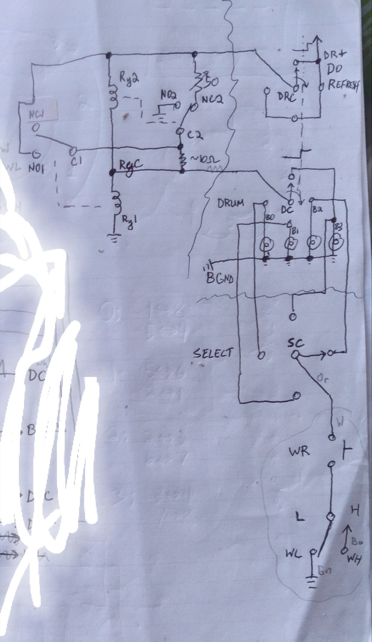
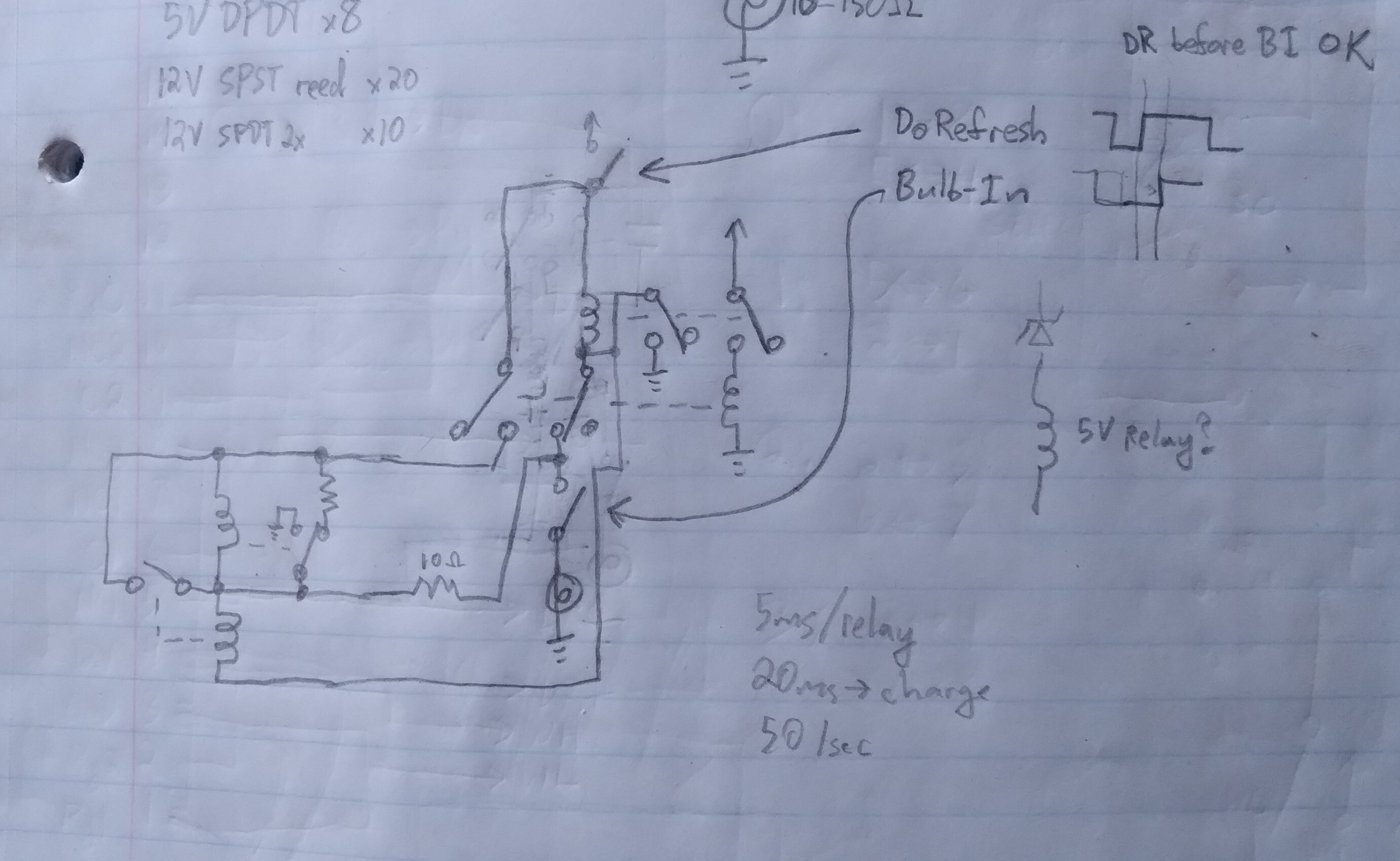
(Note, I have since moved the 10ohm resistor such that RyC is now connected directly to C1 and C2. This resistor allows writing at any time, regardless of the refresh circuit's being plausibly already latched at the opposite value. In the schematic, as drawn, it allows a little bit of current to flow through the bulb, heating it up, even when Relay2 has latched low. Moving it as I described prevents any current from flowing through the bulb after Relay2 latches. The drawback is that if the relays are already latched when a write comes through, it will not automatically unlatch them, and instead just waste power through the resistor until the refresh circuit moves on to the next bulb. Still, beter than warming a cold bulb!).
Do-Refresh resets the latches in the refresh circuit (shown in the last post) when the "drum" rotates between two bulbs.
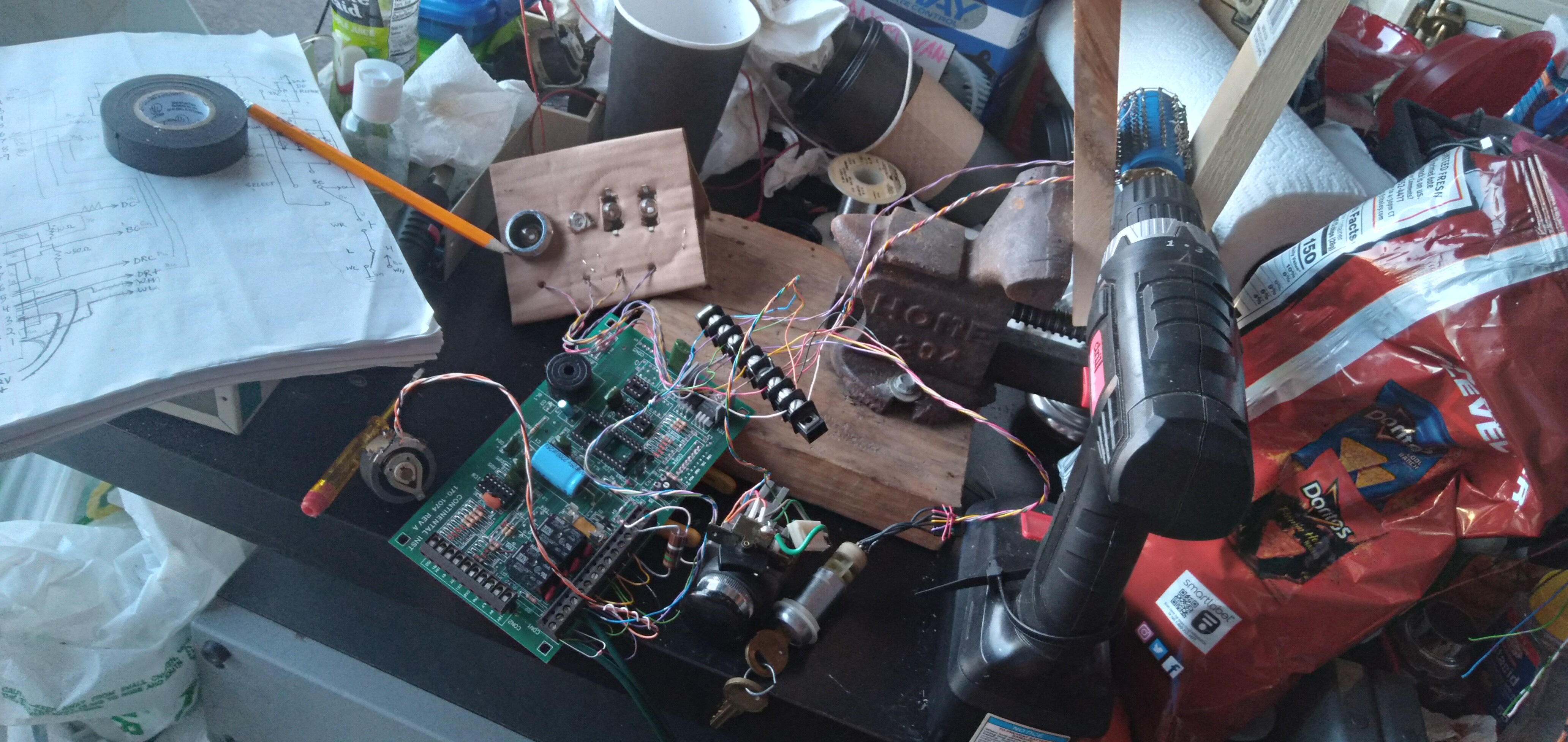
The "drum" is a rotary switch removed from an old 6-way Parallel-Printer switchbox, and modified slightly to remove the detents as well as the endstops. Also, it handled 2 poles of six positions each on each "disk", but was easily modified to handle 1 pole of 12 positions, by removing one of the two sets of brushes, and tying the poles together.
I had four identical bulbs to work with, so each is handled by three of the 12 positions. The Do-Refresh signal is handled on another rotary-switch disk, tying all its positions together to generate a reset pulse when switching to the next position. So each bulb gets refreshed three times before it moves to the next. I did it this way, rather than doing all four in sequence three times, because I was unsure about the timing... e.g. whether Do-Refresh might hold the previous bulb's value onto the next, due to the layout of the switch wipers. Three refreshes in series would help assure that even if it held the previous bulb's value onto the next, it would have two more tries to switch over to the current bulb's value. It also means all the relays are switching three times as often as they need to. Heh! It's really quite amazing how fast these things are!
Do-Refresh is questionable, to say the least; if it occurs *before* the bulb is switched-in, it'll think the bulb is hot, so latch (and write) it high, even if it was low (cold). I tried adjusting the wiper a bit so it'd be later in the rotation, but it wasn't really assurable, and also meant that it might be more prone to holding the previous bulb's value onto the next, so eventually I scrapped the wiper-adjustment and gave it a go with the normal wiper arrangement...
Basically, I'm saying this was thrown together not expecting the timings to be accurate-enough to actually function... but it does, surprisingly well, considering!
So, the circuit allows for writing any bulb asynchronously to the refresh circuit; a Write overrides the refresh.
The only "cheat" in here, as far as to its being implementable in the era of the telegraph, is that I added flyback diodes on the relay coils, which, really, was just a quick test that may not really have been necessary.
Calibration is finicky, but not impossible with a rheostat. And, I think if I had the timings better-aligned (make contact with the bulb first, then Do-Refresh, then maybe even break Do-Refresh before switching out the bulb) it'd be far more reliable.
(Note that since these bulbs retain their heat for so long, it's actually a bit less finicky than I'd expected. Earlier simulations suggested that the appropriate resistor value was highly dependent on the refresh rate and duration, nevermind the coil resistances, and more. But in the video you can see its working despite the slowing of my drum rotation, etc.)
If I was making a drum, maybe with magnets and reed switches, or even bumps and microswitches, assuring proper timings would probably be quite doable.
But, I've come up with a circuit, adding two DPDT relays, that should delay switching-in the Refresh circuit until after the bulb is *detected,*... I think it'd do, but I have to wait on some relays. And, as far as an actual system based on this crazy idea, it'd mean four (instead of two) relays per "column" (of, I imagine 8 bulbs is feasible per column).
I'm not doing anything fancy, like refreshing with overvoltage pulses, I'm willing to bet it not only feasible, but also capable of bumping it up to 16 bulbs per column. And, these bulbs are big, as are the relays... not at all ideal for speed, power, etc. Not really even well-suited for working together (e.g. coil resistance vs. bulb resistance). Which, again, suggests this system could be *very much* improved with the right parts. Kinda surprising it works at all, given the random parts I had on hand!
I also think it interesting that it measures the bulb as "hot" *long* after it stops being visibly hot. In designing this, I guess I'd imagined the resistance to be very non-linear with temperature, and instead more related to its becoming "red hot." I guess it's crazy now that I think about it, but I guess I kinda thought of the metal in the filament as becoming molten. Hah!
No, the "hot" vs. "cold" resistances are measurably different nearly a second after the glow disappears. And not just measurable to a multimeter, but measurable-enough to dramatically change the output voltage of a somewhat heavily-loaded voltage-divider... to switch relay coils! I think that pretty interesting.
There's also an interesting "intermediate state" that I noticed (and actually planned to make use of) in my simulations... Here, I didn't expect to actually *see* it. In fact, the two-relay refresh-circuit was designed to hopefully *reduce* the range of the inbetween-state. If the bulb resistance is in a certain "invalid" range, this circuit causes it to eventually register as "high". But it takes several refresh cycles to get there. In one of my earliest refresh-circuit designs, it only used one relay. The result was, of course, only one of two states possible, but the threshold might vary more with, say, ambient temperature. And, I dunno about real relays, but those in the simulation could actually get stuck between the normally-open and normally-closed states. At the very least, in the real-world, it might mean it would take longer to switch between contacts... The result, then, being that bits that were only barely-registerable as hot would get *less* time to reheat than those that really didn't even need the extra heating. Heh. So, that's why I changed to the two-relay design, which should speed things up dramatically, as well as giving much better defined high and low threshold values.
With a properly-timed system, that intermediate range would never be the case. But it's visible in these vids because, well, timing is pretty hokey in this prototype. But, it's actually nice to see it working to turn those seemingly undefined states into a defined state. Data-recovery, or something.
Earlier, more-finicky experiment:
Discussions
Become a Hackaday.io Member
Create an account to leave a comment. Already have an account? Log In.