 Jan
JanLast update to this log: 13.12.2018
Added link to a small USB UART adapter by @Jan--Henrik
What's this chip, the CH330N?
It offers USB to UART function and allows to connect your microcontrollers "directly" to USB for programming and communication with your PC or phone.
Features
- USB to UART communication
What are the available footprints?
It does come in a standard SOP-8 case. Pin spacing is 1.27mm. Dimensions (Lx Wx H measured) of the real part are: 4.9x 6.1x 1.6mm
Pinout
Pin functions are as follow:
| Pin | Name | Function | I/O |
|---|---|---|---|
| 1 | UD+ | USB Data + (USB cable color white) | I/O |
| 2 | UD- | USB Data - (USB cable color green) | I/O |
| 3 | GND | Ground | - |
| 4 | RTS# | request to send | O |
| 5 | VCC | positive power supply (3.3 or 5V) | I |
| 6 | TXD | Data out from the chip | O |
| 7 | RXD | Data into the chip | I |
| 8 | V3 | - If VCC is 5V, there's 3.3V out on this pin. - If VCC is 3.3V, you need to connect it to VCC and decouple it with 100n to GND. See below for details! | I (O?) |
The "mysterious" pin V3
There's been debate on what this pin does. I did test it with the following configurations.
VCC = Vusb = 5.05V
Both USB data cables are connected. Here's what I found out, when V3 is
- left floating: V3 measures 3.222V in this configuration.
- decoupled with 100n to GND: 3.225V
- connected to VCC (3.3V): to be found out (might short it out, tested later)
- connected to 5V: to be found out (might short it out, tested later)
Idle power consumption in this configuration is 5.61mA when pin V3 is decoupled with 100n to GND. When left floating, power consumption is 5.58mA.
At VCC = 3.3V idle current consumption with USB data cables connected is 3.65mA.
When USB data+ and data- are not connected, the chip draws 0.09mA. RxD measures 5.05V (= VCC), TxD is the same. This is consistent with the datasheet. At 3.3V the idle current consumption without USB data lines connected is: 0.014mA.
VCC = 3.3V
- left floating: to be found out
- decoupled with 100n to GND: to be found out
- connected to VCC (3.3V): to be found out
- connected to 5V: to be found out (might short it out, tested later)
Current delivering capability of pin V3
For the following tables I used resistors to simulate a current-draw from pin V3 to GND. The current is the total current (0.09mA IDLE + I_V3)
VCC = 5V
Left open, the voltage is 3.22V.
| Resistor V3_to_GND (R) | I_total (mA) | V_V3 (V) |
| 180 (5%) | 18.06 | 3.205 |
| 150 (1%) | 21.57 | 3.203 |
| 120 (5%) | 27.31 | 3.201 |
| 100 (1%) | 32.05 | 3.200 |
| 62 (1%) | 51.8 | 3.190 |
| 33 (1%) | 88.8 | 2.900 |
| 24 (5%) | 103 | 2.430 |
VCC = 3.3V
When VCC is 3.3V you can not draw much current from this pin. The datasheets advises to connect V3 to VCC in this configuration. I think the chip doesn't bypass the internal voltage source but the voltage offset is too small to deliver any serious current. I did a few tests anyway:
| Resistor V3_to_GND (R) | I_total (mA) | V_V3 (V) |
| 390 (5%) | 8.234 | 3.140 |
| 330 (5%) | 5.572 | 3.106 |
| 200 (5%) | 15.081 | 2.960 |
| 150 (1%) | 19.17 | 2.844 |
Conclusion
The tables above shows what you could expect to draw from the internal 3.3V source when powering the chip off of 5V. A safety-rule would be to not draw more than 50mA from it, as the voltage drops quite a bit going much higher than that. Powering the chip off of 3.3V, you're expected to connect V3 to VCC.
Sample circuits
The following circuits have been tested by me. They do work. Details under the corresponding headline.
Standard (datasheet) circuit
The standard circuit is as follows:
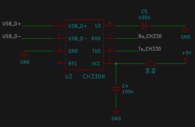
It is pretty basic and features no protection whatsoever. Rx and Tx are on a 5V level here, as the CH330 is powered with 5V! So do not use this circuit, if your micro's Rx/Tx are not 5V-tolerant!
VCC = 3.3V, USB-power not connected
Here it gets interesting. I just pushed the datasheets and rules of good design aside and tried the following:
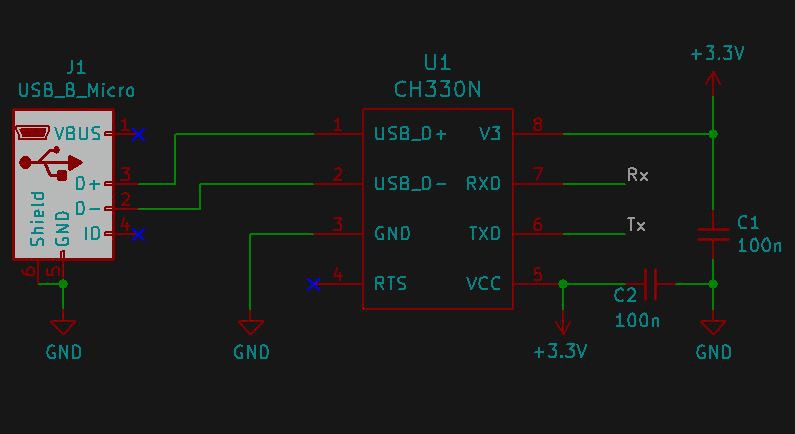
The chip is powered by external 3.3V while the 5V from the USB is not connected. I just connected GND and D+/D-. Voltage levels at Rx and Dx of the CH330N are 3.3V then. Data transfer from the CH330n to an FTDI 232RL does work at 256000BAUD with no problems.
Programming an Arduino Pro Mini 3.3V, 8Mhz
The RTS pin is pulled down by the Arduino IDE, when data transfer starts. This signal needs to pull the reset of the Atmega328P down. The Arduino Pro Mini boards have a DTR connection, which serves the same purpose.
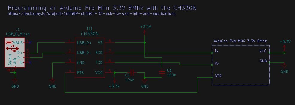
Uploading programs is as easy as using an clone Arduino Micro which usually come with an CH340G.
Power consumption and sleep modes
In this section I'll go into detail on how much current the chip draws in each state. This will include the two voltage levels of 5V/3.3V, if the USB data lines are connected etc.
First, we'll look into the details when powering the chip off of 5V:
FAQ
- Does it have a power save mode?
- Doesn't seem like it. The bigger brothers like the CH340x have a sleep mode and their datasheet has its current consumption listed as I_slp. There's nothing similar in the CH330N datasheet.
- Idle current consumption is around 5 to 6mA with USB data lines connected
- Idle current consumption without USB data lines goes down to 0.09mA at 5V VCC
- Idle current consumption without USB data lines goes down to 0.014mA at 3.3V VCC
- Can I implement some power saving myself? Can it be turned off safely?
- to be found out
- Does it need an external clock source, quartz, crystal oscillator?
- No, it has one integrated
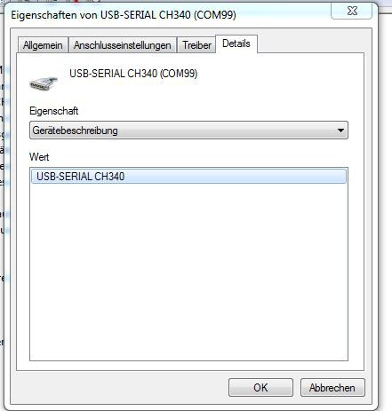
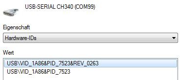
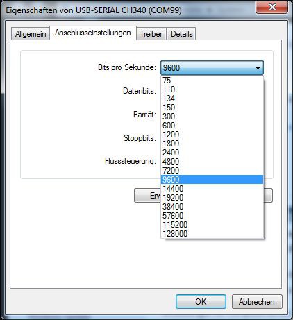
- Which BAUD-rates are supported? How do you chose a transfer rate?
- it is recognized as a CH340 in Windows. If you have installed the CH340 driver before (I did and chose port COM99 for my Arduino clones), you plug it in and are ready to go:
![]()
![]()
![]()
- What's the maximum transfer rate?
- I've done a test on that, see my video here
Articles / further reading
- This article on hackaday.com
- especially look for comments from user "Icenowy Zheng", he seems to have some knowledge about WCH devices in general
- Here you can find a small USB to UART breakout board by user @Jan--Henrik