SHAOS
SHAOSWhy did I start this? It's obvious - people need simple and inexpensive RISC-V computer to play with to know new RISC generation better - it's a future anyway :)
Project was started on November 18, 2018 when I played with very compact emulator of RV32I[MA] that @Frank Buss shared in Hackaday FPGA chat:
https://gist.github.com/FrankBuss/c974e59826d33e21d7cad54491ab50e8
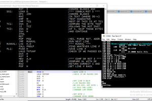
it's based on RISC-V emulator from Fabrice Bellard ( https://bellard.org/tinyemu/ ) but supports only RV32I subsystem (with optional RV32M and RV32A subsystems) and turned into single text file with 1.5 thousand lines of C code. It's even able to pass all 55 compliance tests for RV32I and run Zephyr RTOS examples! So I started from this little emulator with the same MIT-license and converted it to pure C:
https://gitlab.com/nedopc/npc5
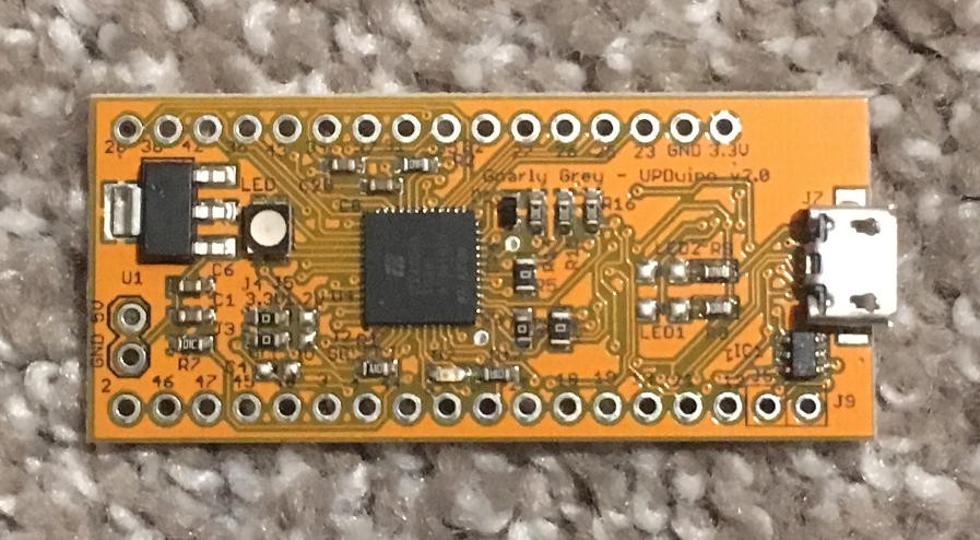
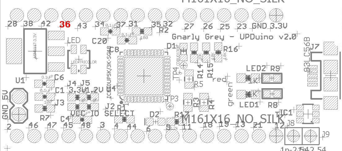
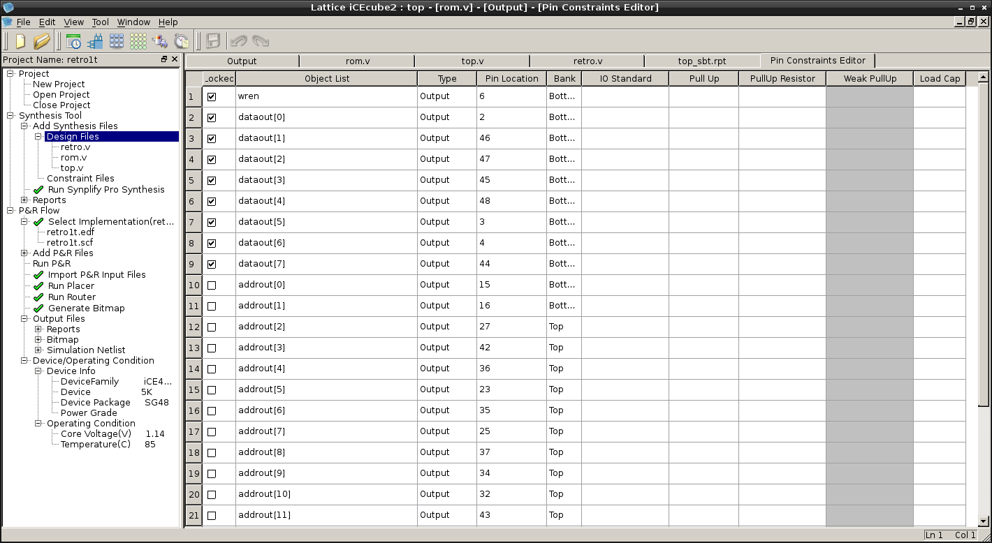
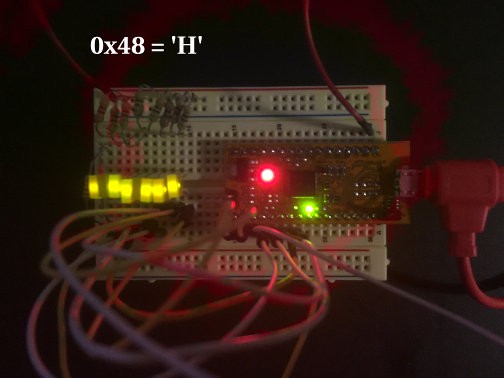
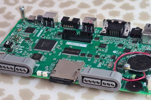
Then I wrote my own Verilog implementation of RV32I for UPDuino v2.0 board with iCE40UP5K FPGA:
Documentation has some mistakes, so I fix them as I find them:
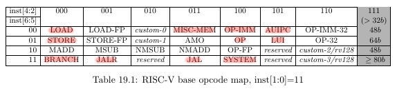
RV32I subset is only 1 page of instructions (captured from official spec):
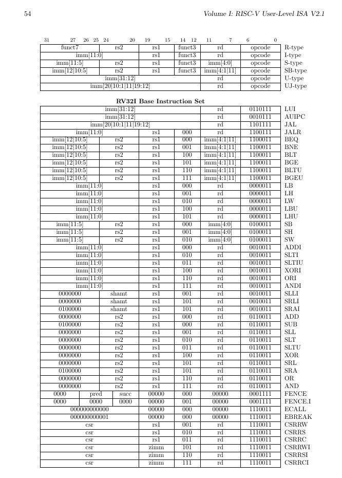
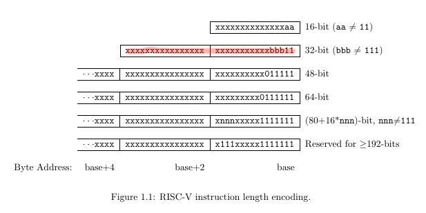
As you can see opcode is in 7 lowest bits - as we can see bits 1 and 0 are always 1s because of interesting approach to instruction set extension:
Also they have divided instructions to families this way (highlighted what was used for RV32I):
 UPDATE: Article on Hackaday: https://hackaday.com/2019/11/19/emulating-risc-v-on-an-fpga/
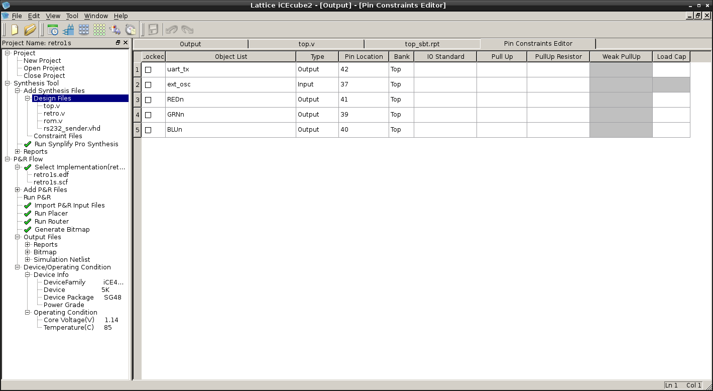
 Jara
Jara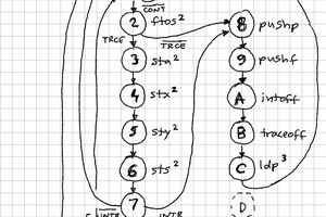
 zpekic
 Tim Ryan