Close
0%
0%

2 Transistor 4 state FlipFlop

This circuit with 2 transistors, 4 LEDs and a few resistors has four stable states !

Similar projects worth following
This circuit can store 2 bits with only 2 transistors. The 4 LED's indicate the state. The circuit was first simulated with the Falstad simulator. After that, a working version was built.

The Falstad simulation of the circuit is available in the files section. In the File menu of the Falstad simulator, select "Import from text" and paste the contents of the file in the files section.

As you can see, there are only two transistors, T1 and T2.

The upper part of the screenshot has the two collector-resistors (220 Ohms), and the 330 Ohm and 10K resistors that you see there are only for putting the circuit in one of the four states with the four pushbuttons S1 up to S4 (but the circuits with 10K and 330 have some influence on the amplification of the circuit so they can not be left out).

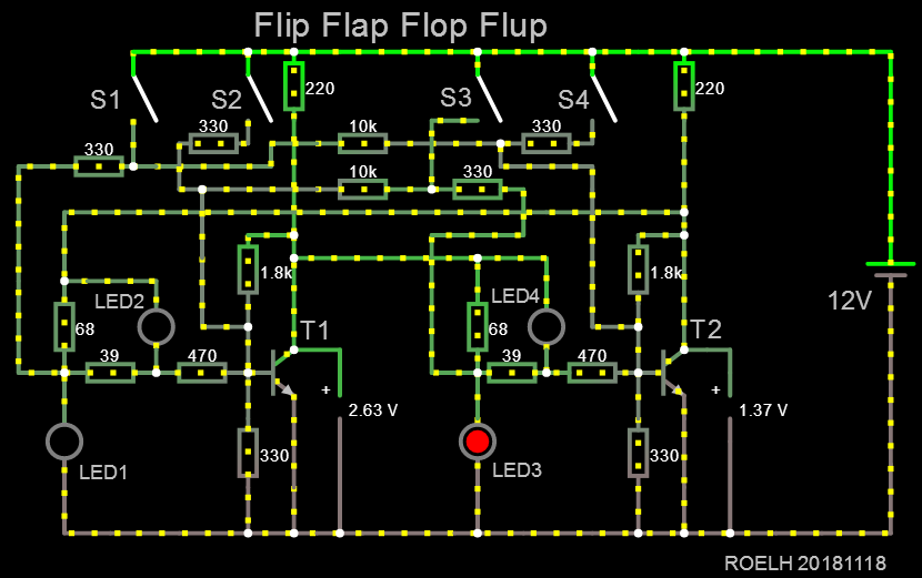
The simulator also shows you the collector voltage of both transistors (T1: 2.63V, T2: 1.37). 

This table shows some facts of the circuit:

StateSwitchLED1LED2LED3LED4
1S1ON
2S2ONON
3S3ON
4S4ONON

low_power_ffff.txt

Falstad simulation file for the low power version

plain - 3.58 kB - 11/21/2018 at 21:31

Download

falstad-flipflapflopflup.txt

This is the file for the simulation

plain - 3.50 kB - 11/20/2018 at 21:33

Download

  • Real hardware

    roelh01/20/2019 at 08:53 1 comment

    Yesterday I did build the circuit (low power version). It actually worked the first time.

    I did not use pushbuttons: instead of the S1 and S3 button, I simply touched the 15K - 2K2 connection with a wire to 5 volts, and instead of S2 and S4 I used a temporary wire to connect the low side of LED2 or LED4 to ground. So the 3K3 resistors connected to S2 and S4 were also not used.

    The LEDs that I used did not respond well to the 0.5mA that th circuit provides. Raising supply voltage to 6 volt brought some more light (at 6 volt the circuit also worked well).

  • Low power version

    roelh11/21/2018 at 21:25 0 comments

    In the comments @matseng  said that he wants to build a memory system that also heats his room with 3000 Watt. Problem is, that the first design generates 1.1 Watt for 2 bits storage. So he can only store 5454 bits (680 bytes).

    I made a new version for him, that uses only 50mW for two bits (10 mA at 5 volts). Now his 3000 Watt heating system will have 120kbit storage (15 kilobyte). That will be enough for some very nice programs ! 

    The supply voltage was dropped from 12 volt to 5 volt, and low-current LEDs are used. All resistors were re-calculated. The file section has the Falstad model for this design.

    (Note that in the Falstad simulator, you can edit the properties of a LED, and set the current that is needed to let them fully light up. So I did set that to 1 mA for this simulation.)

View all 2 project logs

Enjoy this project?

Share

Discussions

Eric Hertz wrote 11/25/2018 at 02:15 point

Nice! I see the LEDs and resistors are kinda like my bulbs and relay coils!

Awesome graphic and state-names, BTW. And great job visualizing this coming together. I know who to call when I get stuck on a resistor-ratsnest problem!

  Are you sure? yes | no

matseng wrote 11/21/2018 at 22:21 point

Ollrighty! A low power version!  So who will be first to actually build it with real hardware?  It feels like I have to try to build one tomorrow.   I guess the design might be a bit finicky and requires a specific Vf for the LEDs and also maybe a bit particular about the BJT parameters as well? Will I have a better chance of getting it working with the hi- or low-power version?

  Are you sure? yes | no

roelh wrote 11/22/2018 at 13:45 point

So nice that you want to build it !  I should first check in the simulator which voltage appears across the LED's at the current that is used there. Then check the real LEDs that you have available, and use the circuit for which you have LED's that come close (within 10% ?) of the simulated LEDs. Other LEDs will probably work as well but you might have to change resistor values then.

In the high-power version the transistors might warm-up a little bit, I dont think the simulator takes that into account. But the transistors have a feedback resistor from C to B, that should compensate (to a certain extent) for spread of transistor characteristics or temperature. 

After building, better first leave LED2 and LED4 out of the circuit and check if the voltages (especially collector voltages) match the simulator (within about 25%). The connections where LED2 and LED4 come, should in that case have a voltage that is too low to lite the LED. If that's ok, mount those LEDs and check if state 2 and 4 work.

  Are you sure? yes | no

matseng wrote 11/21/2018 at 10:37 point

Yup, seriously cool.  But at the same seriously hot considering that the circuit pulls 1.1 watts for storing approximately 3 bits. So for 1 KB of memory we'd have a nice 3KW room heater - good for those cold winter months ;-)

  Are you sure? yes | no

roelh wrote 11/21/2018 at 10:49 point

Well it only stores 2 bits. The circuit could quite easily be re-dimensioned to optimize power use. 

But your room heater idea is good (not cool in this case).

  Are you sure? yes | no

Ted Yapo wrote 11/21/2018 at 02:39 point

That's really cool! I'm going to have to simulate this in LTspice, which I'm much more familiar with.  So, how does it work?  It seems like the LEDs are an integral part of the design.  Have you built one yet?

  Are you sure? yes | no

roelh wrote 11/21/2018 at 08:51 point

Indeed, it won't work without the LEDs. I did not build it yet. 

With a standard flipflop, the resistor values are not very critical. Here, it's a different story.  I also don't know yet what the temperature range is.

  Are you sure? yes | no

Similar Projects

Does this project spark your interest?

Become a member to follow this project and never miss any updates