 Matthew Peverill
Ok move is complete, in a new space, time to get hacking!
New Issues
Still troubleshooting the prototype box. I've found a few new issues to put on the to-do list for the next iteration:
- The RCS control is too long, it sticks out of the box in a way that is sort of unpleasant and, more importantly, the interior division that I've used to support it doesn't leave enough room for the cables coming off the arduino, which need a good 2-3 centimeters of headroom. This is workable in the prototype, but it means the box doesn't quite close right.
Progress
I identified some cable pairs that aren't broken in my long cables! I was able to verify this by loading up Adafruit's led bargraph test - it works fine. This means I can troubleshoot my daughter boards for real now. PCBs and boxes are expensive so I want to find all the problems I can before I redesign.
Notes for Today:
First, Troubleshooting the action button PCB. Once I got my wiring sorted out, I ran my I2C multiplexer test that I've already gotten to work on a breadboard:
#include <Wire.h>

void mux_Tx(int adr, int reg, byte data) {
  /* This function will send data to a MCP23017 chip */
  Wire.beginTransmission(adr);     /* address the chip */
  Wire.write(reg);                 /* point to the register of choice */
  Wire.write(data);                /* send the data */
  Wire.endTransmission();          /* end the transmission */
}

void mux_Rx(int adr, int reg, int numbytes, byte *data) {
  /* This function will request n bytes of data from a MCP23017 chip */
  Wire.beginTransmission(adr);     /* address the chip */
  Wire.write(reg);                 /* point to the register of choice */
  Wire.endTransmission();          /* end the transmission */
  Wire.requestFrom(adr, numbytes); /* request the data */
  *data = Wire.read();
}

void printBin(int var) {
  for (unsigned int test = 0x80; test; test >>= 1) {
    Serial.print(var  & test ? '1' : '0');
  }
}


void setup() {
  Serial.begin(9600); // Initialize the serial port
  Serial.print("I'm awake!\n");
  /* wake up the I2C_bus */
  int n_mux_chips_detected = 0;           /* number of MUX chips detected in the IBIT */
  const int c_num_mux_chips = 2;
  const int c_first_mux_address = 0x20;     /* the first I2C address in the MUX range [-]*/
  const int c_last_mux_address = 0x21;      /* the last I2C address in the MUX range [-]*/

  Wire.begin();
  Serial.print("Started Wire\n");
  /* check we have all the MCP23017 chips */
  for (byte a = c_first_mux_address; a <= c_last_mux_address; a++)   /* chip addresses start at 0x20, max of 8 chips */
  {
    Serial.print("Testing ");
    Serial.print(a);
    Wire.beginTransmission (a);
    int testval = Wire.endTransmission ();
    Serial.print(" returned ");
    Serial.print(testval);
    Serial.print("\n");
    if (testval == 0) {
      n_mux_chips_detected++;
    }
  }

  Serial.print("Done testing, detected: ");
  Serial.print(n_mux_chips_detected);
  Serial.print("\n");
  if (n_mux_chips_detected != c_num_mux_chips) {
    Serial.print("mux miss");
  }

}

void loop() {
  byte buffb=0;
  mux_Rx(0x20, // i2c 0
         0x13, // GPIOB
         1, // Start at register 1
         &buffb); //write to buff
  byte buffa=0;
  mux_Rx(0x20, // i2c 0
         0x12, // GPIOA
         1, // Start at register 1
         &buffa); //write to buff
  byte buffd=0;
  mux_Rx(0x21, // i2c 0
         0x13, // GPIOB
         1, // Start at register 1
         &buffd); //write to buff
  byte buffc=0;
  mux_Rx(0x21, // i2c 0
         0x12, // GPIOB
         1, // Start at register 1
         &buffc); //write to buff
  Serial.print("0x20A: ");
  printBin(buffa);
  Serial.print(" 0x20B: ");
  printBin(buffb);
  Serial.print(" 0x21A: ");
  printBin(buffc);
  Serial.print(" 0x21B: ");
  printBin(buffd);
  Serial.print("\n");
//  Serial.println(buffb,BIN);
  delay(100);

}
When I run this with my action panel wired, serial monitor cheerfully reports:
I'm awake!
Started Wire
Testing 32
Without going in to too many details, this indicates that Wire.beginTransmission or Wire.endTransmission hung without exiting cleanly. This usually means the i2c device isn't responding, which probably means a hardware issue (at least, if your board was hacked to gether by an amateur that is likely.
Ok so, basic continuity testing worked fine in as far as my harborfreight multimeter could detect. I next used a voltage meter to measure between the i2c pins meant to be at 5V and ground and found that they are only getting about .5V when they should be getting 5V. Voltage between ground and power pin was fine. What could be going on? Turns out something very embarassing:
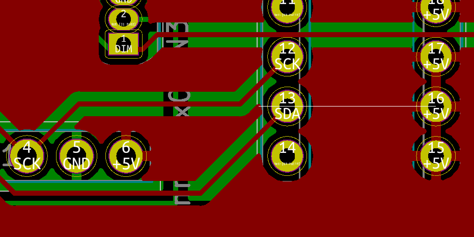
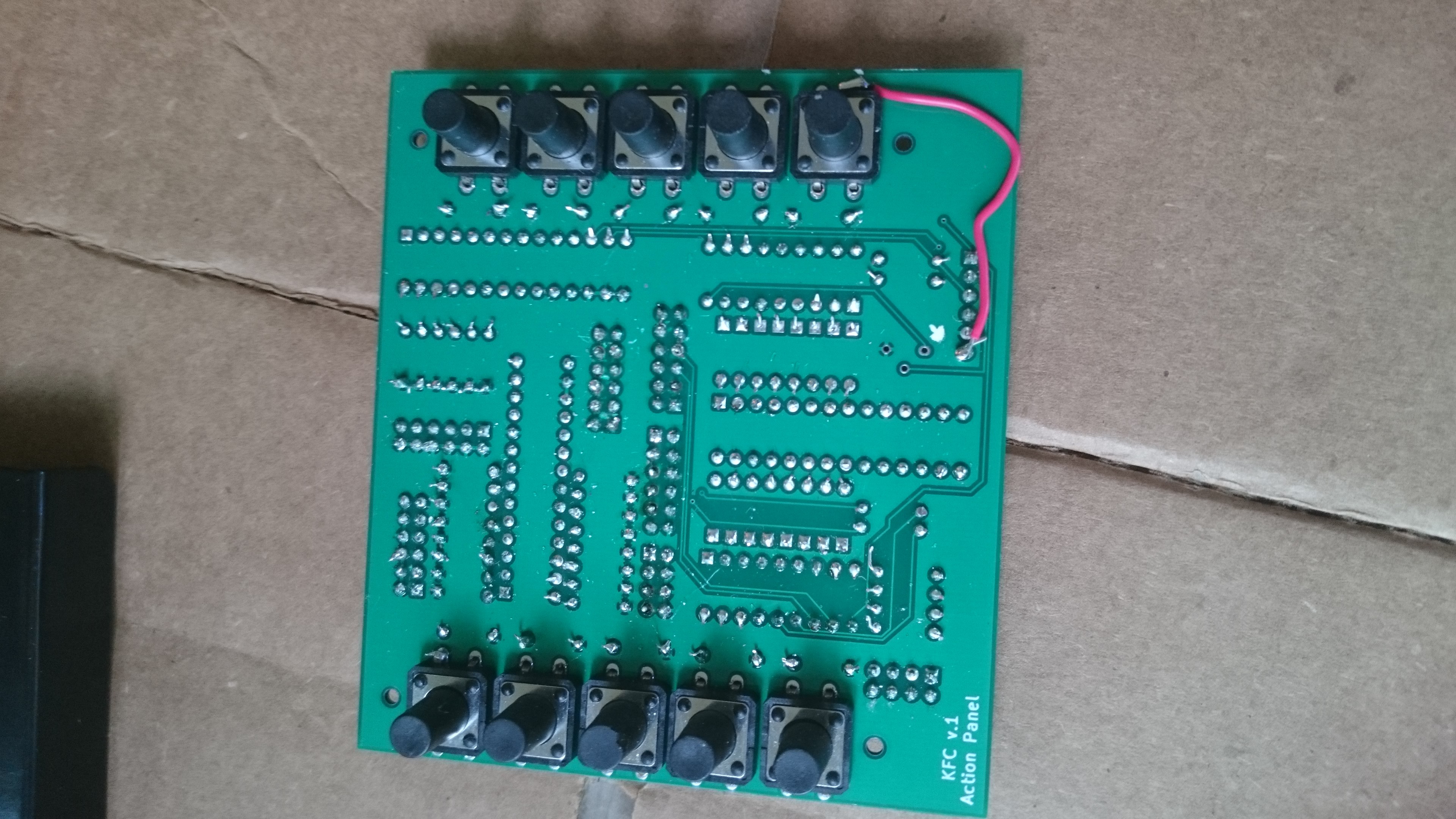
My power pin isn't connected to the power plane! I have some unconnected pins because they were going to be connected by my switches, but I must have missed this one. Too bad. Crude problems sometimes merit crude solutions:
Ok now when I plug it in I get:
I'm awake!
Started Wire
Testing 32 returned 0
Testing 33 returned 0
Done testing, detected: 2
0x20A: 00000000 0x20B: 00000000 0x21A: 00000000 0x21B: 00000000
0x20A: 00000000 0x20B: 00000000 0x21A: 00000000 0x21B: 00000000
...
0x20A: 00000000 0x20B: 00000000 0x21A: 00000000 0x21B: 00000000
0x20A: 00000000 0x20B: 00000000 0x21A: 00000000 0x21B: 00000000
0x20A: 00000000 0x20B: 00000100 0x21A: 00000000 0x21B: 00000000
0x20A: 00000000 0x20B: 00000100 0x21A: 00000000 0x21B: 00000000
0x20A: 00000000 0x20B: 00000100 0x21A: 00000000 0x21B: 00000000
0x20A: 00000000 0x20B: 00000100 0x21A: 00000000 0x21B: 00000000
0x20A: 00000000 0x20B: 00000000 0x21A: 00000000 0x21B: 00000000
0x20A: 00000000 0x20B: 00000000 0x21A: 00000000 0x21B: 00000000
0x20A: 00000000 0x20B: 00000000 0x21A: 00000000 0x21B: 00000000
0x20A: 00000000 0x20B: 00000000 0x21A: 00000000 0x21B: 00000000
0x20A: 00000000 0x20B: 00000000 0x21A: 00000000 0x21B: 00000000
0x20A: 00000000 0x20B: 00000000 0x21A: 00000000 0x21B: 00000000
0x20A: 00000000 0x20B: 00000000 0x21A: 00000000 0x21B: 00000000
0x20A: 00000000 0x20B: 00001000 0x21A: 00000000 0x21B: 00000000
Progress! We hit both chips. As we press the buttons, the corresponding registers switch to 1s. Then we just need to test each action button and all the other inputs via a jumper.
Action button 6 was not working because of a bad solder join. Testing also showed that not one of the jumpered switches was working. This is due to another embarassing error, unfortunately not one I can fix here:
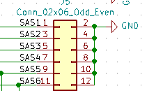
The switch jumpers are hooked in to the ground plane instead of the 5v. So jumpering them doesn't change the state of the MCP pin at all. No wonder they don't work. This will also affect the throttle panel :( . So it's back to the drawing board with those!
Discussions
Become a Hackaday.io Member
Create an account to leave a comment. Already have an account? Log In.
Actually - at least for testing purposes - I should be able to just connect the switches to 5v at a different point in the circuit. It should work fine, just a bit messy.
Are you sure? yes | no