Close
0%
0%

My own "a million times clock-clock"

cheap rip off from the art installation of Humans Since 1982

Public Chat
Similar projects worth following
As many others, I have seen the very cool clock clock called "a million times" made by "Humans Since 1982". But I don't need it, so I will not spend more than 10kEUR :-)
However, to do one on my own... could be interesting. So let's start, let's resign, let's try again... You know it ;-) Anything else than straight forward.

I try to share some of my attempts to you. Any comment is warmly welcome!

As this is a "copy" of somebodys work who spend a lot of thinking and money in it, my work is purely for the engineering challenge. It's not for sale or any other commercial use! This would not only be unfair, but in addition, the design is protected with a copyright by "Humans since 1982". If you want to have one for you but you don't want to make it on your own, check out the website of "humans since 1982" :-)

How does it work?

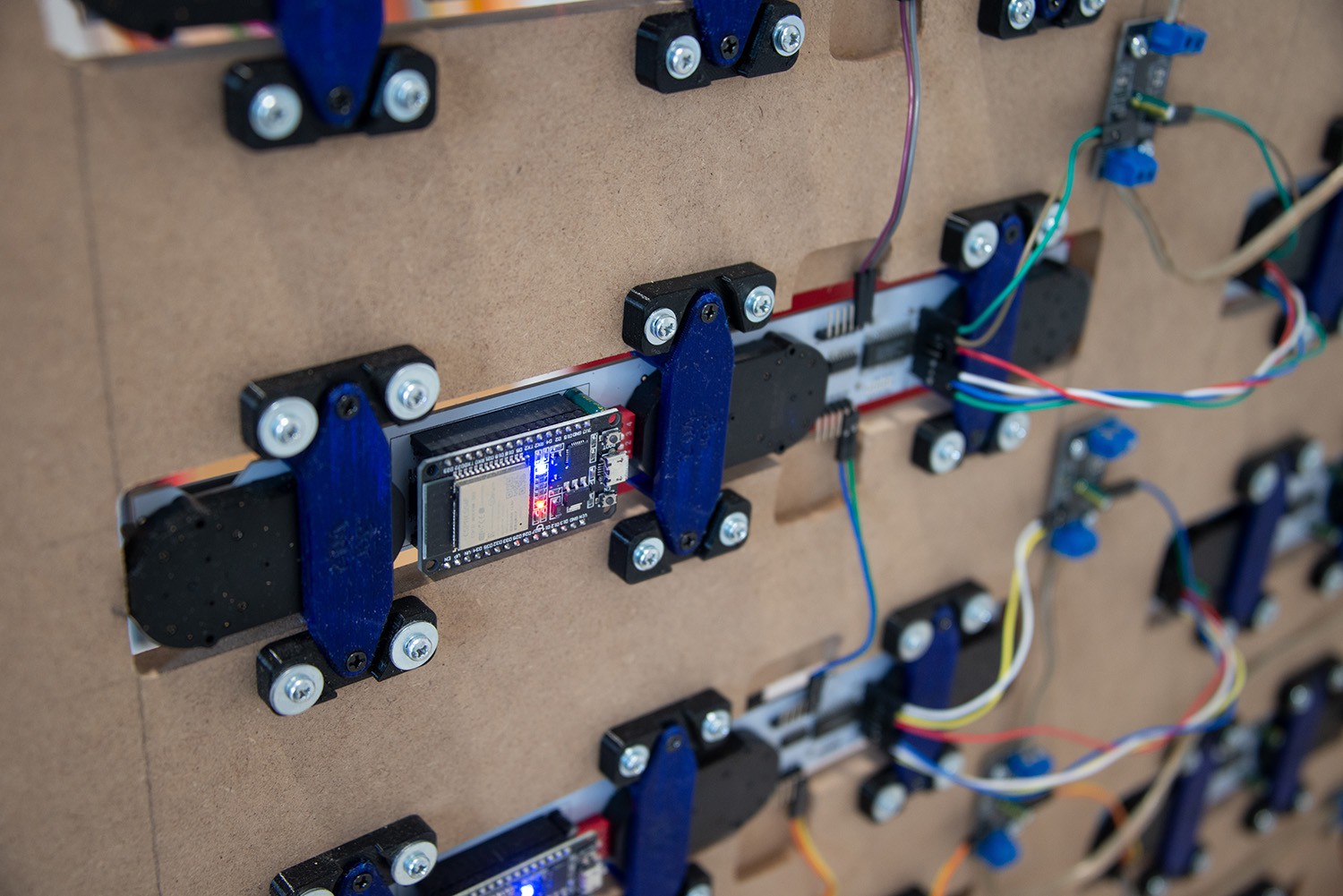
I have one master controller (ESP32) which has all the moves and forms saved in the code. 

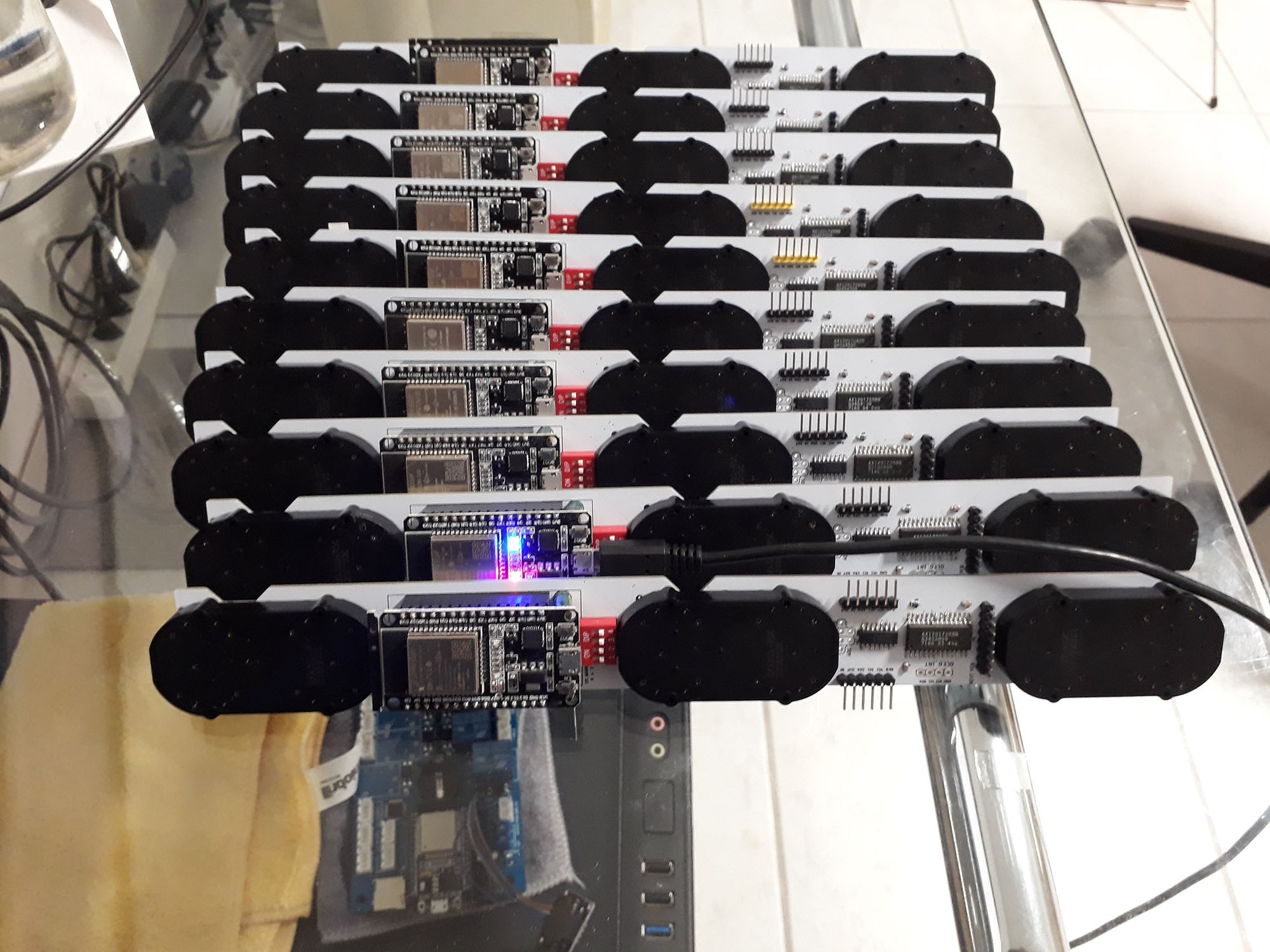
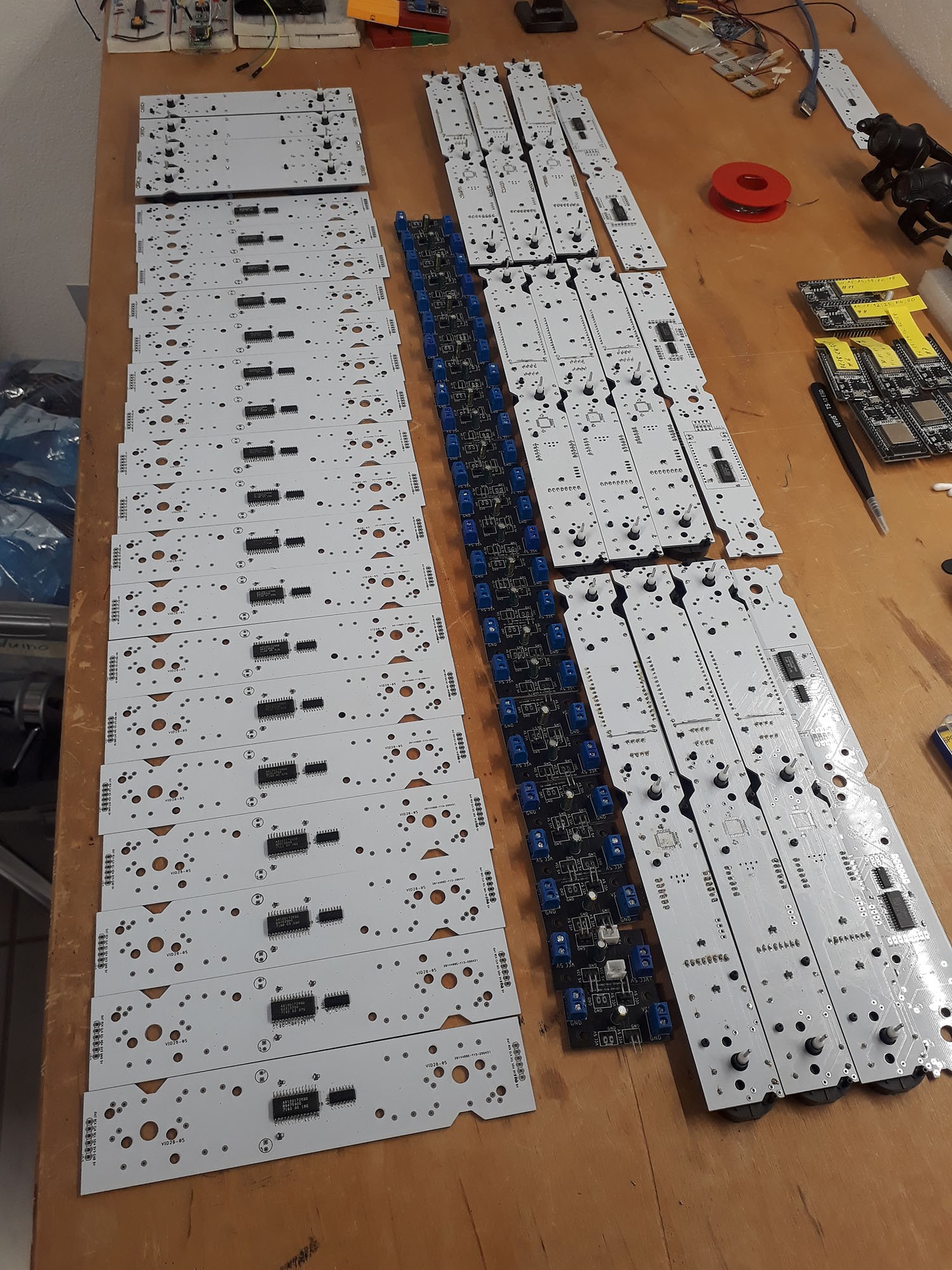
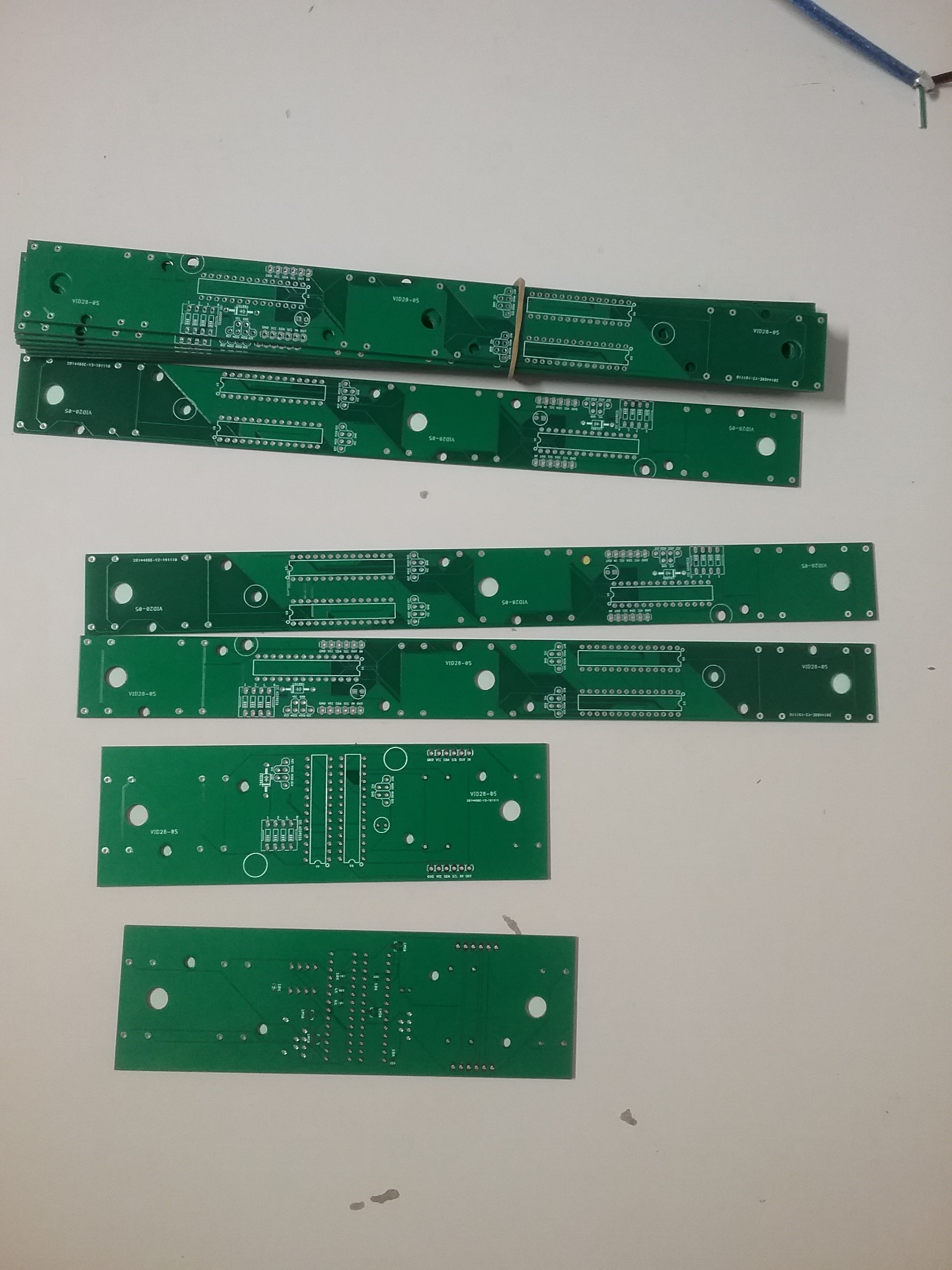
Every Motor (VID28-05) has one ATMEGA328P Microcontroler which is a slave on the I2C bus. Every Slave has his own address on the bus.

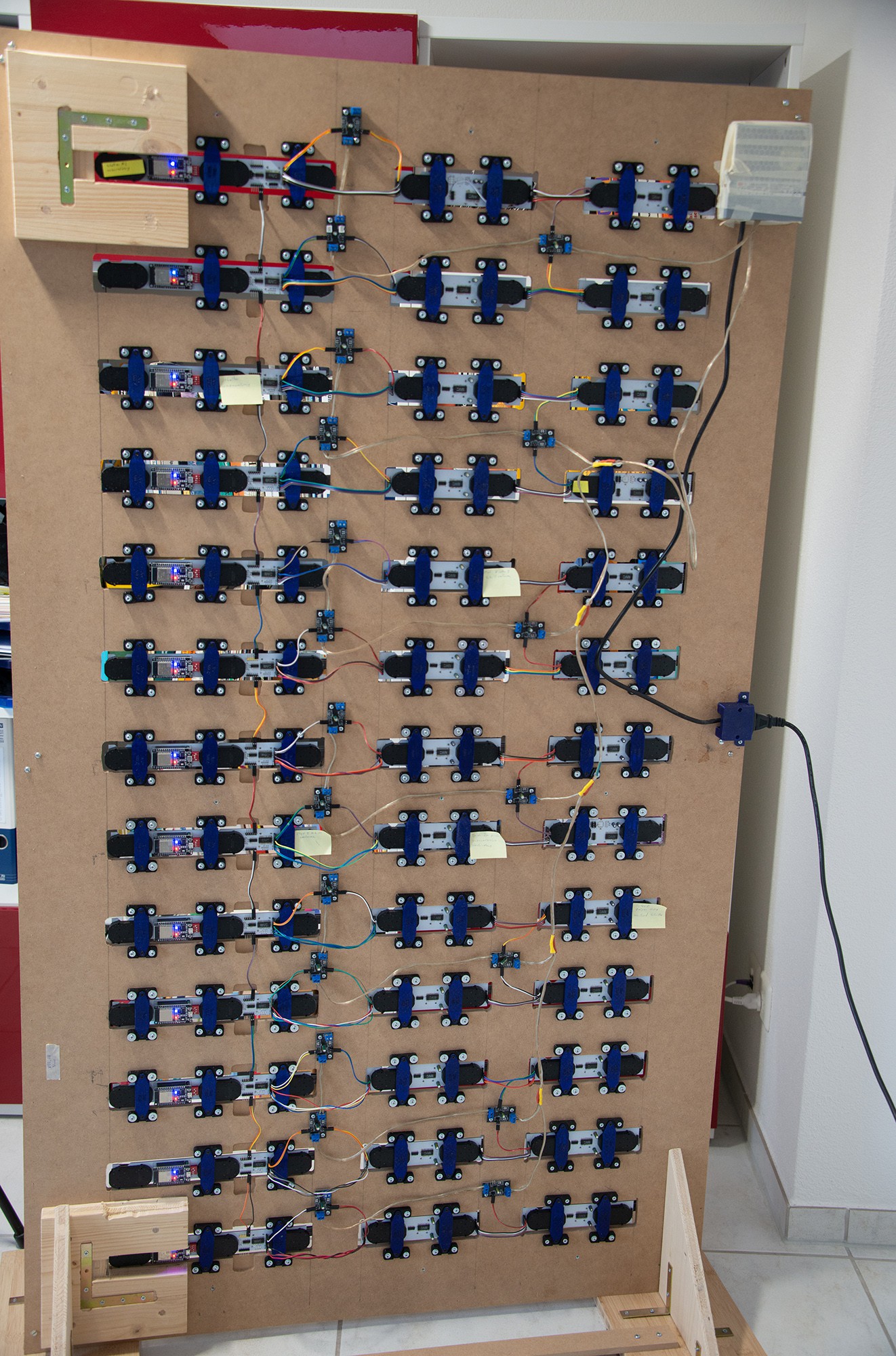
With an IR control I can start the movements. For this, the ESP32 (Master) sends out the target positions for each handle via I2C. As soon as this is done, he sets a pin to HIGH so that all slaves start to move. As soon as all slaves reached their position, the master sends out the next etc. 

The flaws of this approach is clearly the noise and the precission of the VID28-05 steppers. So now I try to build the same with the X40 steppers. 

The code ist very simple and offers a lot of freedom. However it has to be improved to be more "user friendly" :)

V08_Hackaday.zip

Vertical PCB arrangement with 5 VID28-05 motors controlled by a master MCU for a first run

Zip Archive - 94.68 kB - 12/29/2019 at 17:15

Download

V07_00_FirstRun.zip

First run with the new library MotorVID28_05

Zip Archive - 19.81 kB - 09/15/2019 at 14:43

Download

2019-08-26_Test_PCB.zip

PCB and Arduino code for the Video dated 26-08-2019. Only a test of the slave. No communication with master

Zip Archive - 33.59 kB - 09/02/2019 at 21:05

Download

Eagle_PCB_Slave.png

Eagle schema of PCB of slave

Portable Network Graphics (PNG) - 67.26 kB - 12/08/2018 at 17:45

Preview
Download

Wiring_Master.png

Wiring of Master

Portable Network Graphics (PNG) - 2.29 MB - 12/08/2018 at 17:43

Preview
Download

View all 10 files

  • 1 × ESP32 as Master
  • 9 × VID28-05 stepper motors
  • 9 × ATMEGA328P MCU as slave

  • Final version

    chaterrony08/01/2022 at 10:04 0 comments

    Final version is done. Under the following link you can see the video of the demo run.

    I hope this is an inspiration to others. Remember, credit goes to HumansSince1982. It is protected by copyright and I can and will not share some critical information. The documents/information you find in this project documentation is also information which is available on other project logs.

    It's a great project to learn many skills. For me, the main learning was that it is a big difference if you design one part or like here for 182 handles. Every small error multiplies up to 182 times and it is really worth the effort to test and work structured! :-)

    Have fun and a good time!

  • Time for an update - how to start 2021

    chaterrony01/03/2021 at 17:07 6 comments

    After quite some while, I can present some progress. 

    All 182 handles are working fine. I controll them over 13 ESP32 MCU. Between the "master" and the "slaves" (I know, this does not exist with ESP-NOW) I communicate with ESP-NOW. In future, an ANDROID app will controll the master.

    The communication between the slave ESP32 and the stepper drivers, is via I2C and - don't follow this!! - Dupont wires.

    I learned the hard way, what seems to be obvious to all experienced makers... 

        Dupont = prototyping
        Dupont = NOT for large scale and/or permanent installations!

    They are simply not reliable. So I need to change to JST-XH... All of them... outch :-(

    The PCBs with the motors are hold by a bracket which is screwed to a support on the wooden frame. With this, I can exchange easily individual PCBs later. Also they are interchangeable. I think, this almost 100h of 3D printing was worth the effort.

  • Version end of the year - not End of the project ;-)

    chaterrony12/29/2019 at 17:37 0 comments

    So, the year is ending and I have a little progress to show. It's like 10 step forward, 9 backward… Anyhow:

    The new PCB's arrived, I figured out all errors I did and the motors are running. I have also got the first set of 3D printed handles (PLA) which fits more or less on the motor.

    I have two different PCB because this is the maximum size I can get with the Autodesk Eagle free version. Otherwise I need to pay (and the project is expensive enough…). So I have one PCB with 3 motors and one with 2 motors. At the end, the installation will have 5 motors vertically and 11 (or 13) horizontally.

    What does it do now?

    First the lower handle rotate until it passes a hall sensor. Every handle has a hall sensor and a different offset to know where is zero position (12 o'clock). After this, the handle goes to 3 o'clock to avoid an interference with the upper handle. As the upper handle is quite far away from the hall sensor, the magnetic field change is very little and therefore the other magnet shall not be too close.

    After this, the handles go to 12 o'clock. As soon as they are there they give the signal that they are ready. When all are ready, the master gives a new position via I2C for all MCU (every motor has a MCU with a different I2C Address). The new positions have the informations:
    - delay prior to run
    - new position
    - speed
    - accelleration

    Issues:

    - Some bugs on the PCB :-(

    - The magnets are too close. One handle can push the other slightly

    - One broken motor was replaced, two other seems to have problems with the gear too. I am not sure if it's because I treated them bad or if they wear so fast? I hope not!
    You see the damages on the handle of the motor "2" with the sticker on it. The gear is sometimes jumping a little bit when the handle should turn upwards.

    Changes for the next version:

    - Hall sensors further away

    - upper handle closer to the PCB (for the signal of the hall sensor)

    - Test with other motors (X40)

    The video to show how it works is here:

    All files are in the document section "V08".

    So I am always open for ideas, inputs and questions :-)

    Wish you a happy new year!

  • Next attempt with new library

    chaterrony09/15/2019 at 14:42 0 comments

    So, after the last attempt (without acceleration) worked, I realized that the accelerations are hard to compute for two handles in parallel for an ATMEGA328 with the accelstepper library. The square root calculation takes a lot of time. So I have two solutions:

      A) one MCU per handle (this will be expensive and a pure Overkill, but it has proven to work well)

      B) change the way to calculate the acceleration

    So obviously I have chosen B...

    The approach for the following discussion is always, to have a certain frequency at which the programm is run (at the moment at 0.6ms) and it checks every time if there is a move to be run. Means, a speed of "2" makes a step every seccond tick. A speed of "4" makes a step every 4th tick...

    As first, I calculated with a simple formula the acceleration and deceleration. Formula for deceleration:

    amountOfTicksToAccelerate)*accelerationSpeed/(targetTick-actualTick).

    This Formula works very well for acceleration, but at deceleration it is highly risky that the computed values will not match exactly and it ends up in non-matching position vs. timing. 

    So I made it the "easy" - and for programmers horrible - way. I saved an array for the acceleration. After how many ticks, shall the next step be made. The array is 50 items long:

    accelArray[50] = { 12,11,10,10,9,9,8,7,7,6,6,6,5,5,4,4,4,3,3,3,3,3,2,2,2,2,2,2,2,1,1,1,1,1,1,1,1,1,1,0,1,1,0,0,1,1,0,0,0,1 }

    The first move is after 12 ticks. Tick timing is 0.6ms, so after 7.2ms the first move is done. The seccond step is after 11 ticks (6.6ms) etc. To decelerate I run the array backward. The main curve was calculated and then tested with different speed/acceleration combinations until it looked smooth. 

    So the acceleration phase with acceleration value of "1" ist always 50 steps. If you choose acceleration of "3", then it runs the array 3 times. Means, 3 times after 12 ticks, then 3 times after 11 ticks… 

    It's not nice, I know, but at least I was able to make it work smooth and reliable.

    Here is the video: https://youtu.be/93-9P3XuW-w

    The code and library is uploaded in the document section. 

    Any input/suggestion is highly welcome! :-)

  • New PCB arrived

    chaterrony08/26/2019 at 19:25 2 comments

    So, summer is ending and the new PCB arrived after the vacation. The Hall sensor works pretty well. However, the speed is an issue at the moment. Not that I want to run the handles very fast, but the max speed (if both are running at the same time) is roughly 9s/turn. And in addition, when one handle is running at constant speed, it changes speed when the other is accelerating. Seeing all the other attempts on the internet, I doubt that the ATMEGA328p is at his limits. But what is then the reason??? 

    Video can be seen here: 

    And yes, I did an error on the PCB, therefore I had to handsolder a little bit ;-) Looking for half a hour on the PCB prior to manufacturing is obviously not enough...

    Have a good start of the week!

  • Home function with hall sensor tested

    chaterrony04/27/2019 at 22:10 0 comments

    Finally, I managed to work again on the prototype. The zeroing of the handle seems to be a Problem. I did not find much Details on all the other Projects which attempted this. My Approach was now with a Hall sensor and a small magnet. I was surprised how precise it can work on a distance of 5mm. It works also quite good on a larger distance. 

    Now I have to make new PCB and replace all my handles with the new PCB. Let's see how this will work...

    You find the Video of the test here: 

  • First prototype working

    chaterrony11/30/2018 at 15:59 0 comments

    After many attempts, many PCB scraped... here is my first working prototype. However, there seems to be many issues with it.

    As motors I have used the cheap VID28-05, but trying now also the X40 motors.

View all 7 project logs

Enjoy this project?

Share

Discussions

asaf.el wrote 04/14/2023 at 16:51 point

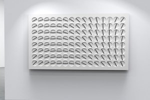
Very impressive project, i don't understand how are you controlling each hand of the clock with one motor?

  Are you sure? yes | no

Lucas wrote 02/02/2023 at 08:27 point

Thanks for the information, your project helped me a lot when I try to make my version, please take a look of my project if interested https://hackaday.io/project/189332-a-million-times-288-clone

  Are you sure? yes | no

Knut Kumpe wrote 07/22/2021 at 22:50 point

is it possible to buy a Version of the clock?

  Are you sure? yes | no

xnico31 wrote 04/09/2020 at 06:30 point

nice works Keep Going : ) check mine https://www.youtube.com/watch?v=6xYojza_dPQ 

  Are you sure? yes | no

chaterrony wrote 04/09/2020 at 16:59 point

white on black? looks cool! Do you work with the X40 stepper or the VID28.05?

  Are you sure? yes | no

dirkschlecht wrote 04/28/2021 at 13:30 point

Hi xnico31. Great work. Do you have a description of it?

  Are you sure? yes | no

rioderaca wrote 02/02/2020 at 00:56 point

So you’re powering the motor straight from the ATMEGA328P, right? 

  Are you sure? yes | no

chaterrony wrote 04/09/2020 at 16:58 point

Yes, but I change this now. It's a huge amount of MCU which are required. But until now it worked always like this and the steppers are designed to be connected directly to an MCU. You have roughly 20mA per coil, so perfect for an ATMEGA328P.

  Are you sure? yes | no

rioderaca wrote 02/02/2020 at 00:50 point

hi, this is interesting. Keep at it, am curious about the end result. Looks like quite some commitment is needed. 

  Are you sure? yes | no

Mike Szczys wrote 12/03/2018 at 16:42 point

Just watched the first proof of concept video. This is super promising! You mention there's many issues, but this is further than I've seen anyone else make it on building their over version of this clock. Keep going... this is awesome!

  Are you sure? yes | no

Similar Projects

Does this project spark your interest?

Become a member to follow this project and never miss any updates