 John
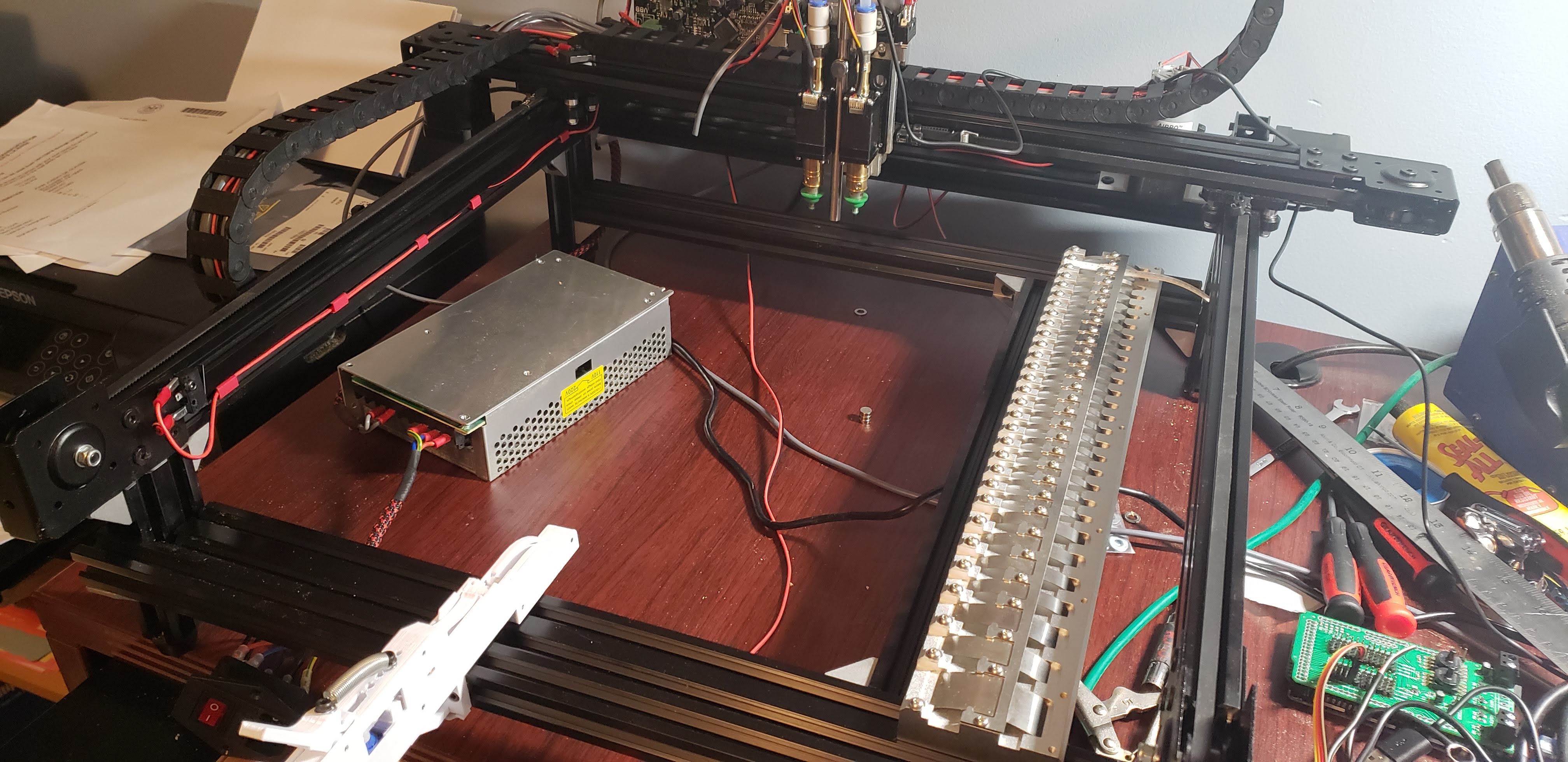
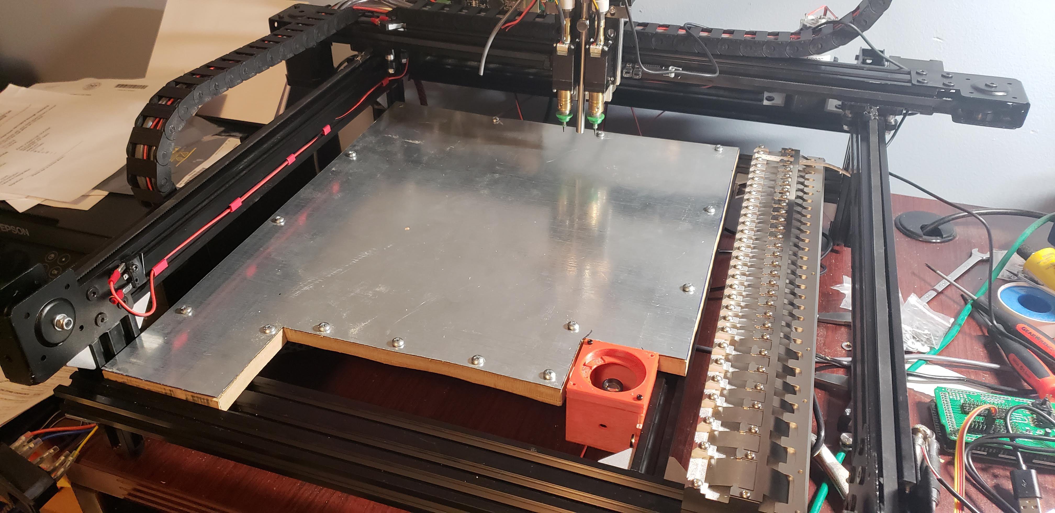
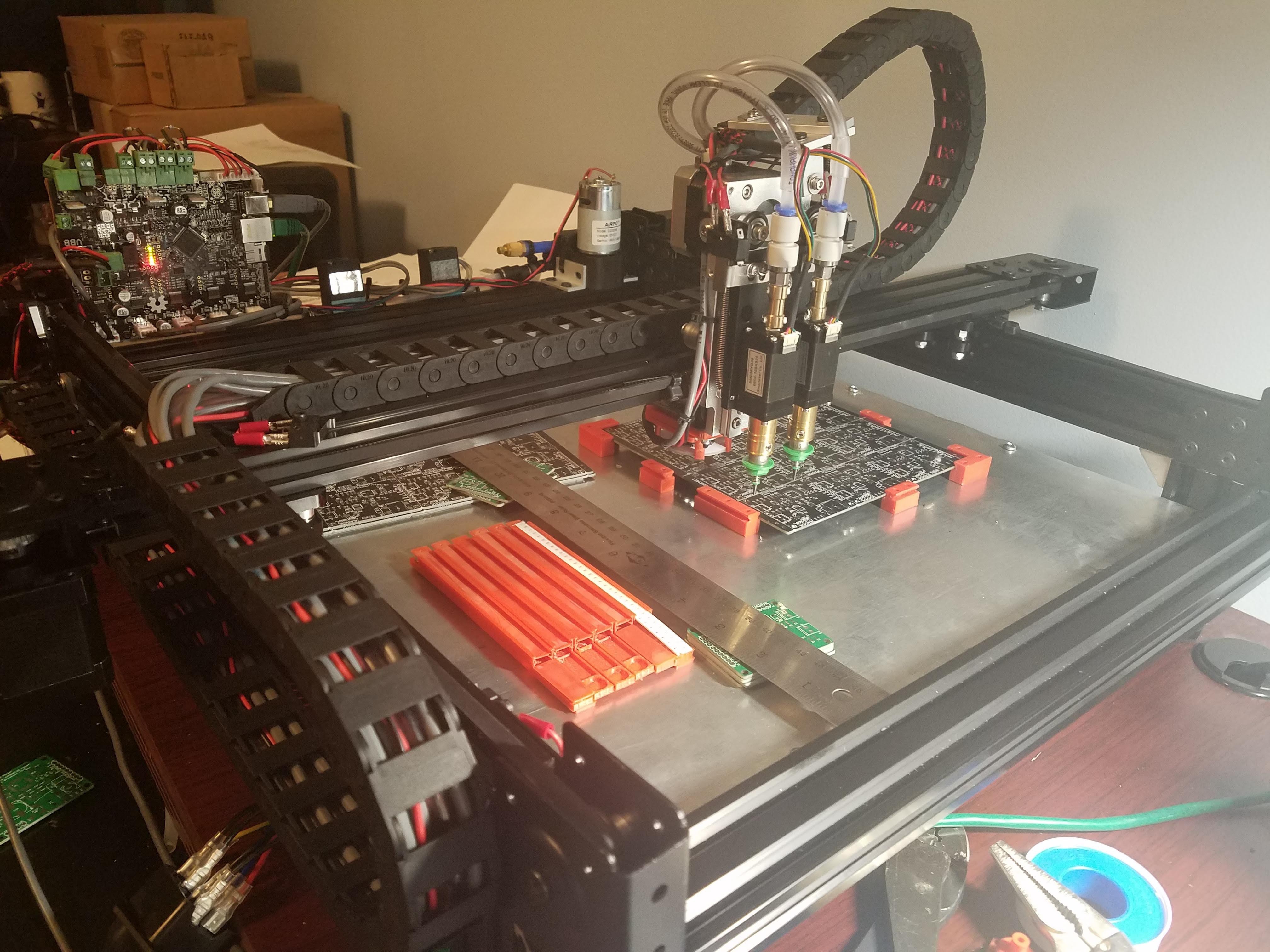
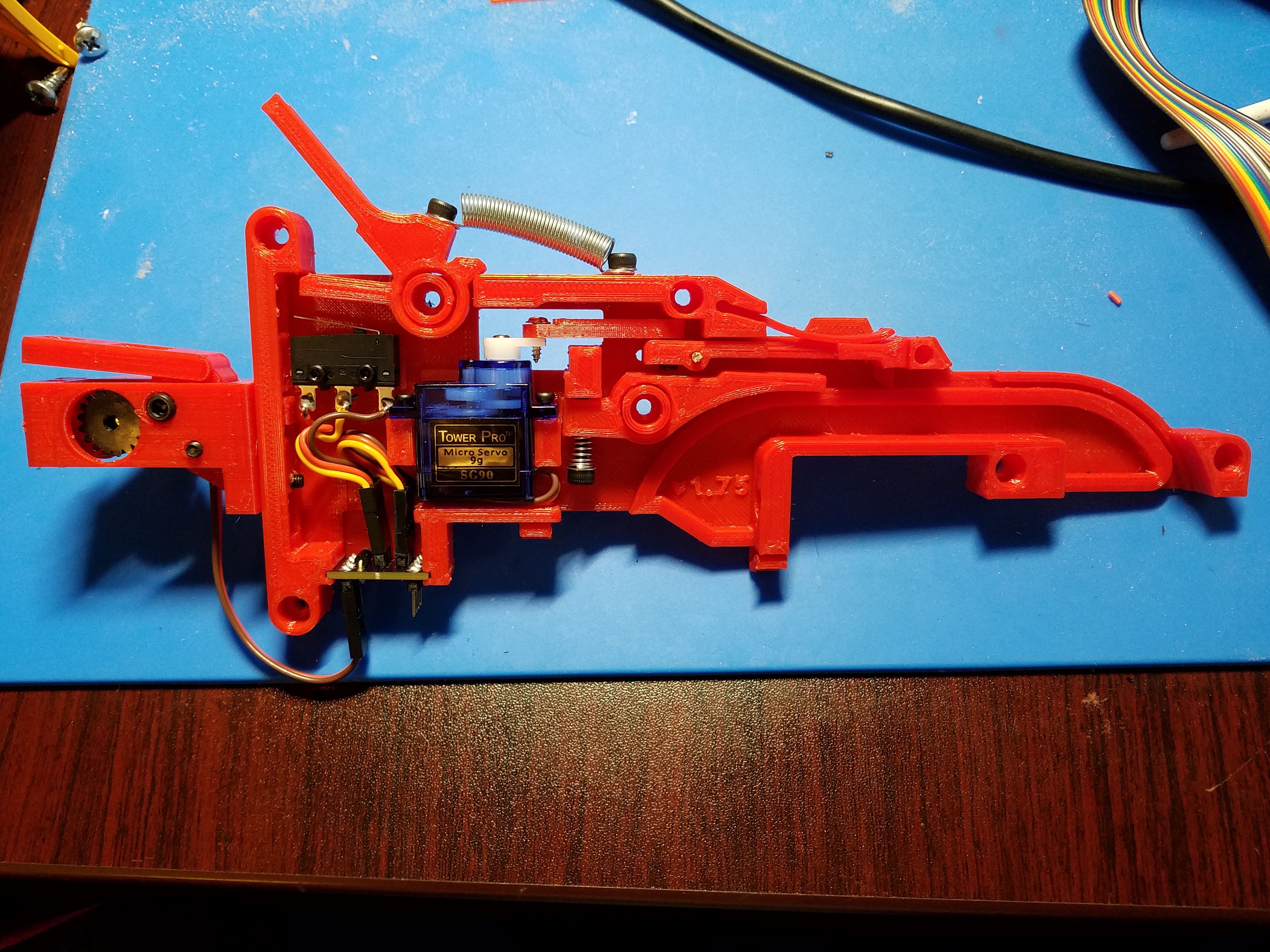
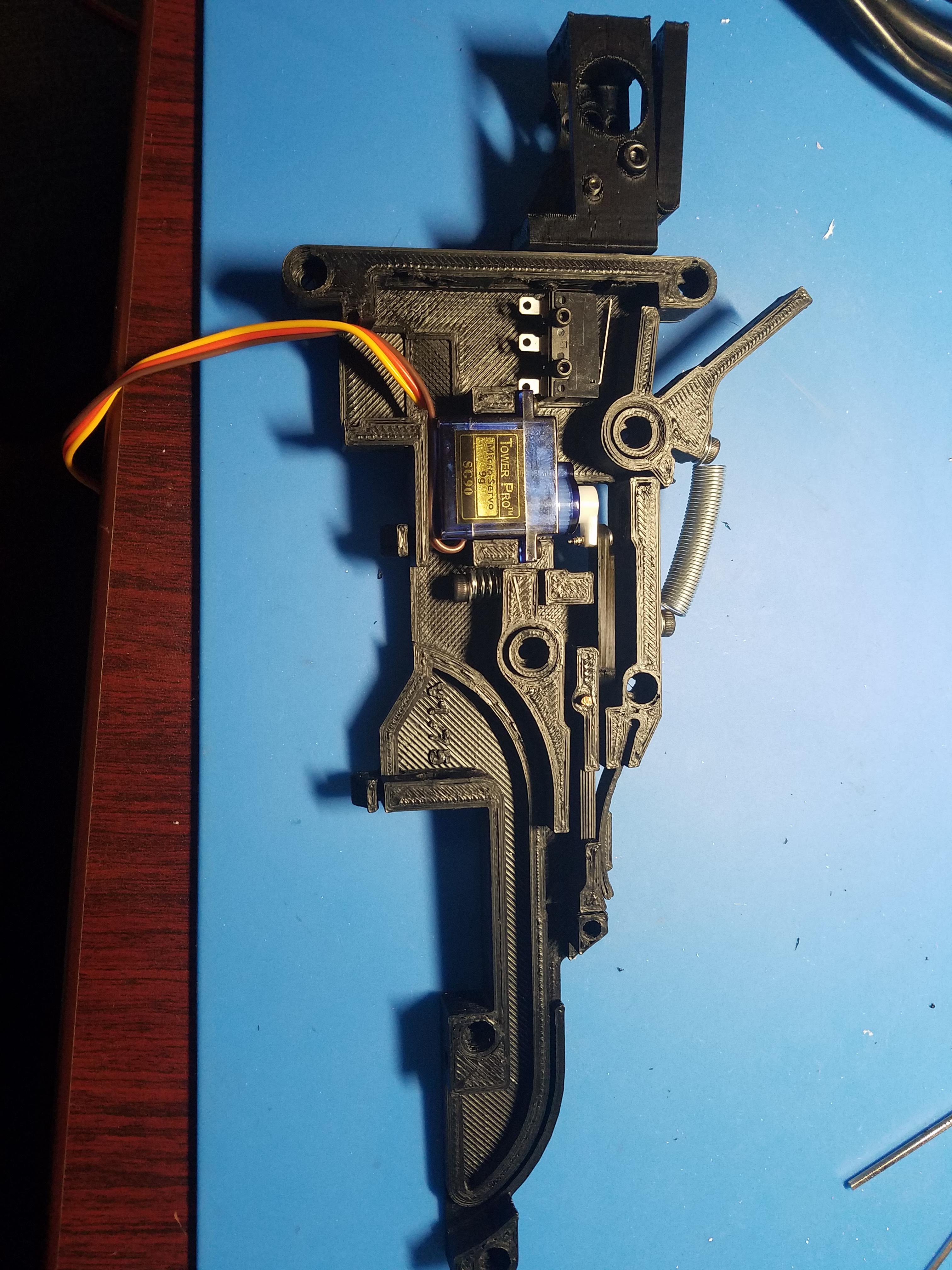
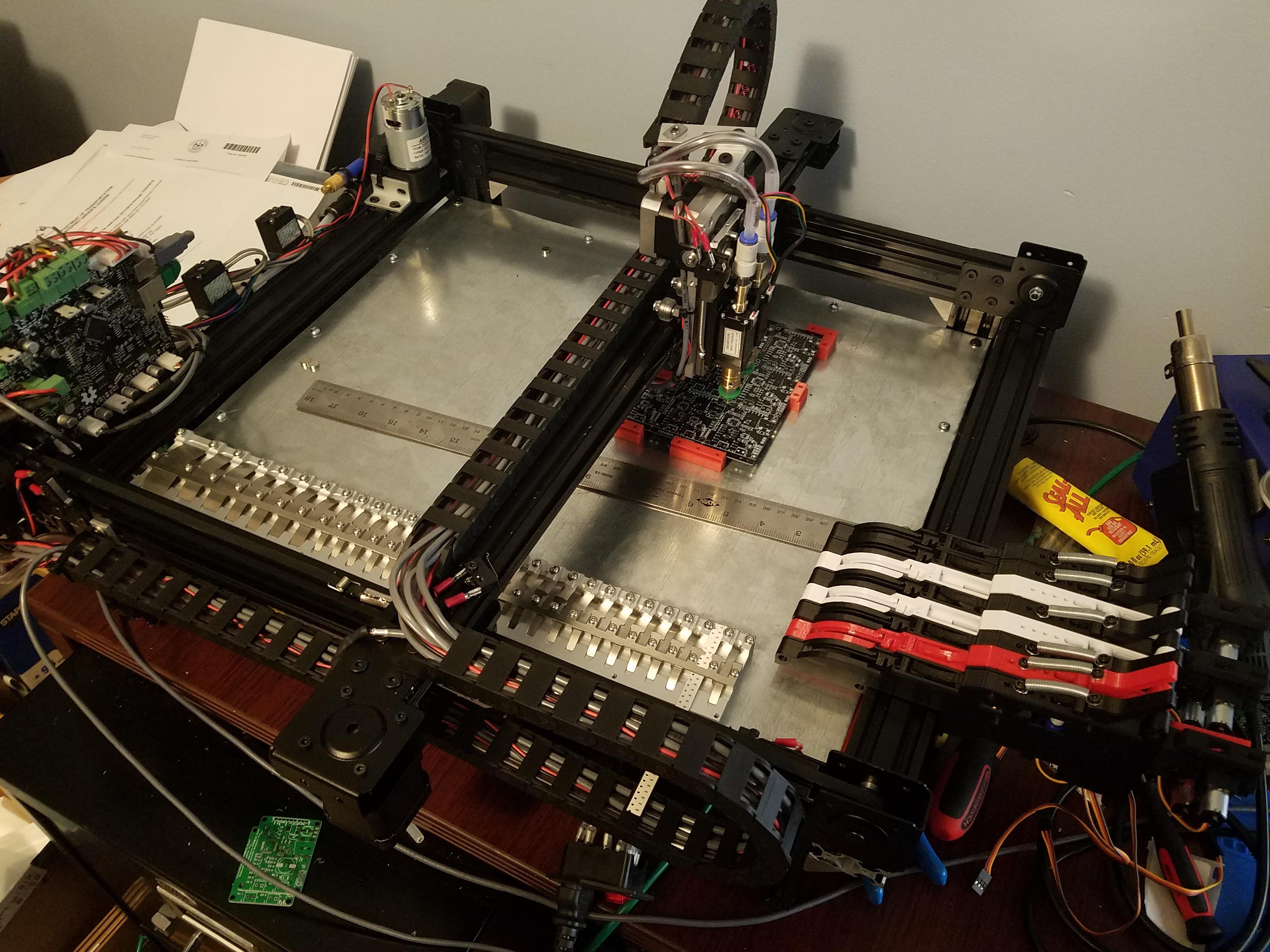
JohnThis PNP build pulls ideas from many different machines that came before this one. I used the OpenPnp Openbuilds as a starting point. I wanted to have a usable machine without spending thousands, while being able to add things (like auto feeders, and a nozzle changer) as needed.
0%
0%
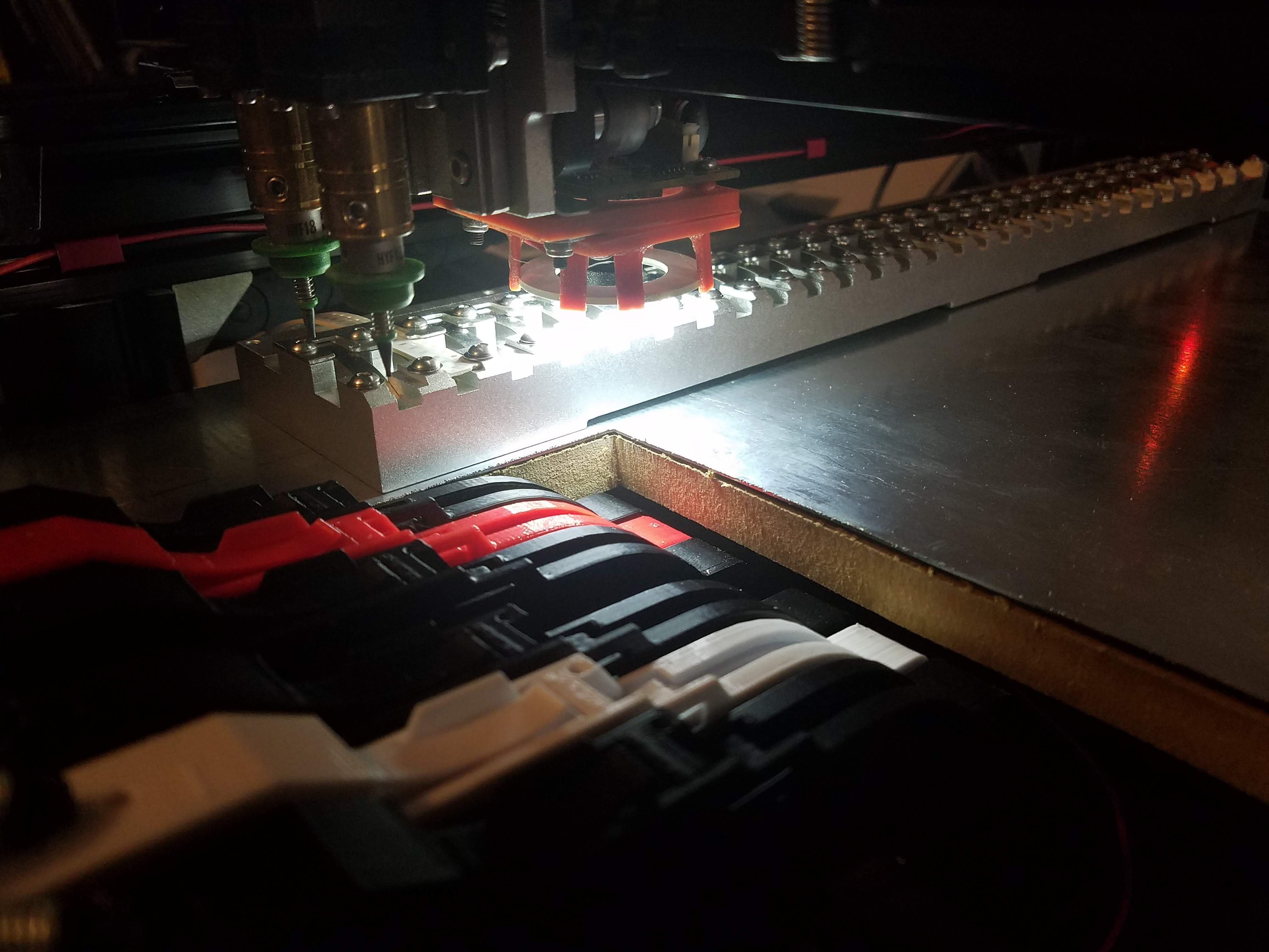
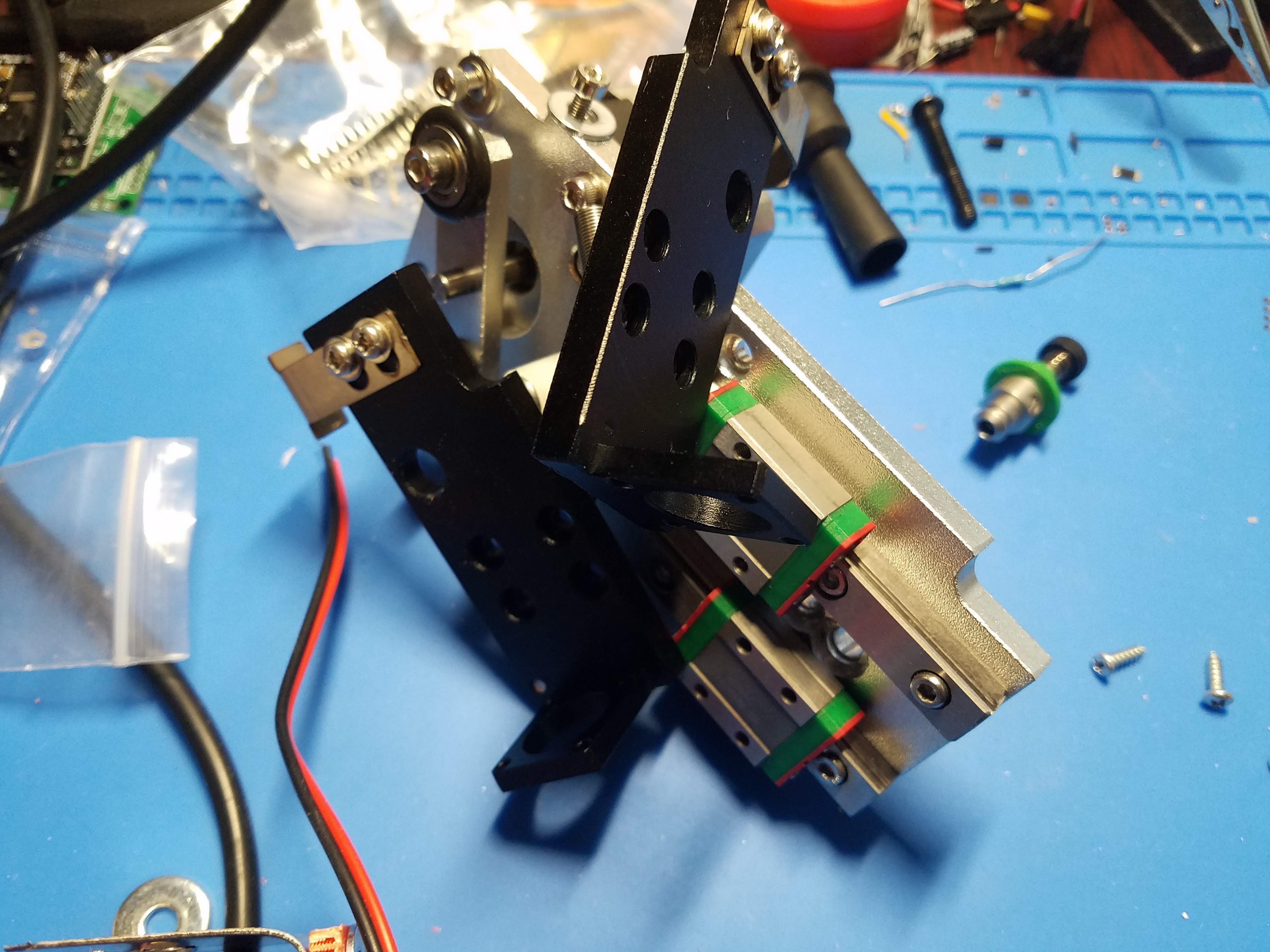
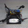
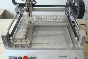
Pick and place machine - Smoothieboard/OpenPnp
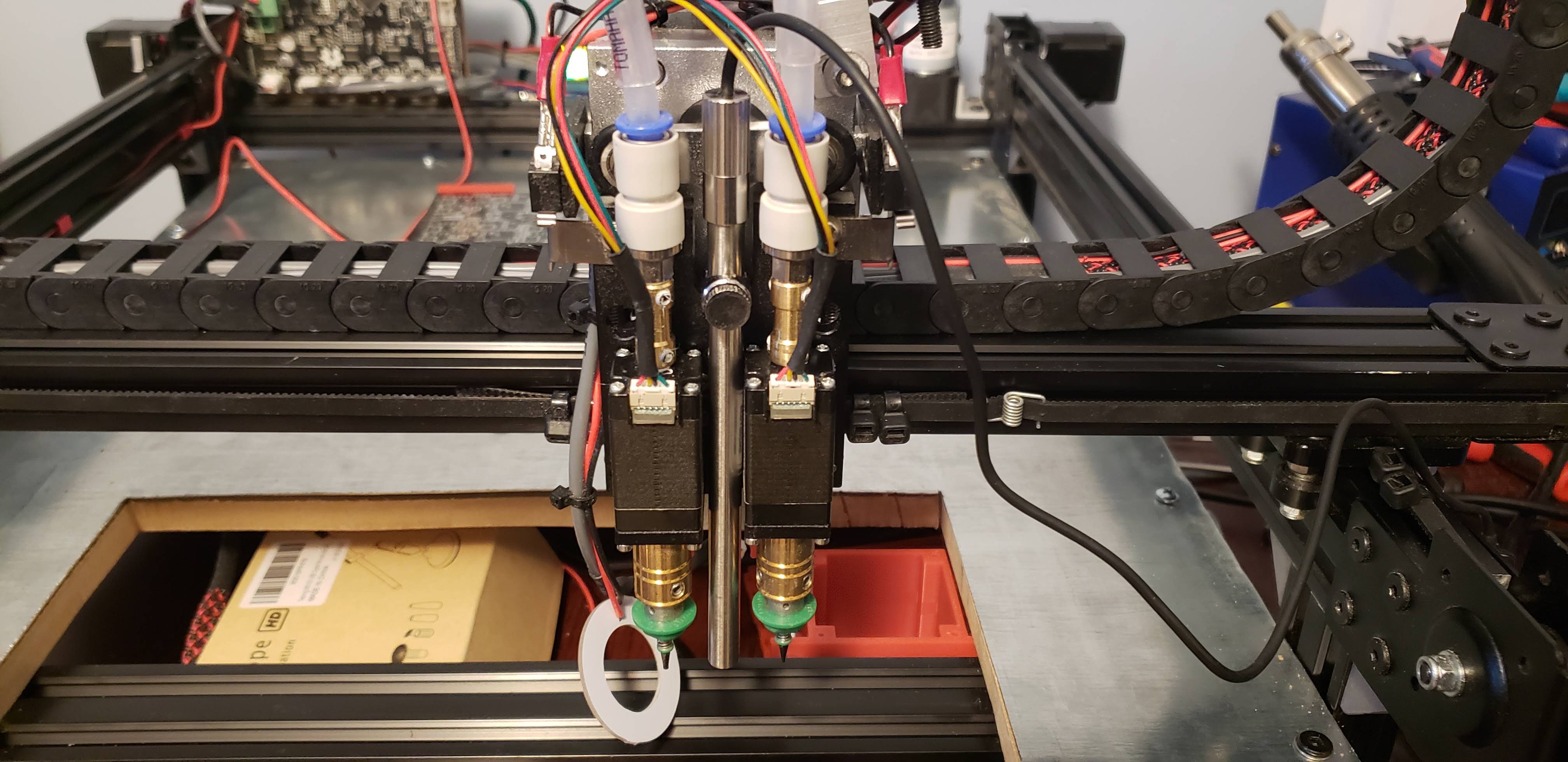
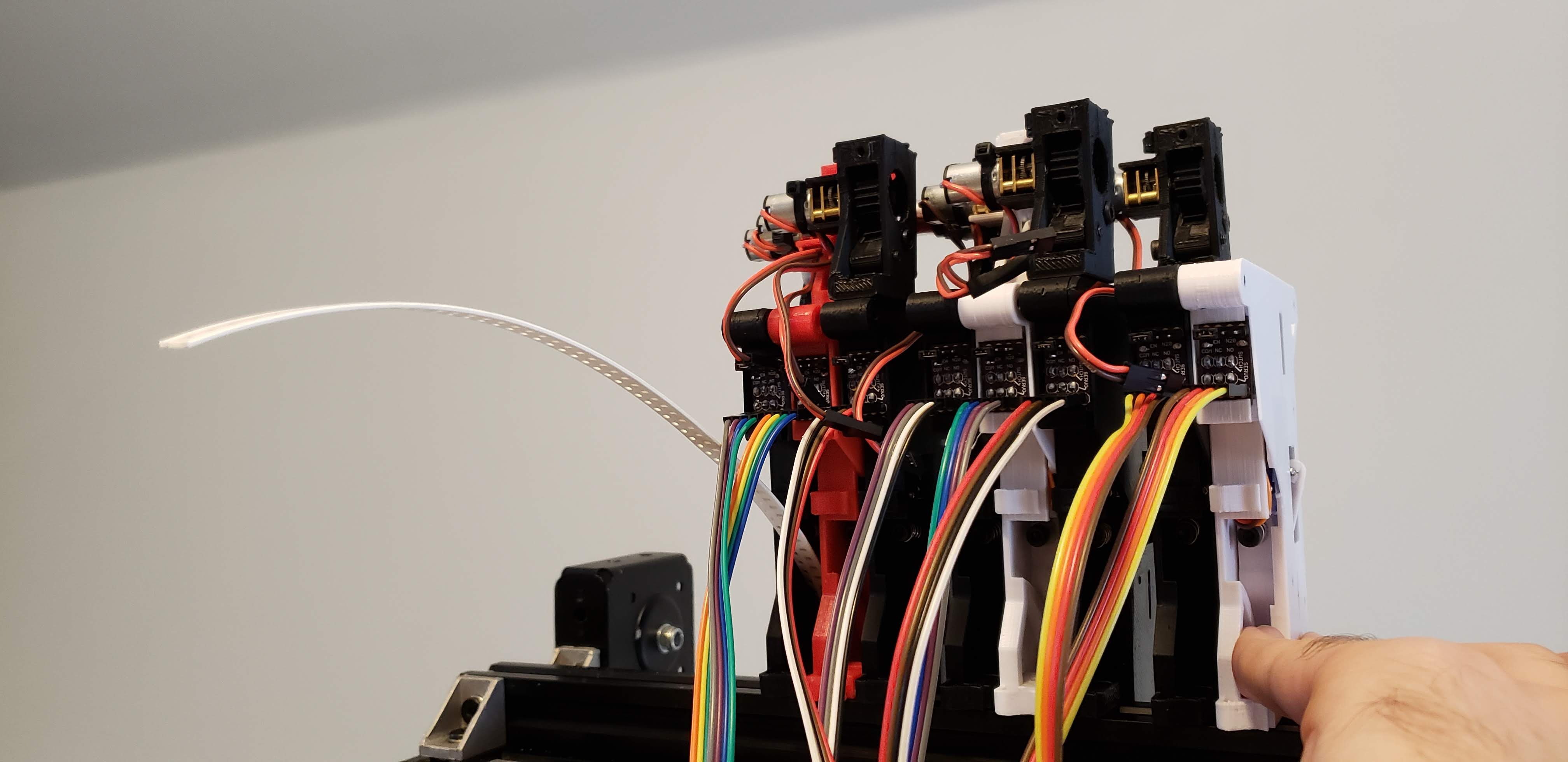
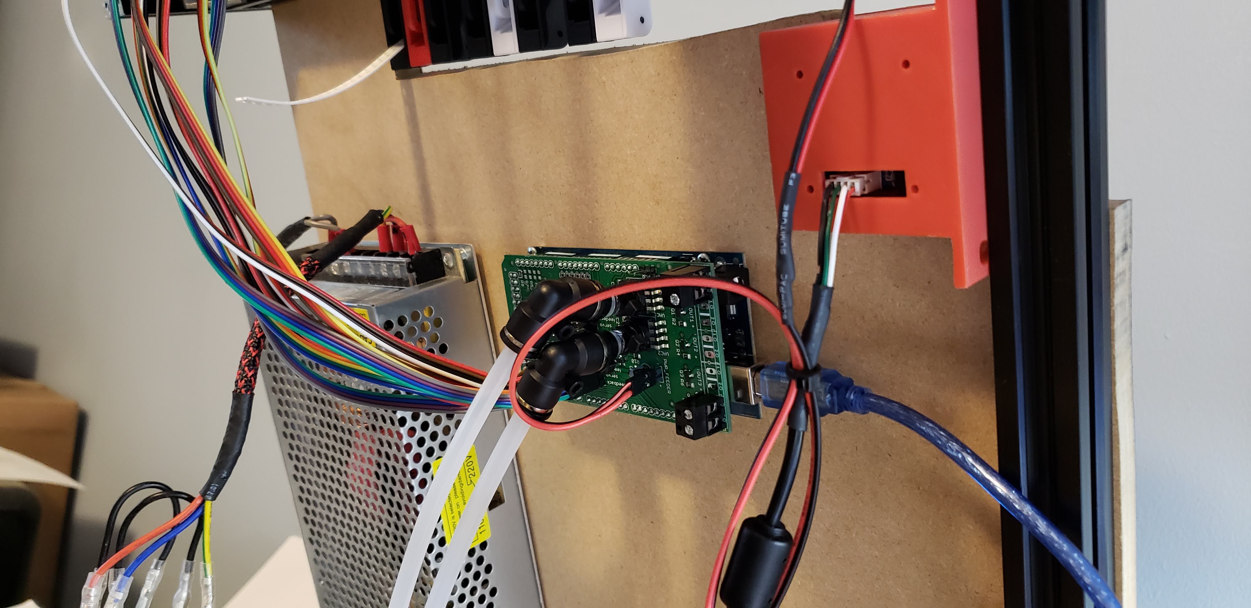
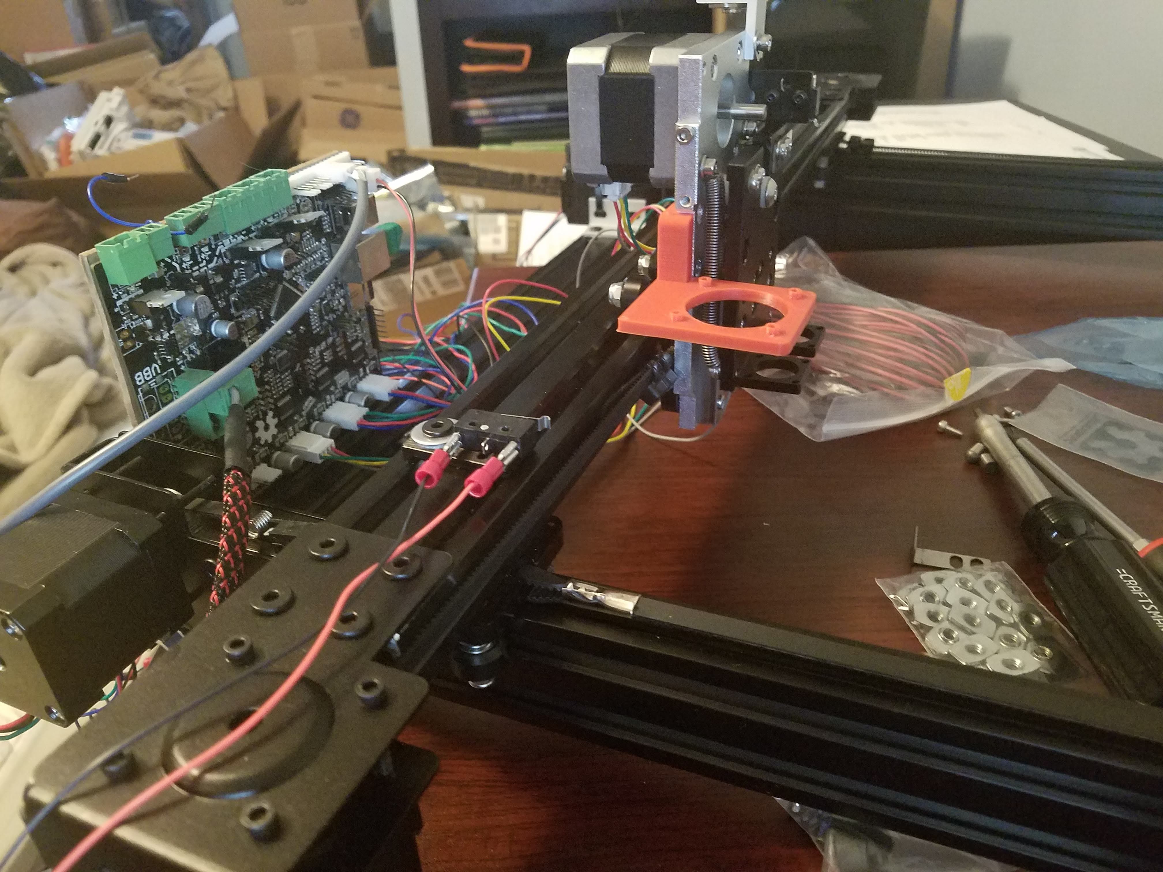
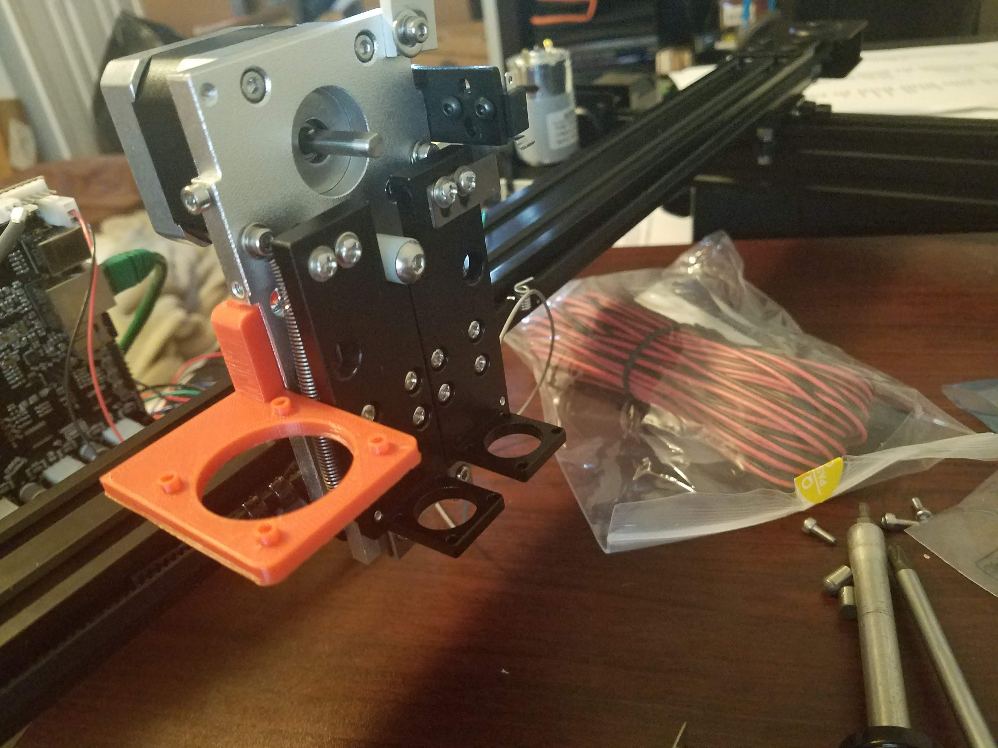
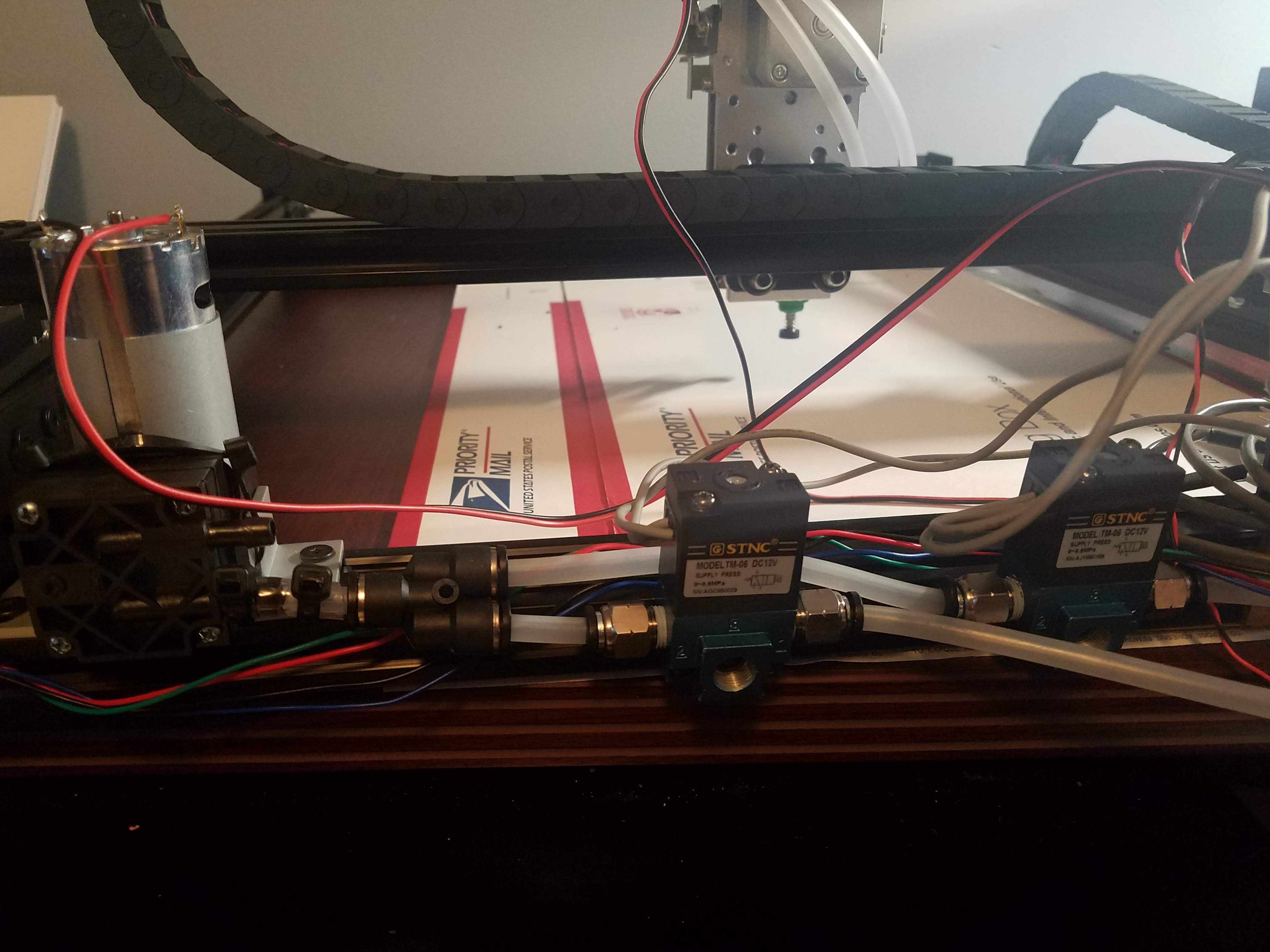
A dual head PNP machine that uses Openbuilds hardware, a Smoothieboard controller, dual camera vision, automatic/drag feeders, and OpenPnp
Become a Hackaday.io member
Already have an account? Log in.
Just one more thing
To make the experience fit your profile, pick a username and tell us what interests you.
Pick an awesome username
hackaday.io/
Your profile's URL: hackaday.io/username. Max 25 alphanumeric characters.
Pick a few interests
Projects that share your interests
People that share your interests
 dar.ryl
 N. Christopher Perry
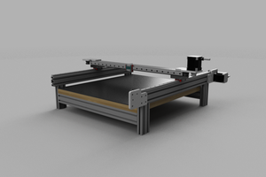
 anthony.webb
 Daren Schwenke
Hi John, I saw from your YouTube video that you added some upgrades to this. Do you by chance have an updated BOM?