The 'issue' with commercially available MIDI controllers is that whilst they are generally all very flexible, they are flexible in a universal way. Whilst this makes them useful for a wide range of use cases, it doesn't make them as useful for particularly specific use cases.
This is why I ended up starting the STJØRN project - to create a MIDI controller that would do what I want it to do in the way that I want to do it.
Key Features
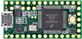
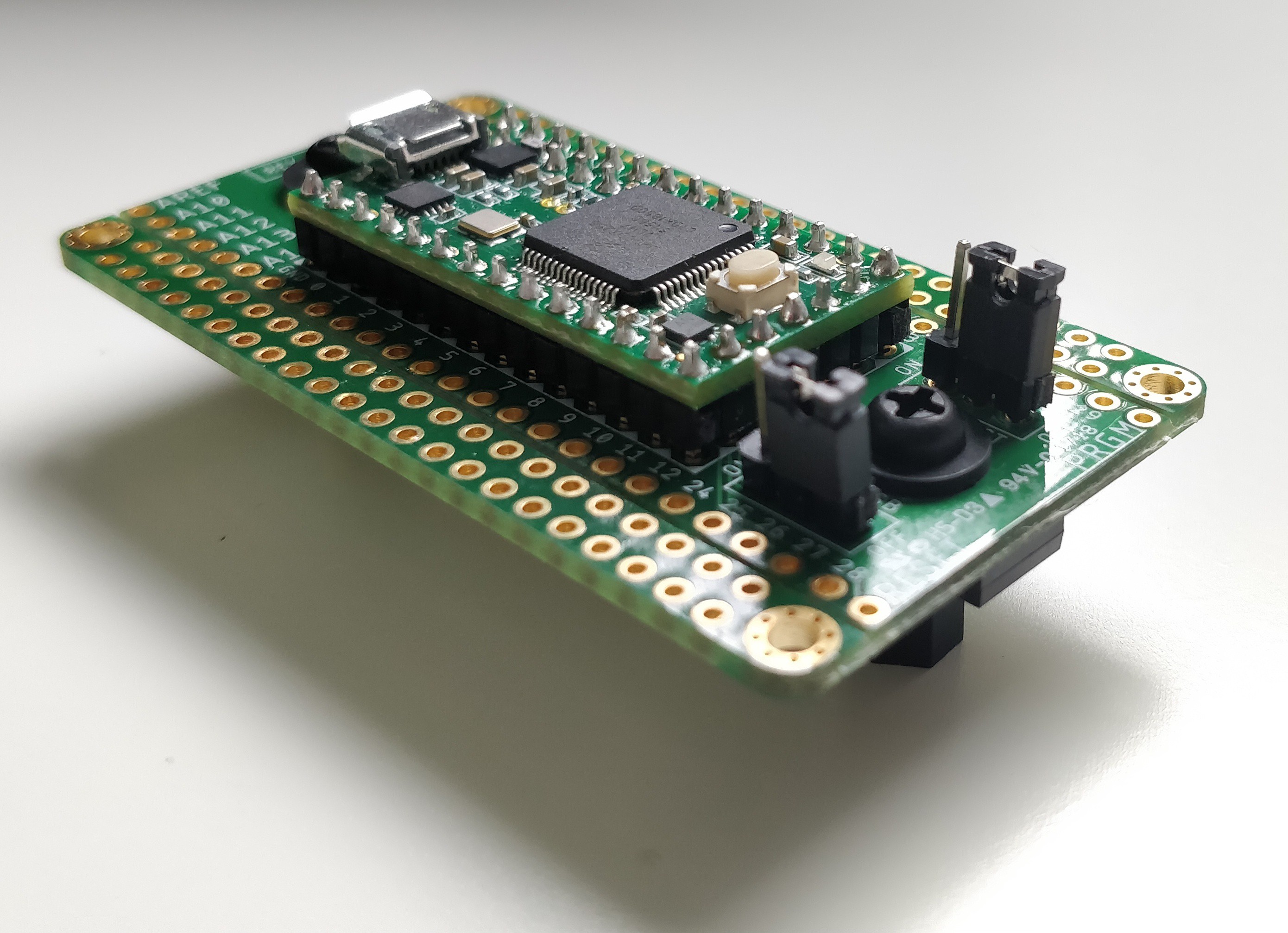
- Based on the Teensy 3.2 microcontroller
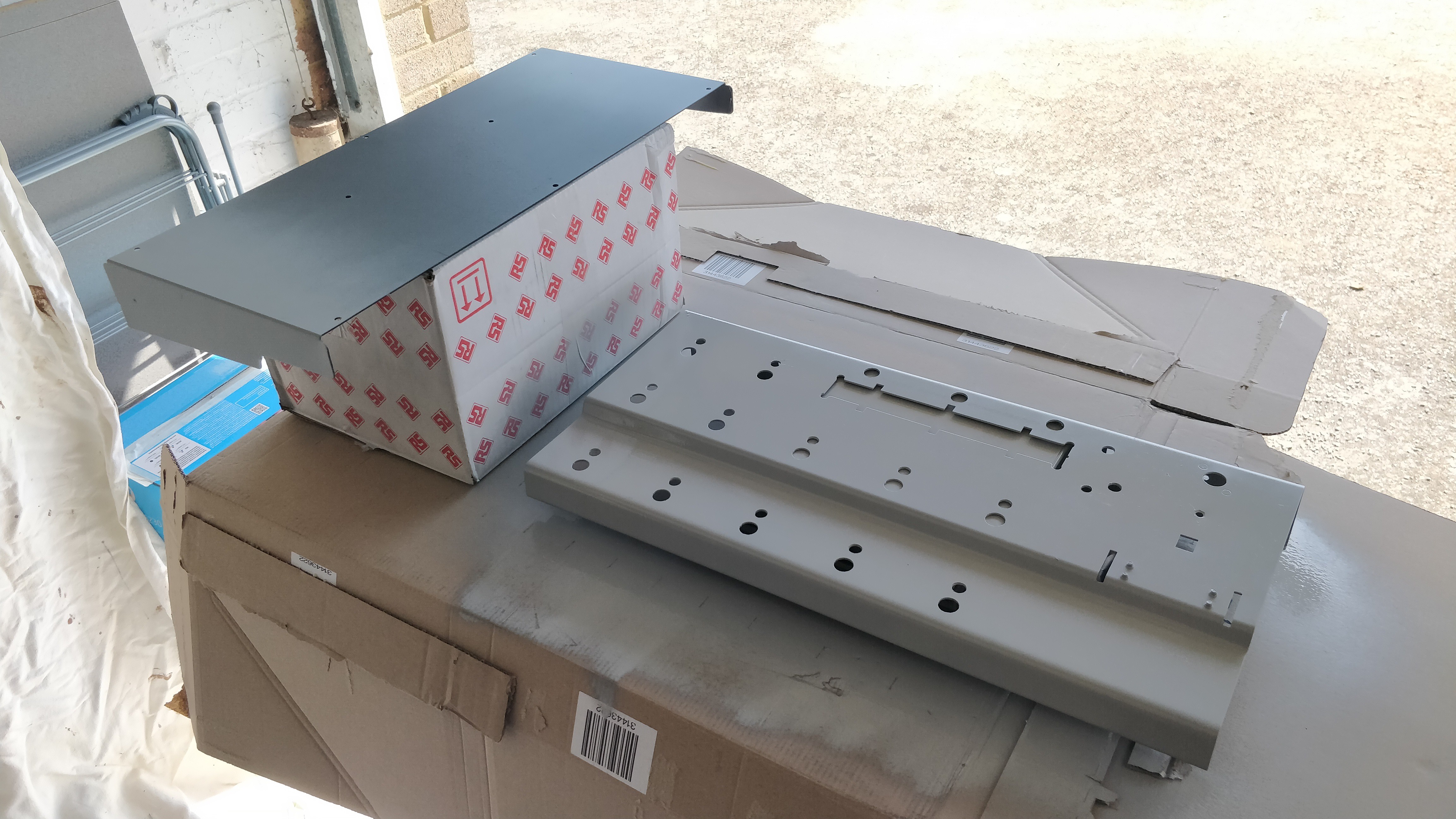
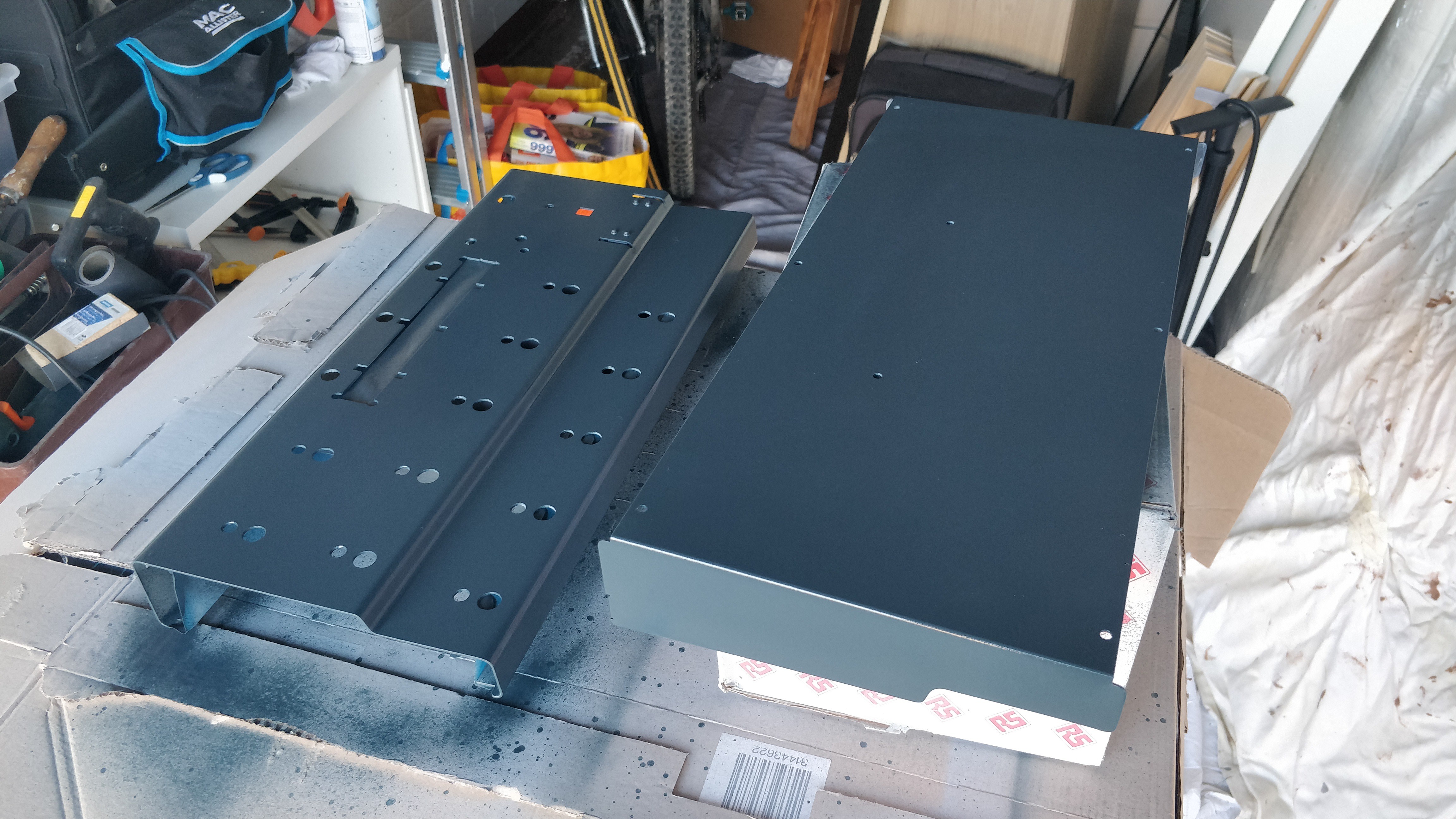
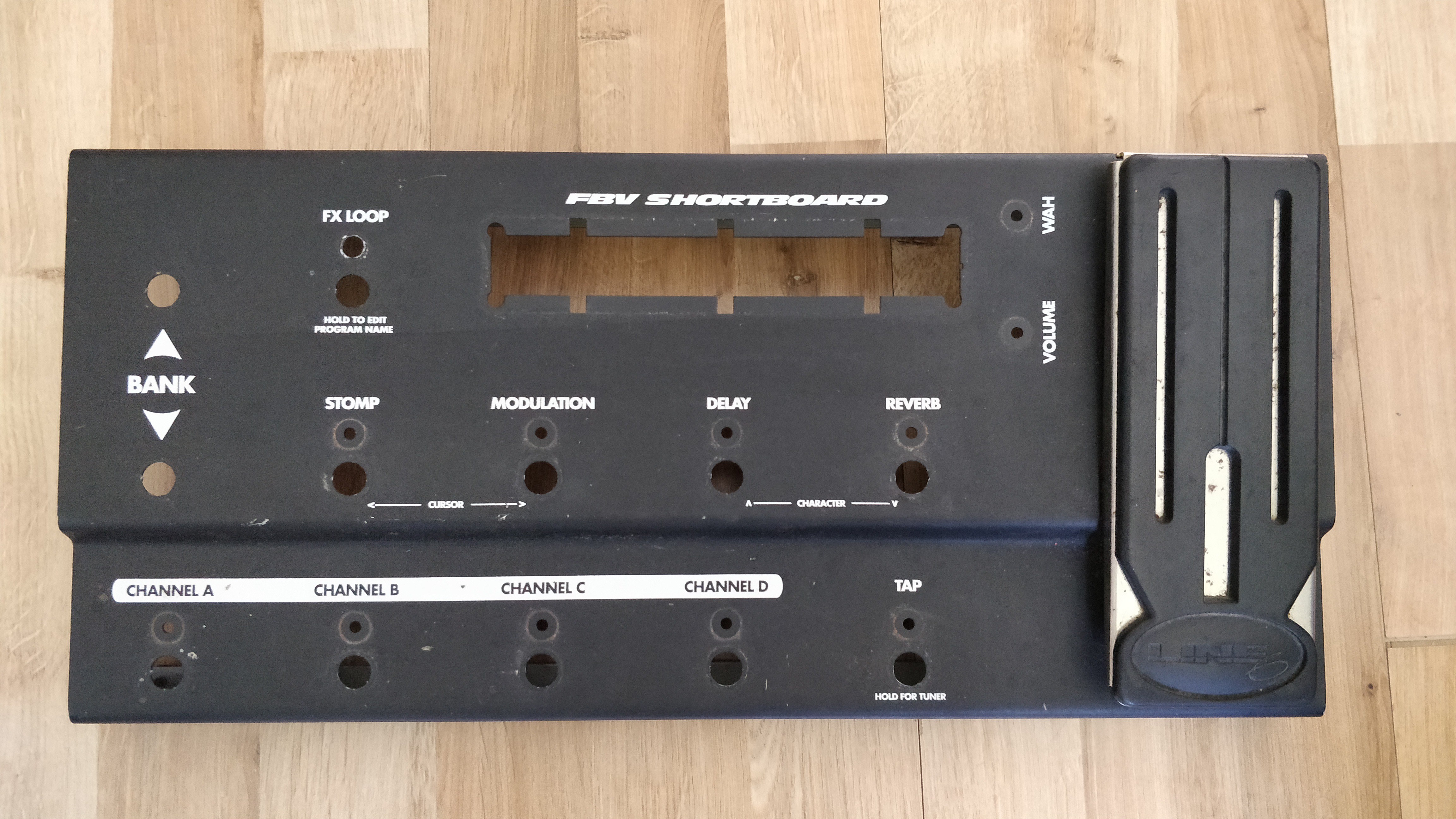
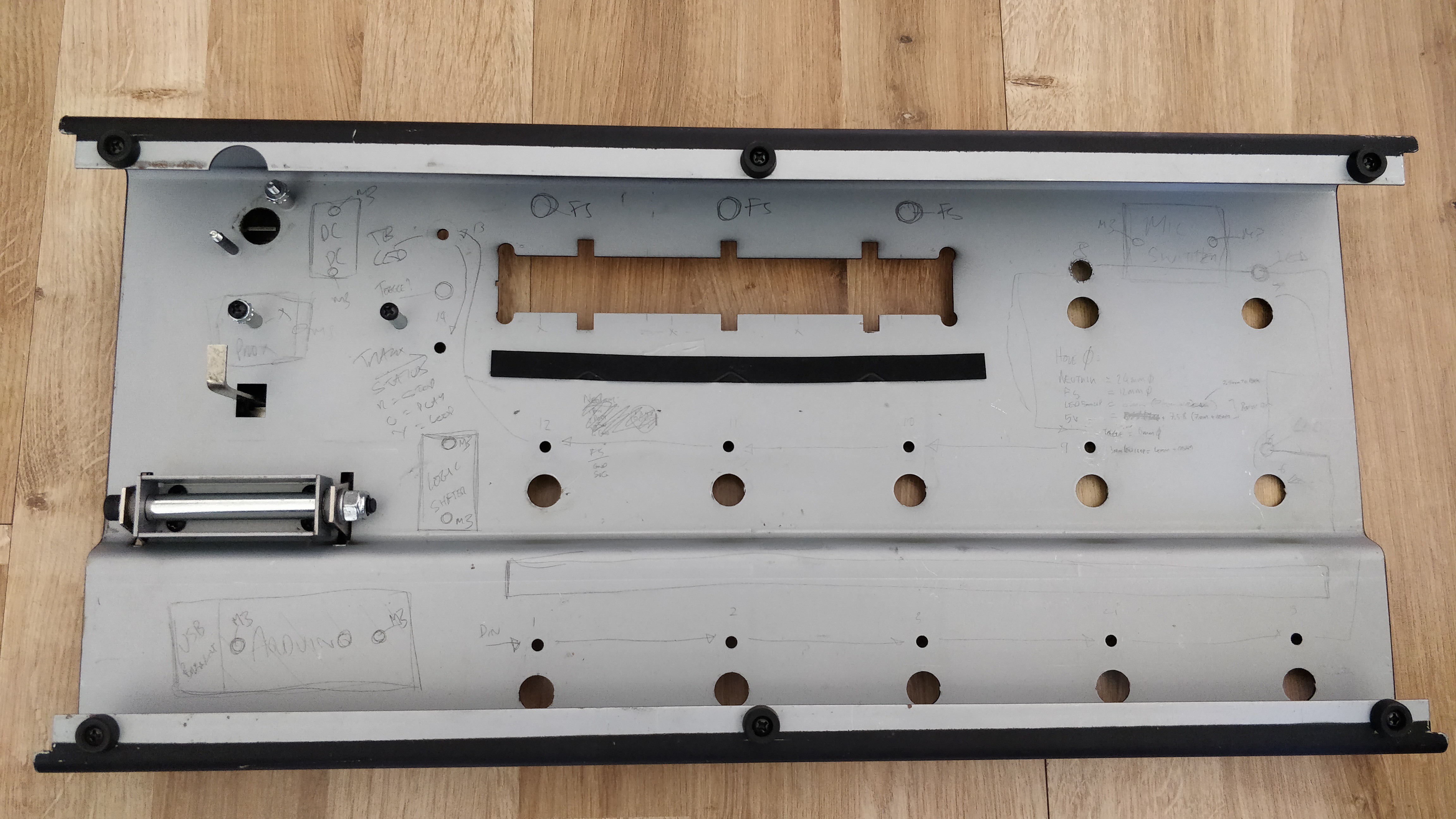
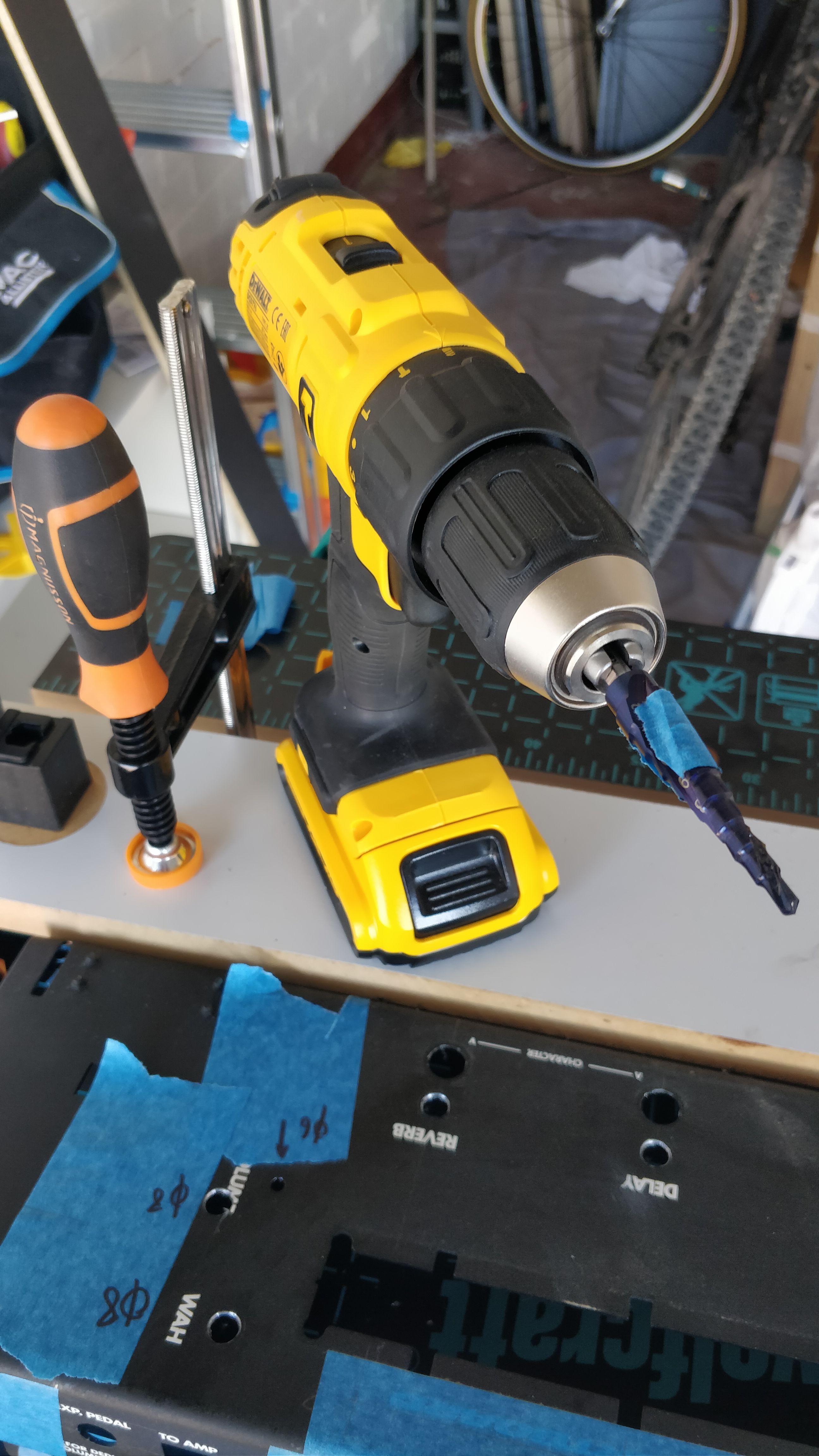
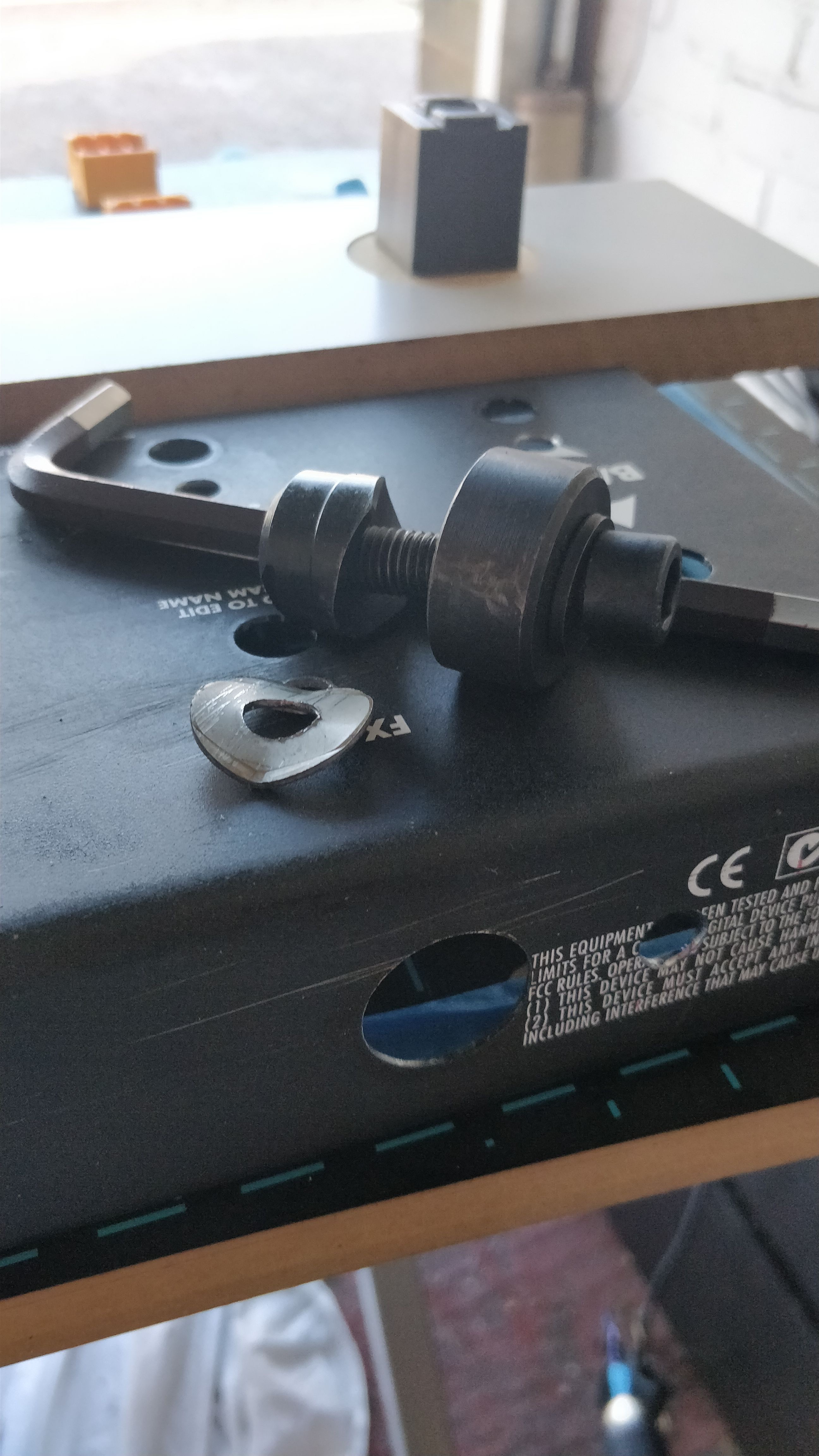
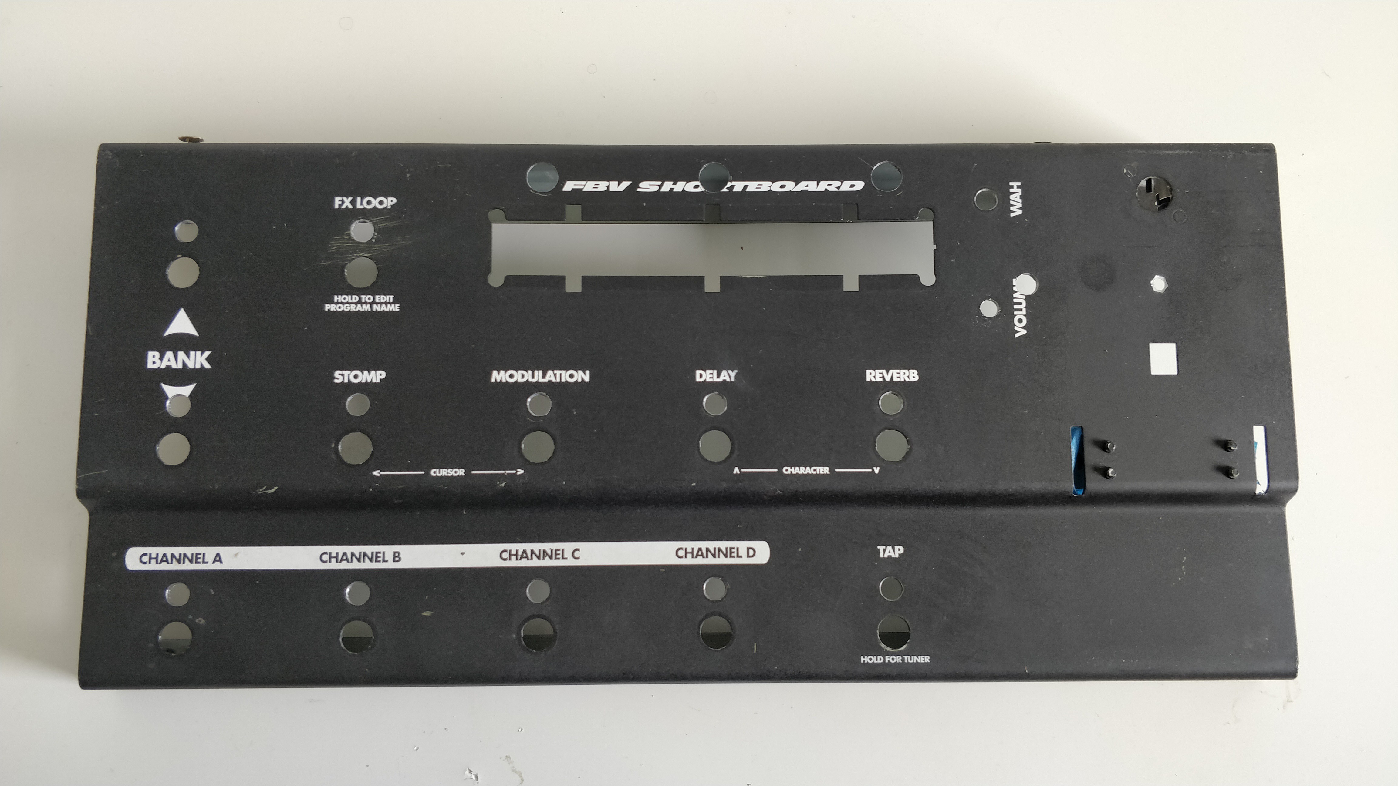
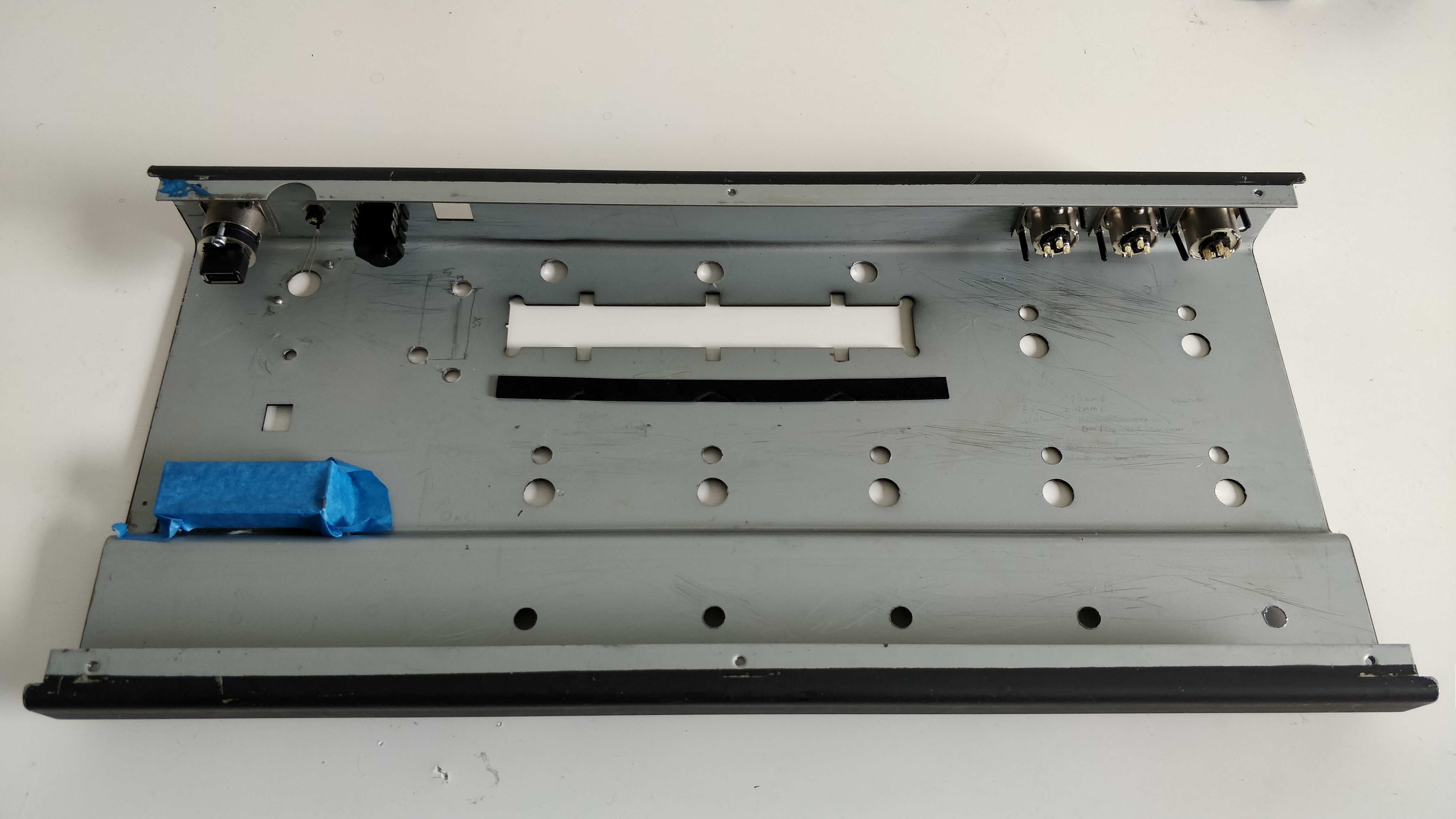
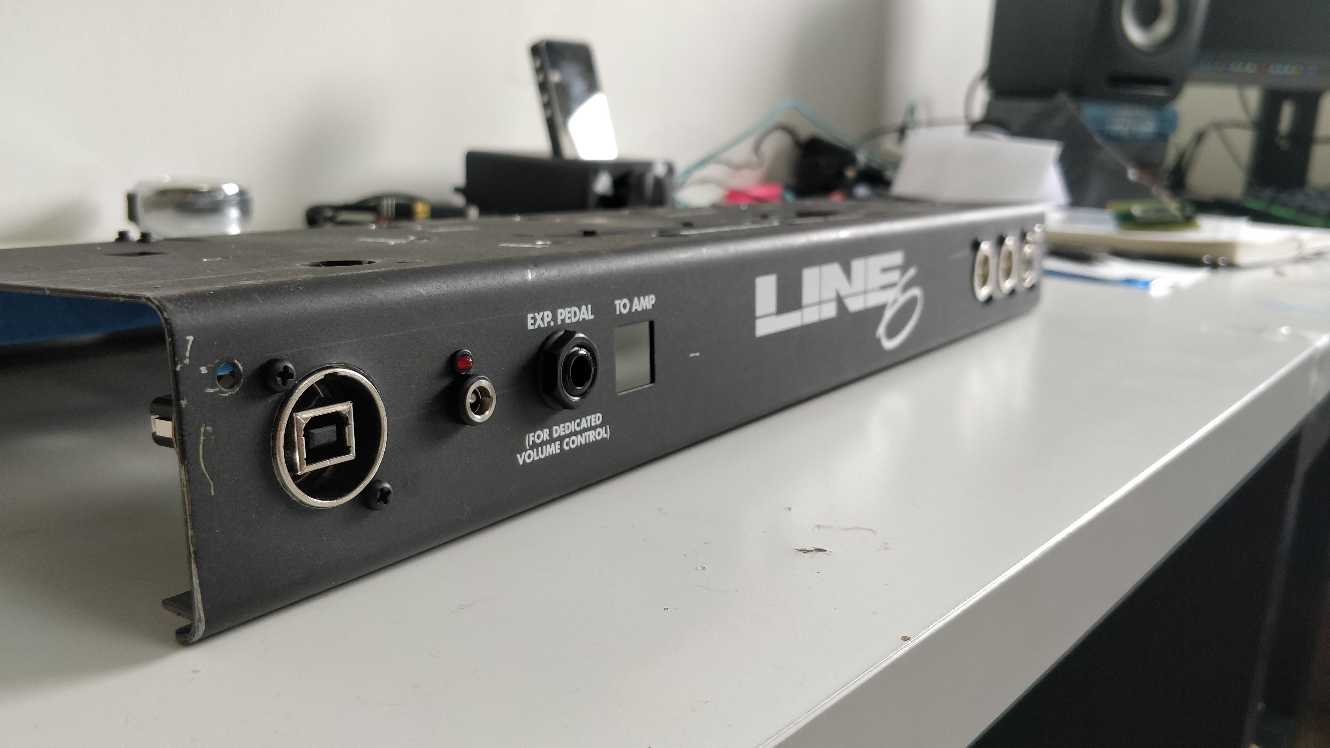
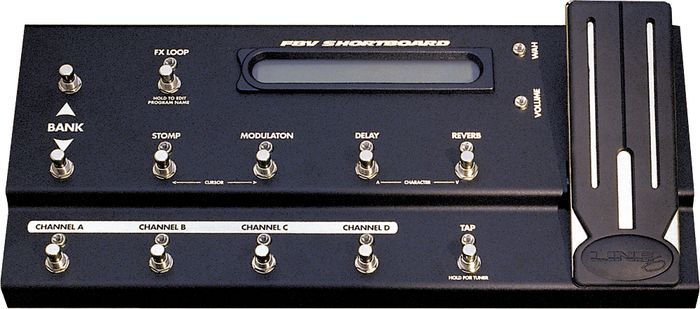
- Housed in a 'reclaimed' Line 6 FBV Shortboard chassis
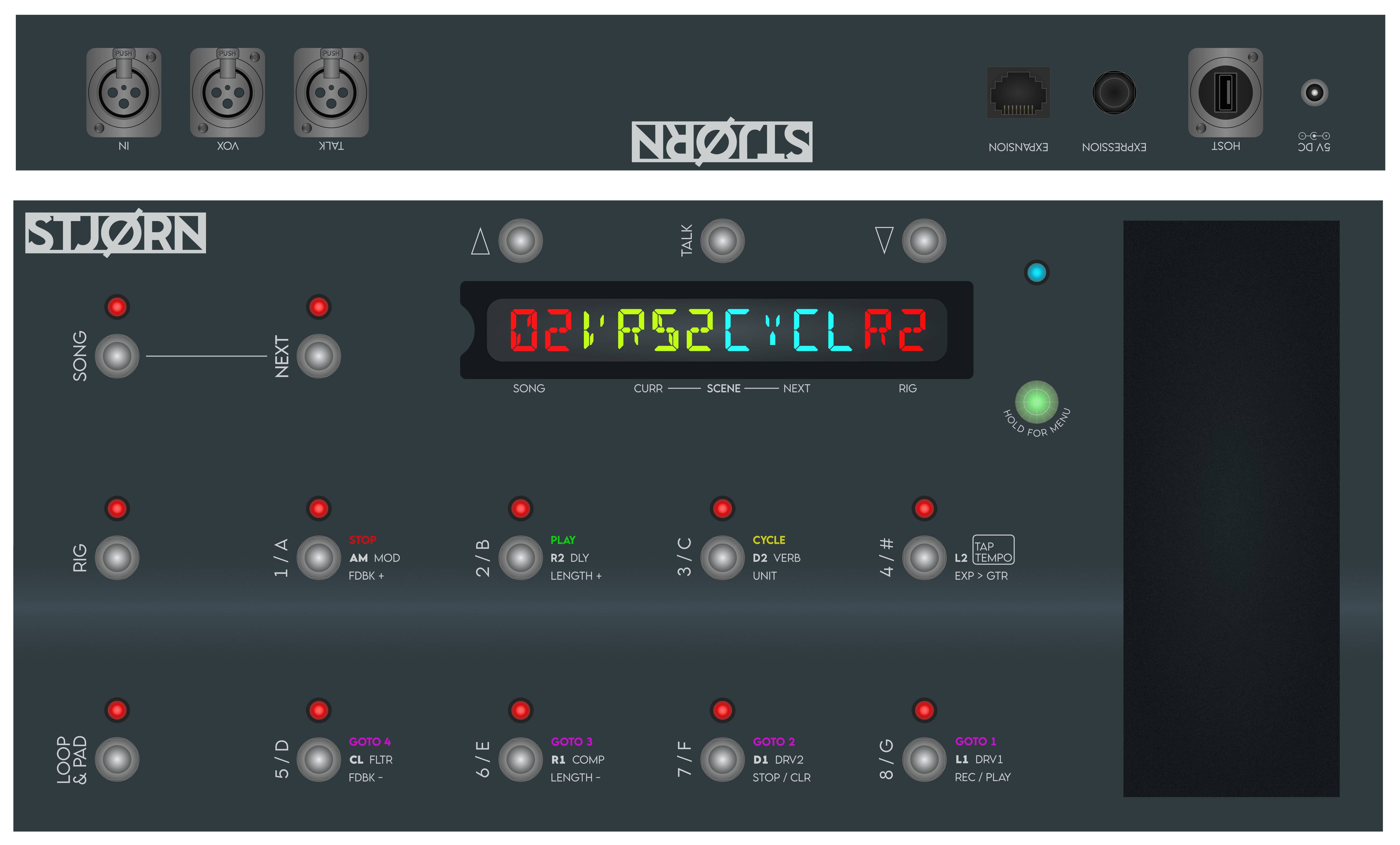
- Three 'modes' of operation
- Song > Control of Ableton Live and/or Loop Community Prime for control of tracks and clicks
- Rig > Control of Gig Performer for switching VST based guitar amp/FX modelling patches
- Looper & Pads > Control of a live looper - using Ableton's Looper - as well as triggering of soft-synth pads in any key
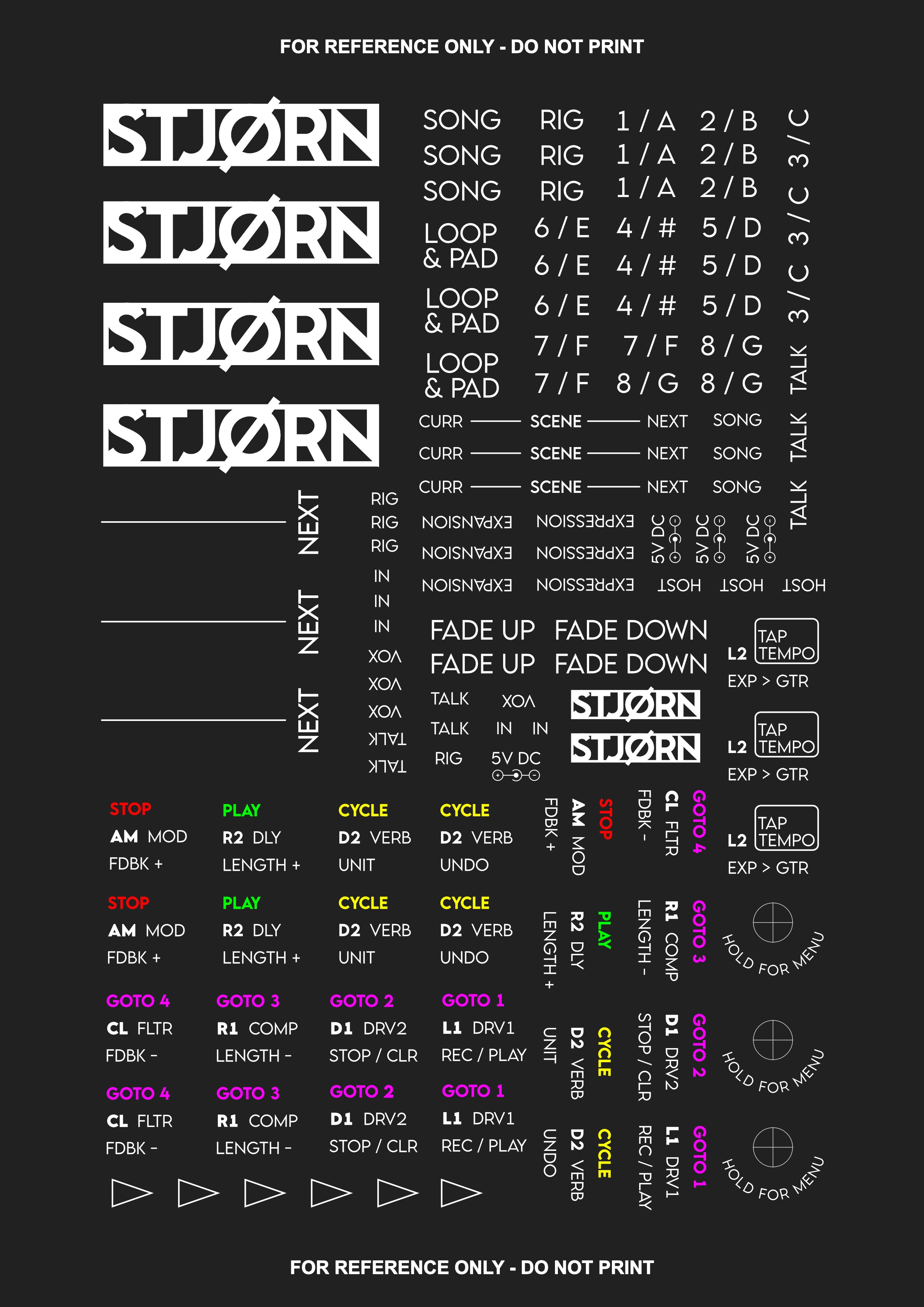
- 8 assignable soft-click footswitches per mode
- Depending on the mode, footswitches have access to short, long, and double press as required
- RGB LED per footswitch to show current state
- Quick access 'next song' button
- Bright, clear, 14-segment based LED screen for display of song, rig, and tracks info
- Built in expression pedal
- Expression pedal changes control output depending on mode, e.g. in Rig it controls a virtual volume pedal in the Gig Performer rig, in Song it controls tracks volume, etc
- USB MIDI connection to host computer
- to communicate with Ableton Live (including custom MAX for Live patches), Gig Performer, and Lemur and OnSong on iPad via Bluetooth MIDI or WiFi OSC (both hosted on computer)
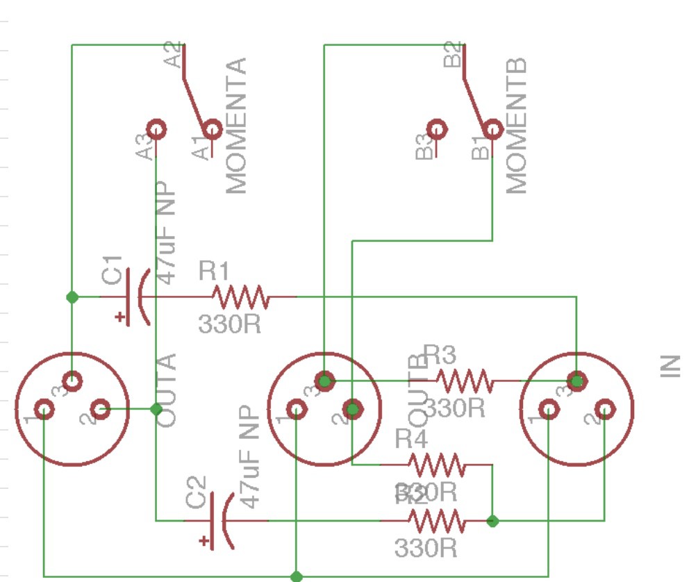
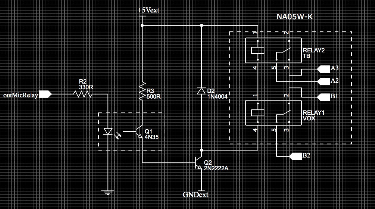
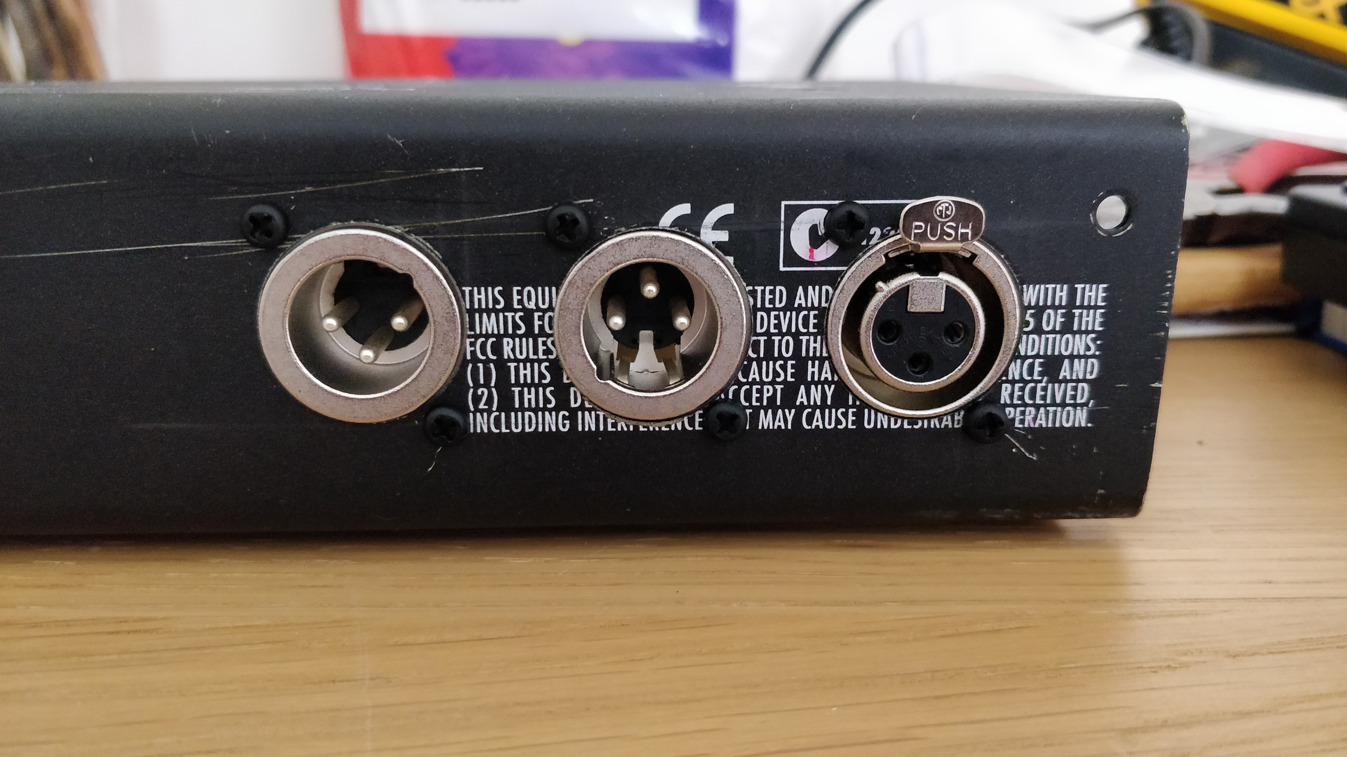
- Built-in, relay based microphone switcher
- For use of a single microphone to feed both front of house vocals and band talkback
- Relay based switching allows footswitch to also trigger other actions if required, or for an external controller to trigger the mic switcher
- 2 additional soft-click footswitches for control of OnSong (iPad based chord chart app)
- External expression pedal input for additional control
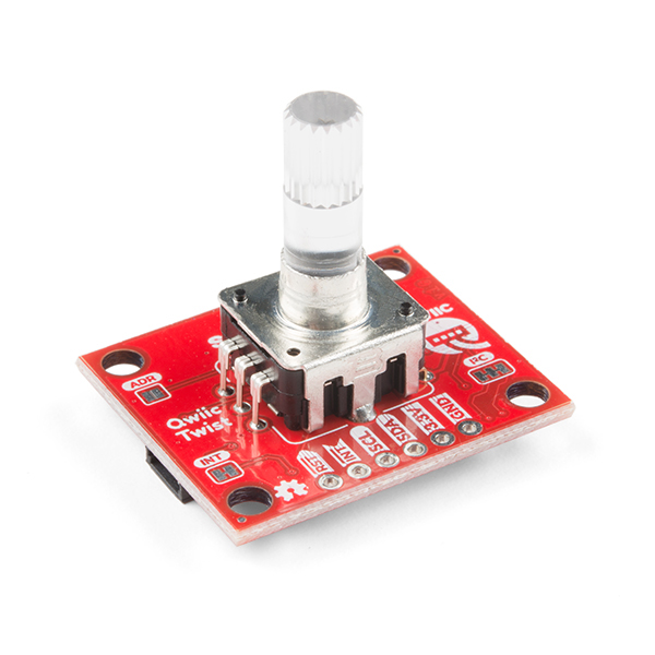
- 'Expansion' port based on i2c using Sparkfun Qwiic differential connector
- This will allow future expansions such as a hardware FX switcher, additional footswitches, remote screens, etc


 Albert Gonzalez
 Quinn
Quinn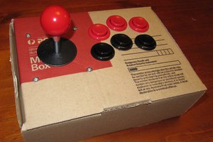
 Robbo
Robbo
 DigiGram