 Bud Bennett
Overview:
This is what this UPS must do:
- Communicate to the Pi the battery chemistry used and the charging status (Charging or Fault). This is a must for this application, where multiple chemistries are allowed.
- Provide power to the output ( the Pi power input) when external power is lost by drawing from the battery source.
- Let the Pi know that this has occurred, using a 2-pin I2C interface, so that it can do a proper shutdown at an appropriate time before the battery is exhausted.
- Allow the Raspberry Pi to monitor the state of the battery to decide when to shutdown its power. As a last resort the UPS should notify the Raspberry Pi that the battery is exhausted and that it is shutting off power.
- Accept a shutdown command from the Pi and handshake to confirm the shutdown command was received, and after shutdown is complete, switch the Pi off by disconnecting the power.
- Reconnect the power to the Pi, which causes the Pi to boot, when the external power returns.
- Maintain the battery in good condition near its maximum capacity.
New Stuff:
I was researching battery management ICs when I ran across the LTC4040. It is billed as a "2.5A Battery Backup Power Manager". The similarities between the LTC4040 and the LTC4041 (which I was using for a supercap UPS circuit -- see my other projects) were too much to ignore. I already had several working UPSs using a lithium battery -- why another one?
After spending a bit of time reading and understanding the data sheet I thought that the LTC4040 could add a lot of capability that was missing in the previous design:
- Multi-chemistry charger: capable of charging/maintaining both LiIon and LiFe batteries.
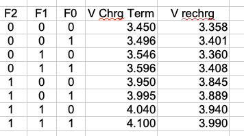
- Programmable charge termination voltage: four programmable termination voltages for each battery chemistry to maximize battery longevity.
- Synchronous buck charger for increased efficiency.
- A safety timer for the charger.
- A temperature sensor to prevent charging outside safe limits.
- A fault indicator for problem batteries.
- Automatic switchover from AC input to battery backup when AC power fails.
- Input current limiting to prevent overloading the AC adapter when charging.
- Potentially lower current drain from the battery in both normal mode and sleep mode.
- Lower component count -- the jury is out on this one. The LTC4040 replaces a $0.60 stand-alone Li battery charger and the Ti boost converter ($2.50). It also simplifies the input switch.
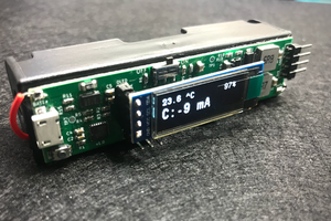
- Lower cost -- OK it's not. The PCB is the same size, and the LTC4040 is about $6, which is more than the cost of the two ICs that it replaces, but you're getting a lot more functionality. I don't know if it's worth it yet. [Edit 2019-03-03: Yeah...it's worth it. The ability to monitor charging and faults via the I2C interface is probably worth a couple extra dollars.]
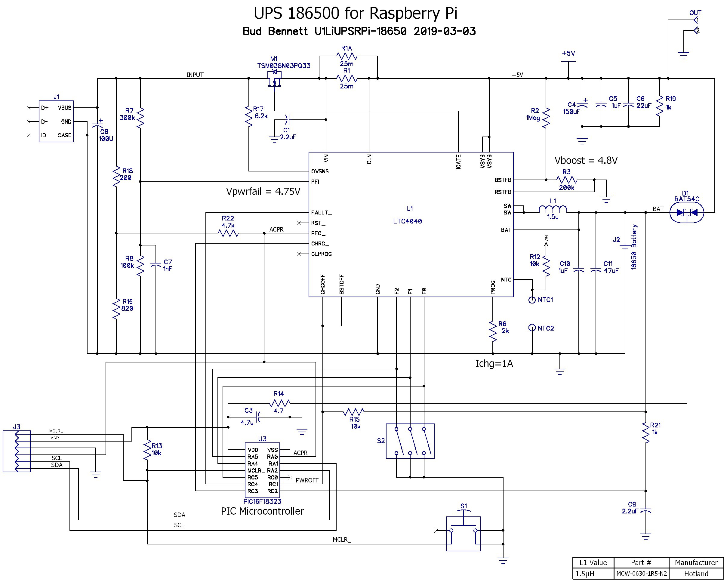
The Current Schematics:
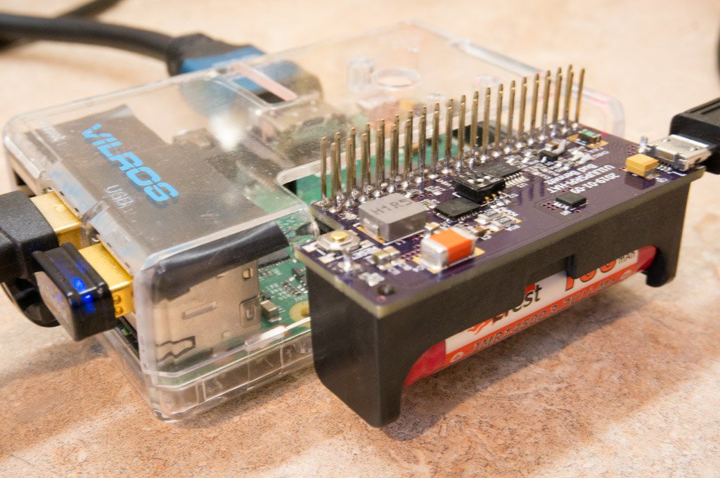
The schematic is not very pretty. That's because the connections of the PIC micro controller were decided by the efficiencies of the layout rather than niceties of the schematic page. There are now two versions -- a "Hat-like" version using a 14500 battery, and a standalone version using an 18650 battery.
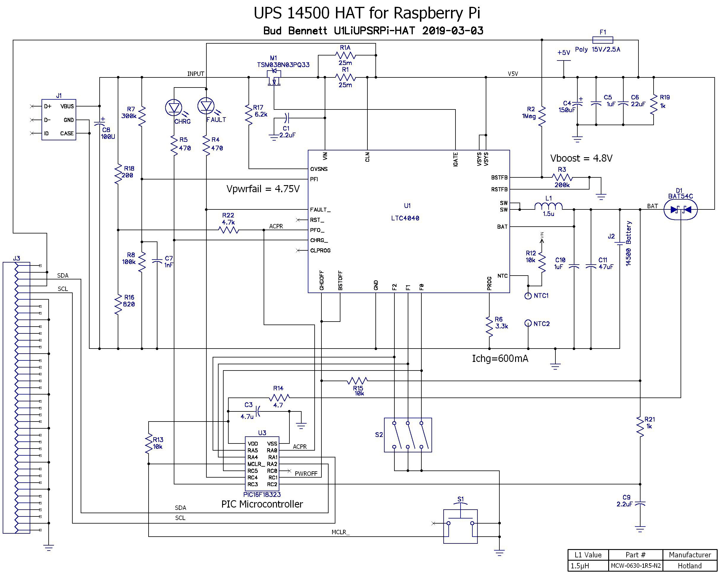
Originally, I was going to use a 3 position DIP switch to program the battery chemistry and the charge termination voltage without the Raspberry Pi being aware of those parameters, since there were not enough pins on the PIC to monitor all of it. The problem with that approach is that the Raspberry Pi, and the PIC, can't know which battery chemistry is being used, and therefore it can't determine when to pull the plug and shutdown the system in order to prevent damage to the battery. I then considered, briefly, allowing the PIC to set the battery chemistry and charging parameters via software. The problem with using software to set the charger parameters is that it is potentially susceptible to being hacked and...
Read more »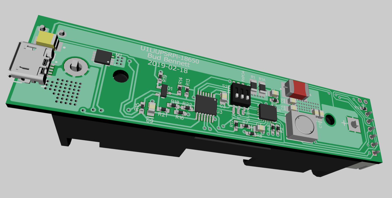
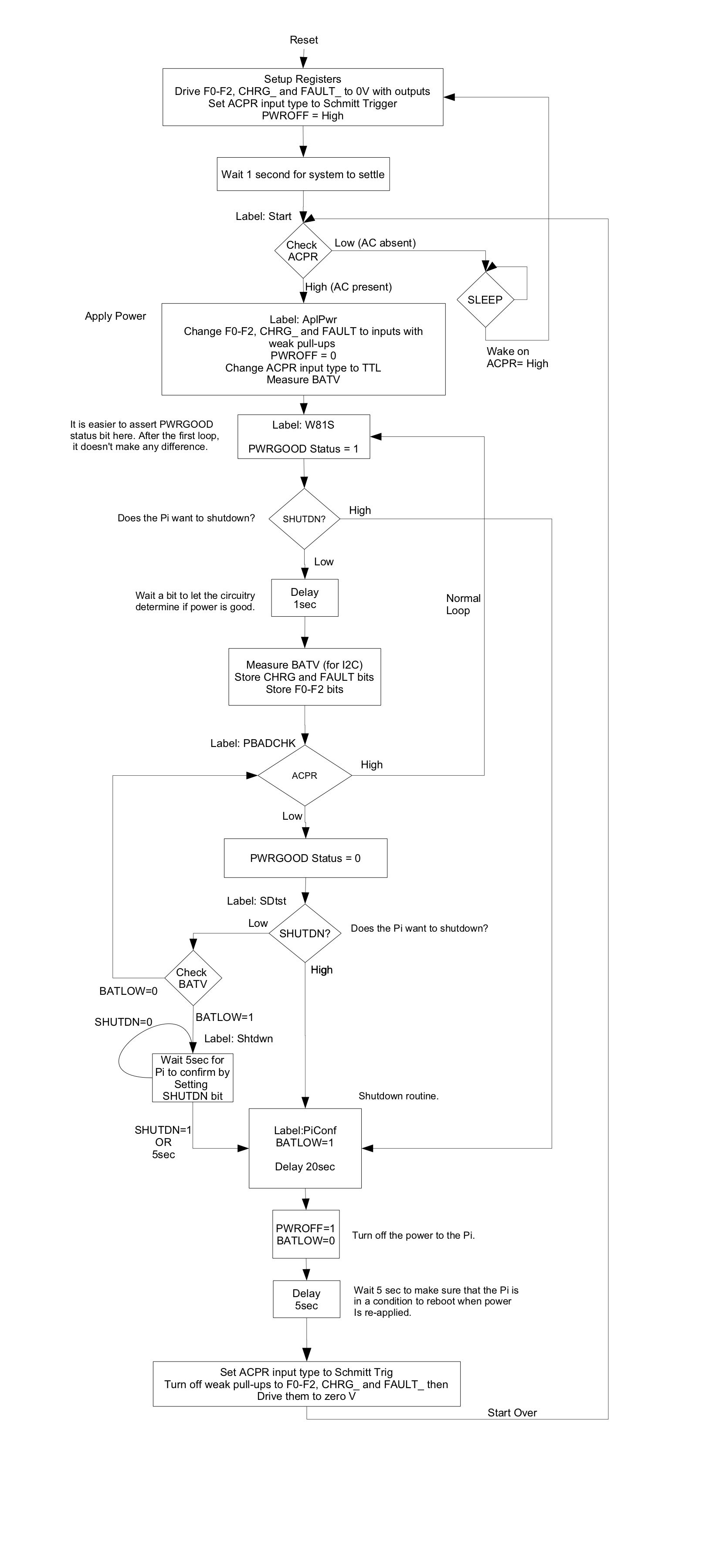 The watchdog timer is disabled. There isn't really anywhere for the program to hang (famous last words.) The only interrupt driven routine is the I2C interface -- and if it hangs then all is lost anyway.
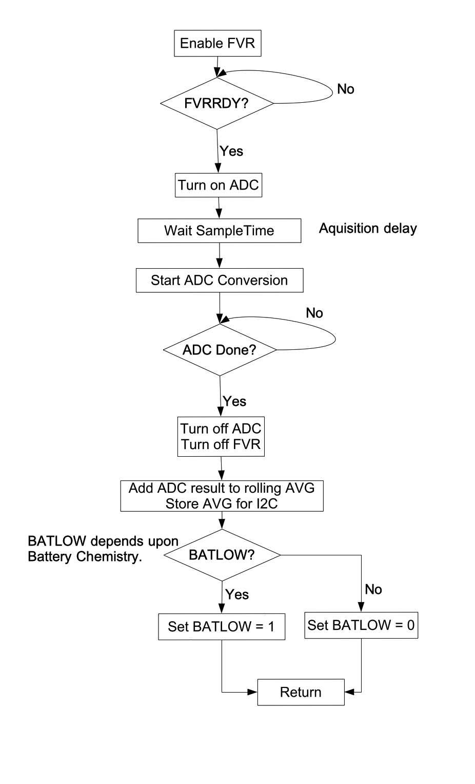
 Manuel Tosone
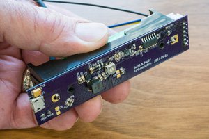

 Manuel Alfonso