 lion mclionhead
The multivibrator affair got the lion kingdom thinking about how to add more states of LED blinking with the same discrete components. The intuitive way is just adding more capacitor/BJT stages to extend the multivibrator to more than 2 LED's. The problem is multivibrators only manage 2 states, no matter how many LEDs they have. You can make a counter by using cascading multivibrators as flip flops, but it's complicated.
The easiest way to do it is by having parallel multivibrators, each operating at powers of 2 speed.
0b00001000
0b00000001
0b00000010
0b00000011
0b00000100
0b00000101
0b00000110
0b00000111
Looking at 9 states in binary, each column oscillates half as fast as the other. Multivibrators can have 1 state be a lot faster than the other, so 1 column can be a reset pulse for 1 row to keep all the others synchronized. The reset pulse grounds the base of 1 transistor in each flip flop to get them to start in the same state.
This 4 bit multivibrator counter could then drive a lookup table made out of BJT AND gates to power the LEDs. It would definitely work, with very careful adjustment of resistances & capacitances. The problem is the huge number of transistors required for the lookup table, 14 in total.
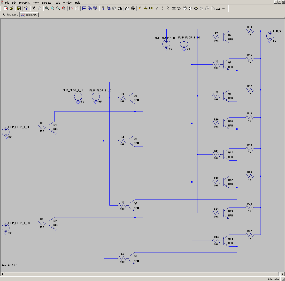
A simple LT Spice simulation proved the 14 transistor lookup table would work, with the 3 flip flops selecting the right LED to light up & 1k's simulating the LEDs. Too bad LT Spice can't simulate a multivibrator or draw blinking LEDs. The total number of transistors for the lookup table & 4 flip flops would be 22 or far less than building a shift register with a clock.
In exchange for the low transistor count, it has a problem with synchronizing the 4 flip flops. There are always going to be glitches when the states change. A 10k & 100uF give around 1Hz for the lowest bit. Getting all the oscillators close enough to minimize the glitches would require 6 expensive multiturn trimpots.
After banging on a simpler solution, the lion kingdom finally figured out how to make a cascading delay circuit using 3 transistors per LED.
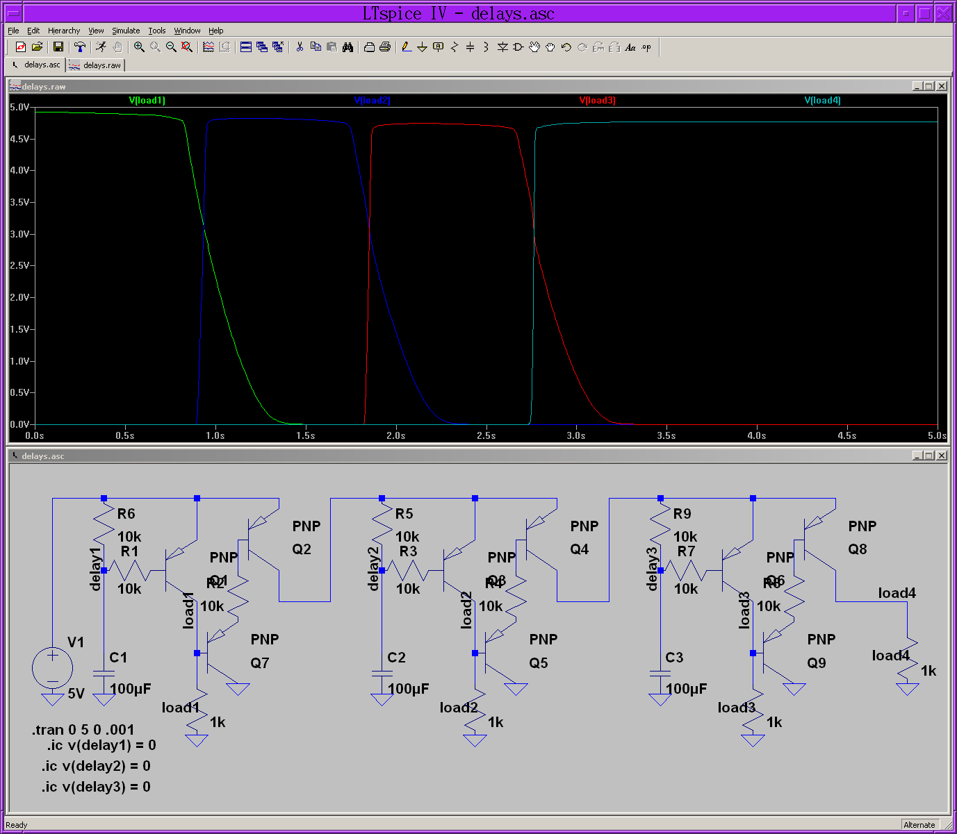
The trick with the cascading delay is we start with load1 on. A capacitor slowly raises the base voltage of the load transistor Q1 until it shuts off. The base current isn't enough to fully quench the transistor, so it needs a pullup R6 but a base resistor R1 is always needed to limit the base current.
With load1 no longer receiving current from Q1, a tiny current from the base of Q7 is now drawn & Q7 turns on. Q7 amplifies the tiny current drawn by the load to turn on Q2 to turn on the next delay circuit. Without the gain of Q7, the load would get too much current & never appear to turn off. The fact that it turns off is only an illusion.
The trick is there's a multivibrator which resets the sequencer by grounding all the delay voltages. The 1st delay circuit doesn't need a capacitor because it's turned on by the reset pulse. A final LED after the last delay circuit doesn't need a delay because it's turned off by the reset pulse.
It would be a lot simpler with FETs, but the lion kingdom wanted lowest common denominator childhood components.
https://www.youtube.com/watch?v=aOfo8UBTknY
The next problem would be what LED pattern to draw. It could be a simple 7 segment display, animal walking, propeller, circle, hourglass. The childhood vision was LEDs side by side. It would be pointless, but nothing in this project has any point.
Discussions
Become a Hackaday.io Member
Create an account to leave a comment. Already have an account? Log In.