 Alexander
I worked with such a BMS in my project and realized that there is little information about it on the net.
This is where I collect my work experience.
If you have researched the issue, write to me and we will publish it in the community.
In this project, I collect any information about BMS that is compatible with the JBDTool program.
Already have an account? Log in.
To make the experience fit your profile, pick a username and tell us what interests you.
I worked with such a BMS in my project and realized that there is little information about it on the net.
This is where I collect my work experience.
If you have researched the issue, write to me and we will publish it in the community.
LH_SP10S006 20180612-1.hexBasic firmware for BMS (you need bootloader firmware to flash the cleaned chip). How to change the main firmware see https://hackaday.io/project/162806-jbd-bms-protocol/log/164283-change-of-firmware.hex - 62.11 kB - 06/04/2019 at 08:23 |
|
|
USB_TO_SERIAL_driver.zipWindows driver for working with serial port.x-zip-compressed - 2.17 MB - 12/14/2018 at 10:16 |
|
|
|
Adobe Portable Document Format - 635.63 kB - 12/14/2018 at 09:43 |
|
|
JBDTools V1.6-20170622.zipStable program for Windowsx-zip-compressed - 325.18 kB - 12/14/2018 at 09:43 |
|
|
LH_communication_protocol.xlsxManufacturer Documentation (incomplete)sheet - 33.76 kB - 12/14/2018 at 09:42 |
|
|
I myself have not used this bms with bluetooth. But people write interesting notes about using this tool.
I decided to post these observations here.
Nigel found the default password for working with BMS via bluetooth: 000000.
Standard requests to BMS in the form of a request for basic data, secondary voltage and names in the ASCII line are parsed in the file (from the manufacturer). I will not analyze them. Further, the deals with undocumented features in the form of reading / writing EEPROM.
1. To switch to the EEPROM mode, you need to send the first packet to write to the zero register of the value: 0x56 0x78.
In response, zeros arrive (see figure below).
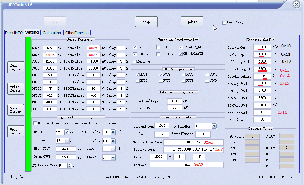
2. Then read (0xA5) registers from 0x10 to 0xA2 and 0xAA.
In figure below shown meaning registers (but I'm not sure about the accuracy of everything).
3. After reading, the write command to the register 0x01.
Without the start packet and the final, an error (0x80) is returned when the configuration registers are requested or changed.
1 BMS stores in memory the fact of errors that can be configured in JBD Tools. It is useful to read them every time you start a device with BMS to analyze past events. After reading them, you need to pack them up so that next time you can only read actual events.
Reading is possible only in EEPROM reading mode (see step 1).
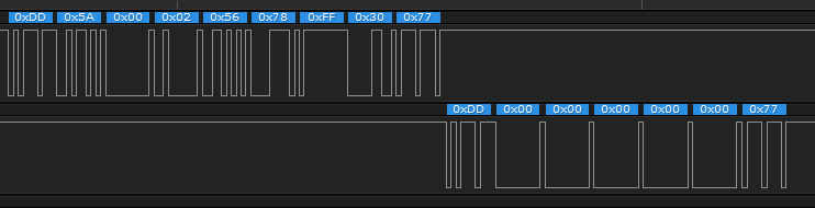
2 The command to read the register 0xDD 0xA5 0xAA 0x00 0xFF 0x56 0x77. Register that stores error counters 0xAA. The table below shows the meaning of each byte in sending a reply from BMS to the request 0xAA. High byte in front.
| Byte in the package | Meaning |
| 4-5 | SC count |
| 6-7 | CHGOC (Charge Over Current) |
| 8-9 | DSGOC (Discharge Over Current) |
| 10-11 | COVP (Cell Over Voltage Protection) |
| 12-13 | CUVP (Cell Under Voltage Protection) |
| 14-15 | CHGOT (Charge Over Temperature) |
| 16-17 | CHGUT (Charge Under Temperature) |
| 18-19 | DSGOT (Discharge Over Temperature) |
| 20-21 | DSGUT (Discharge Under Temperature) |
| 22-23 | POVP (Pack Over Voltage Protection) |
| 24-25 | PUVP (Pack Under Voltage Protection) |
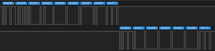
3 Reset errors Error reset occurs by writing to configuration register 0x01. The package: 0xDD 0x5A, 0x01, 0x02, 0x28, 0x28, 0xFF, 0xAD, 0x77.
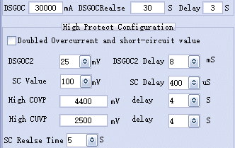
BMS have very interested overcurrent protection.
BMS have three levels overcurrent protection:
- slow protection;
- fast protection;
- short-circuit protection.
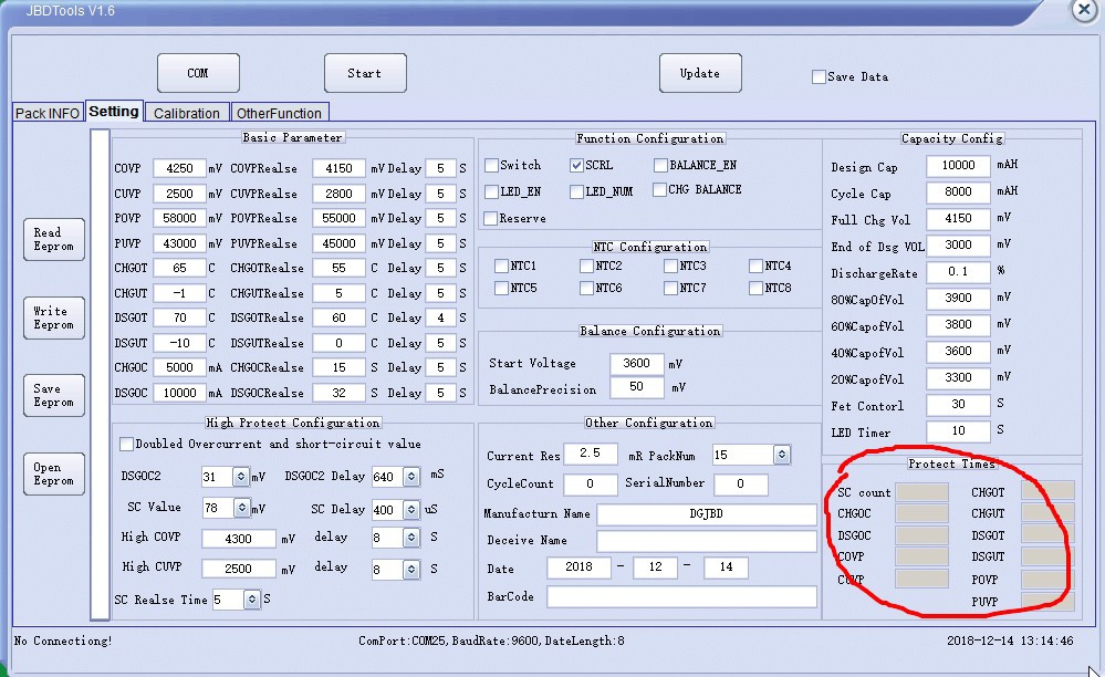
For using this protections checkbox "Doubled Overcurrent and short-circuit value" mast be reset (see below).
So how do you set up all three levels?
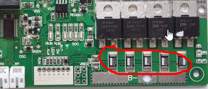
At BMS installed shunts (see below).
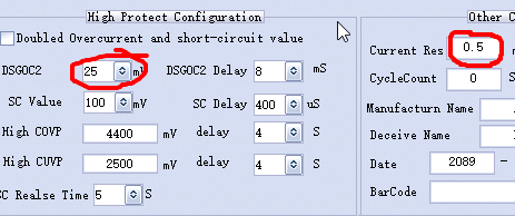
The program window JbdTools necessary to set the resistance of the current-measuring stage. But if you just calculate this resistance formula conductivities addition, it does not mean that you set the correct value of the shunt. In my BMS sets 1 mOhm, but only 0.5 mOhm current calculation is correct.
So you need to:
- set the calculated resistance;
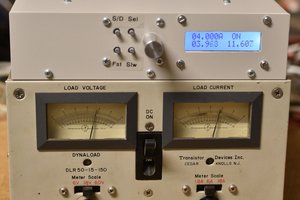
- load the battery for a specific load;
- to adjust the value of the shunt in the program so that the current was determined correctly.
This value must correspond to the maximum current that flows for a long time (> 1 sec). In my case it is 30 A, 3 seconds.
Current value set in the field voltage.
If I want a quick disconnect from the current of 50 A at 8 ms, then I install DSGOC2 I*R = 50 A * 0.0005 Ohm = 25 mV.
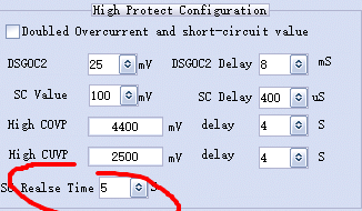
It is short-circuit value (see paragraph 3).
Set the time of the reset of this error (see below).
I measured the currents of the consumption of the BMS itself.
The results are below.
| Mode | Current consumption |
| The load is not connected, the LED on the board is not on. | 70 uA, and every five seconds 150..200 uA |
| The load is not connected, the LED on the board is not on, BMS connected to PC through UART | 100 uA, and every five seconds 200 uA |
| LED on the board is on | 18 mA |
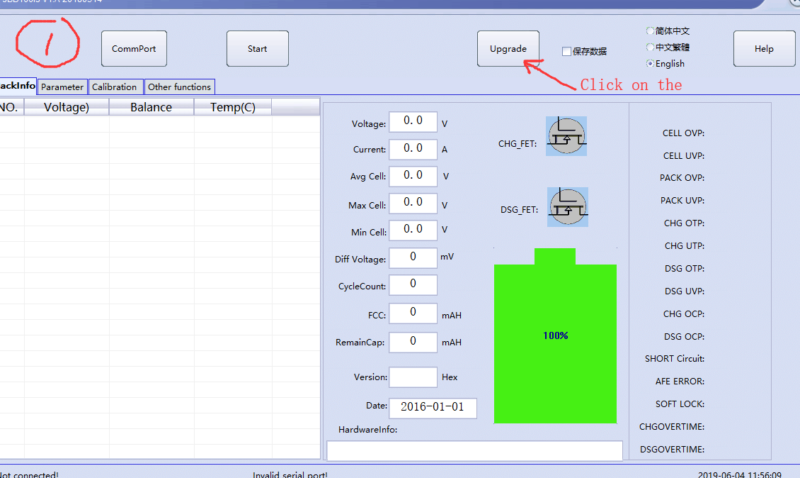
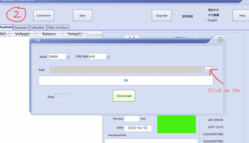
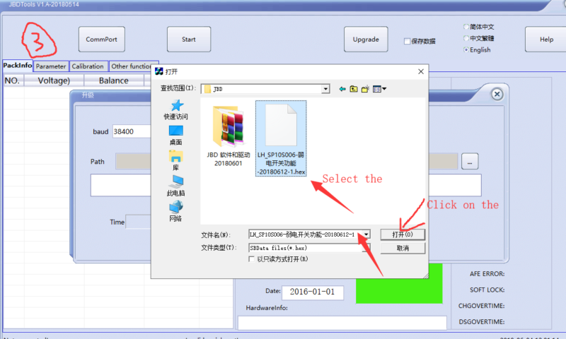
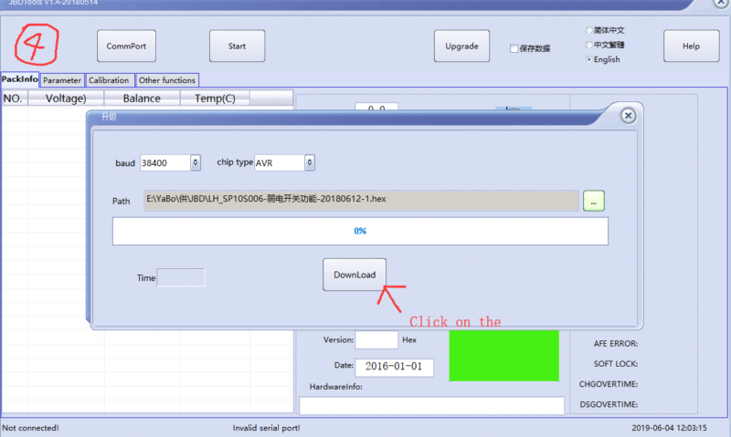
The manufacturer shared the firmware for BMS from 12.06.2018. We really liked this firmware, as it works adequately with the button. The images below show how the firmware changes. Firmware In here.


hello everyone who has firmware from this bms JBD-SP30S005 V1.5

I have issue with my BMS which is 10s SN18210736, when I connect the UART module with my computer and set the com setting and click on start or read EEPROM it does not display anything and just displays 'Reading data . . . .' but a week before it is displaying data and I tried to connect it with esp32 through UART protocol and now it does not display anything. I don't know what's the issue now. Can anybody help me in it?
If the battery is charged properly, after how long does the charging process resume?

Hello
I purchased an BMS controller (JBD-SP30S005 V1.3). Recently, I incorrectly connected the charger (without grounding) when the BMS was connected to the computer's USB. As a result, the computer does not see the USB (the safety resistor on the board is blown out). Can I replace the microcontroller AtMega328p and download the firmware?
Not sure if this is a good idea.
If we have the main firmware, then I don't have the bootloader firmware.
I tried to read the firmware through the dots on the board (MISO, MOSI, SCK), but the firmware is encrypted. So I bricked up one BMS 😞.
Hi! I have the same problem! I tried to update the BMS firmware with your file and it didn't went through, and now the BMS is not working! The BMS is JBD SP155008C, 14S 100 Amps. Can you help me?
Not sure if this is a good idea.
If we have the main firmware, then I don't have the bootloader firmware.I tried to read the firmware through the dots on the board (MISO, MOSI, SCK), but the firmware is encrypted. So I bricked up one BMS 😞.

Hello Friend, pease i need help, i need flash BMS JBD_SP15S020.hex my bms don't work, because I do update to my bms, But I made a flash of another bms LH_SP10S006 20180612-1.hex i find it here
https://hackaday.io/project/162806-jbd-bms-protocol in this page in file
Naw my bms stop working, cannot read the cell voltages, i need flash This BMS, ( JBD-SP15S020 : 30A 48V ), Please Help.
You must contact the seller. My firmware was provided by my seller.
Hello there. This page has been very helpful, thank you! But I have one problem. I updated my bms firmware and now it cannot read the cell voltages. Any idea whats wrong?
Hello, my friend.
Hmm. What is your BMS. What firmware file?
 Bharbour
 Jasper Sikken
Hello, what if you want to connect via RS485 using the TTL to RS485 module?
Please modify the library for RS485 connection