 Ben Peters
Please scroll down to see the project log to see my latest progress. I will provide links to testing videos there.
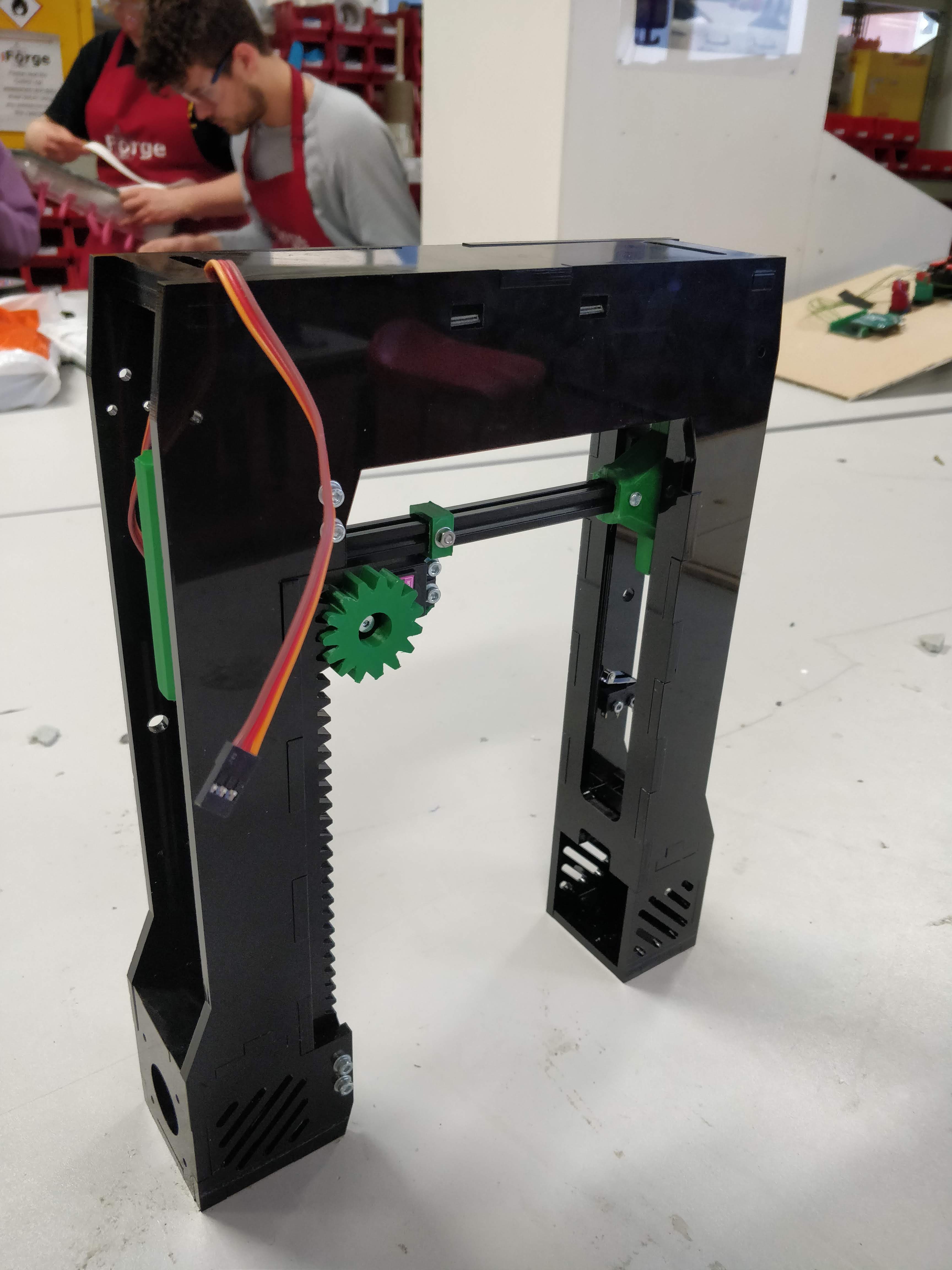
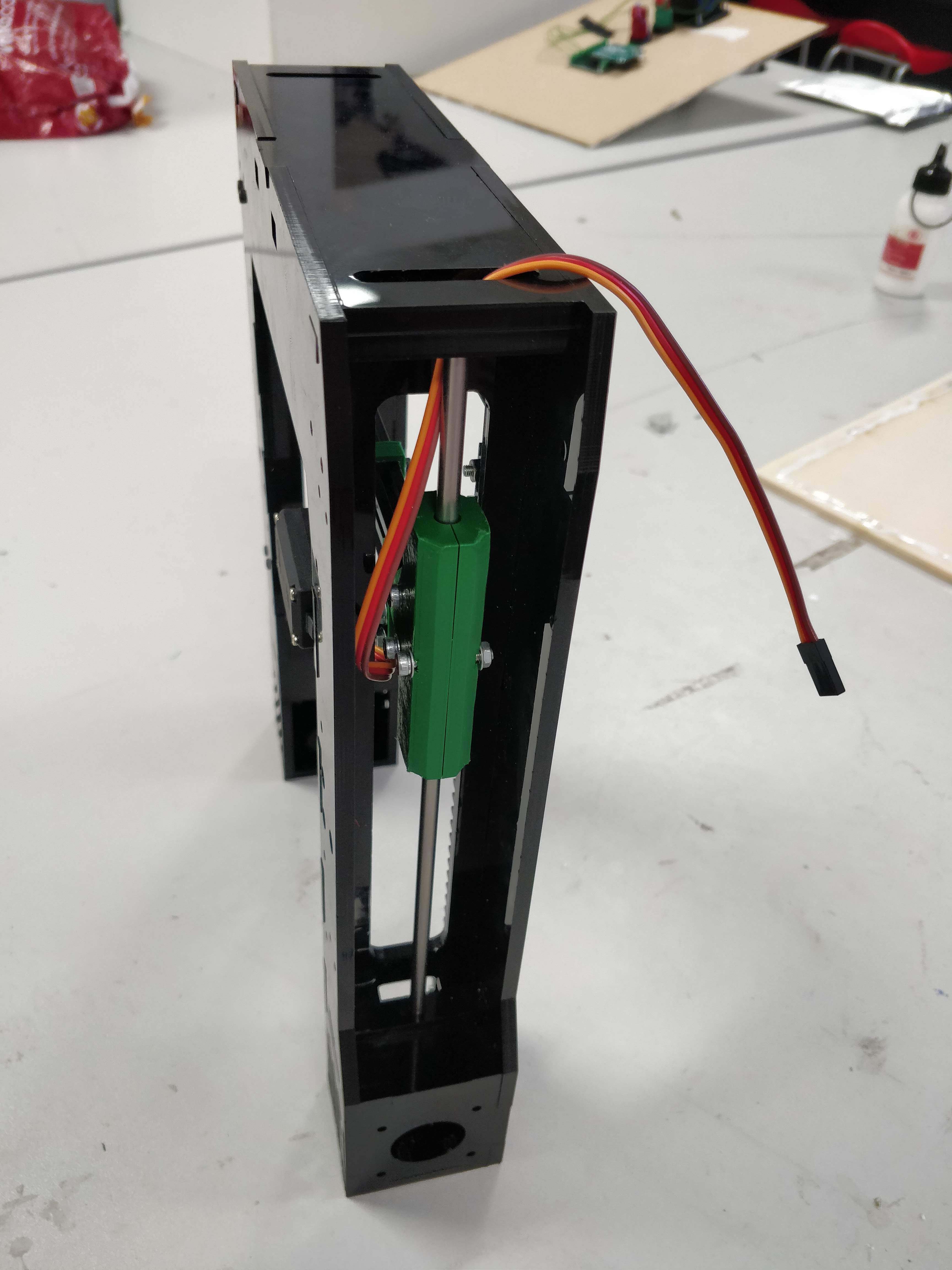
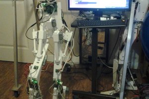
The concept drawing of the robot is the best explaination of what I am trying to build, and why I have called it "Straddle Crane"...
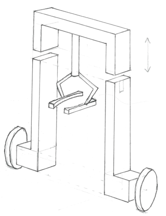
There are 4 key deliverables of this project:
- Build a robot capable of balancing (no position control or crane mechanism)
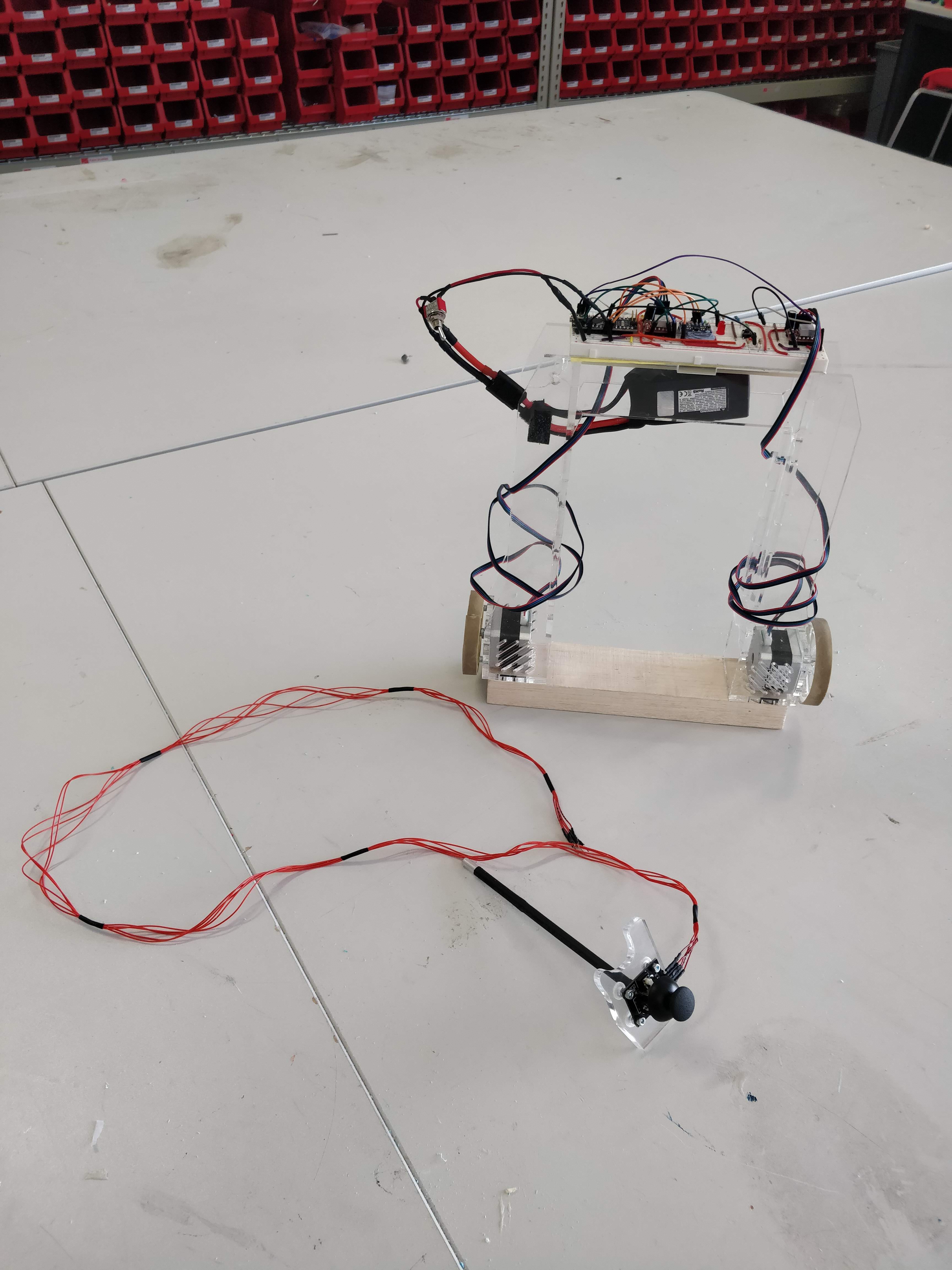
- Develop prototype to be able to move around based on smartphone communication
- Add crane mechanism to robot chassis so that the unloaded crane boom can move and the robot remains balanced
- Develop lifting sequence and successfully pick an object up whilst remaining balanced
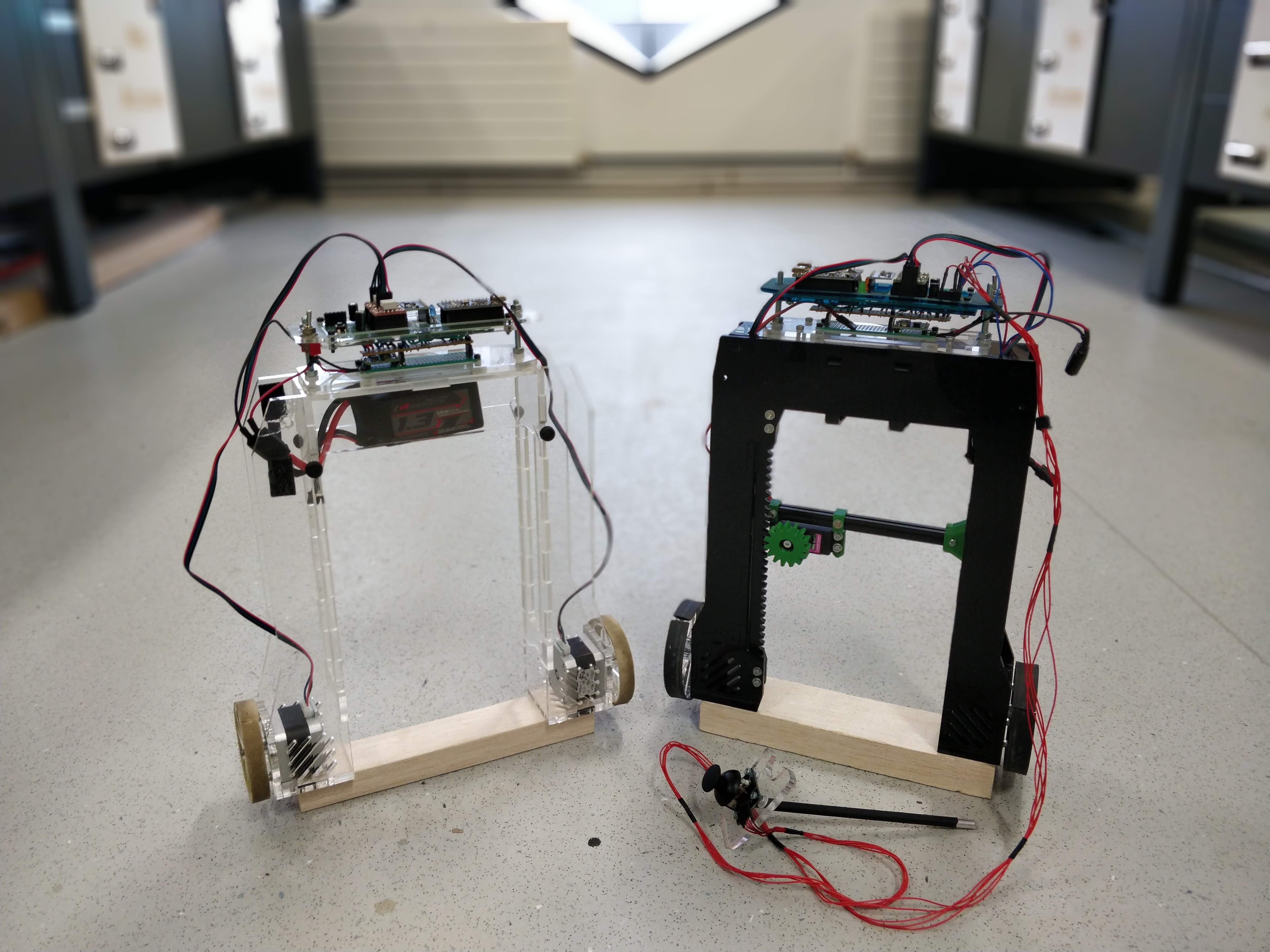
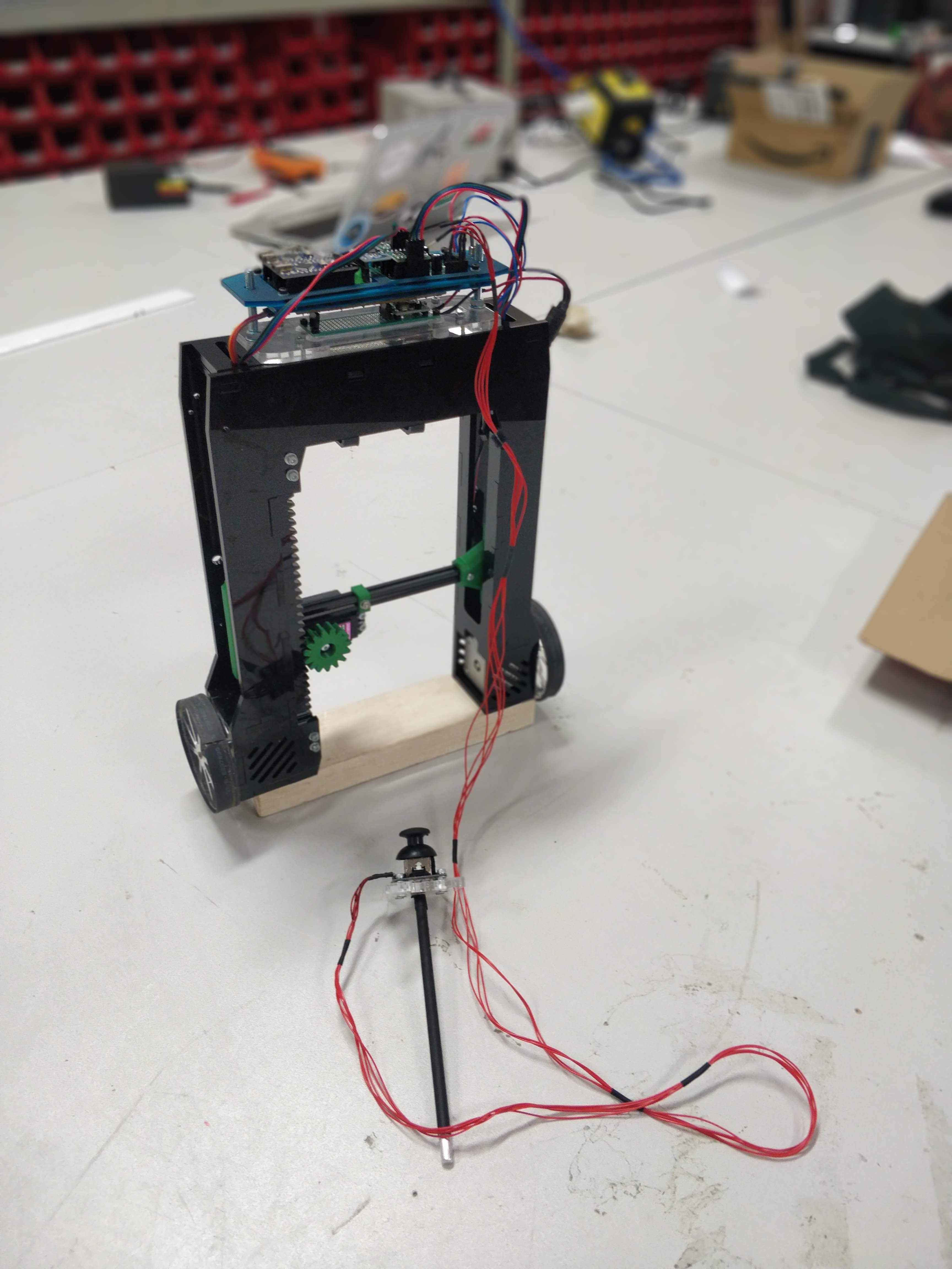
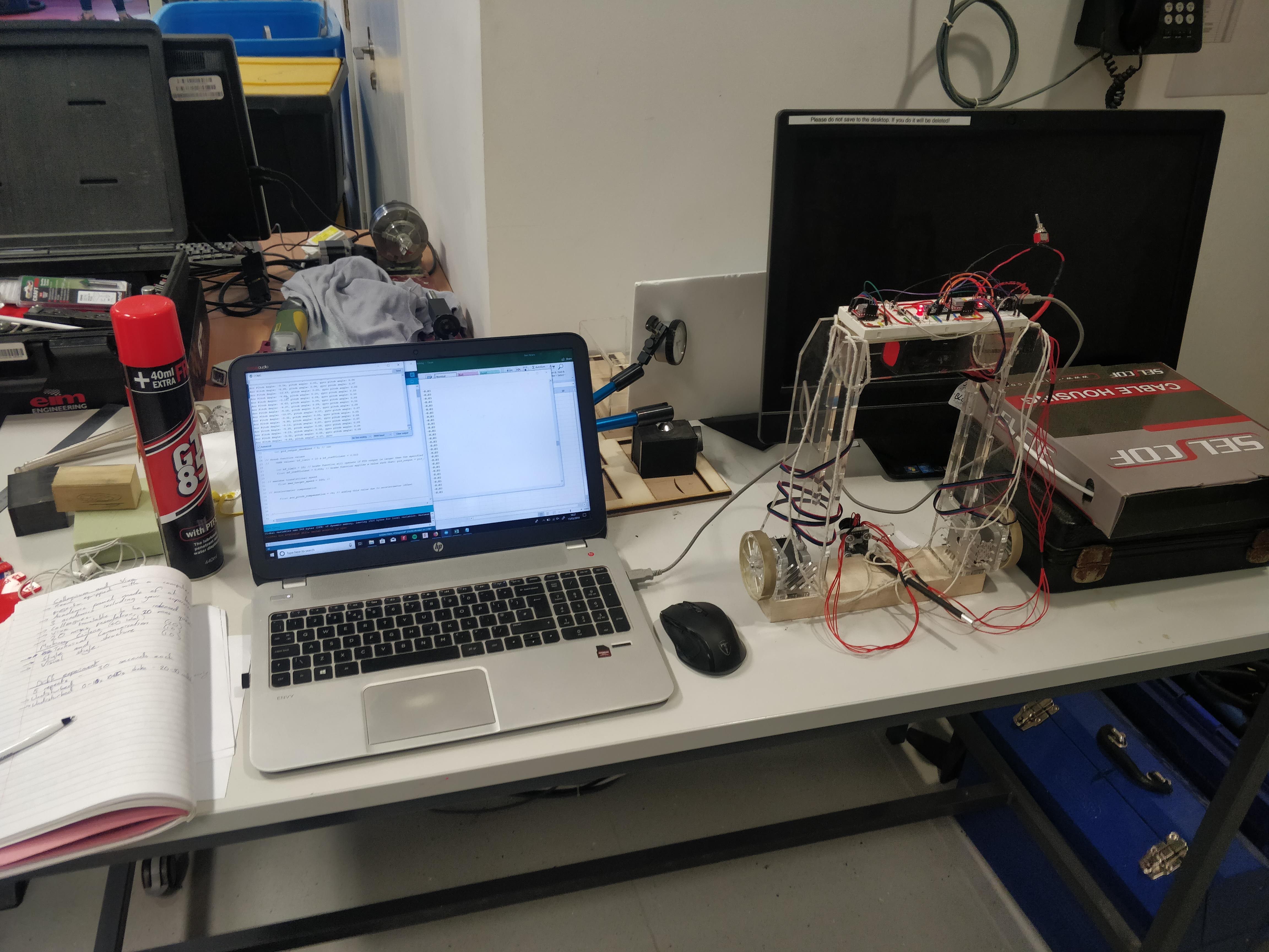
I currently have a prototype that is almost capable of the 1st aim. Here's the link to videos of my intial testing:
As you may can see by some of the videos, the control system needs a bit of development. A common problem is that the robot falls when it reaches equilibrium.


 Ted Huntington
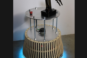
 Will Donaldson
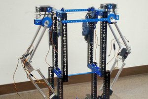
 Avi
Avi 
 Gaultier Lecaillon
Awesome project!
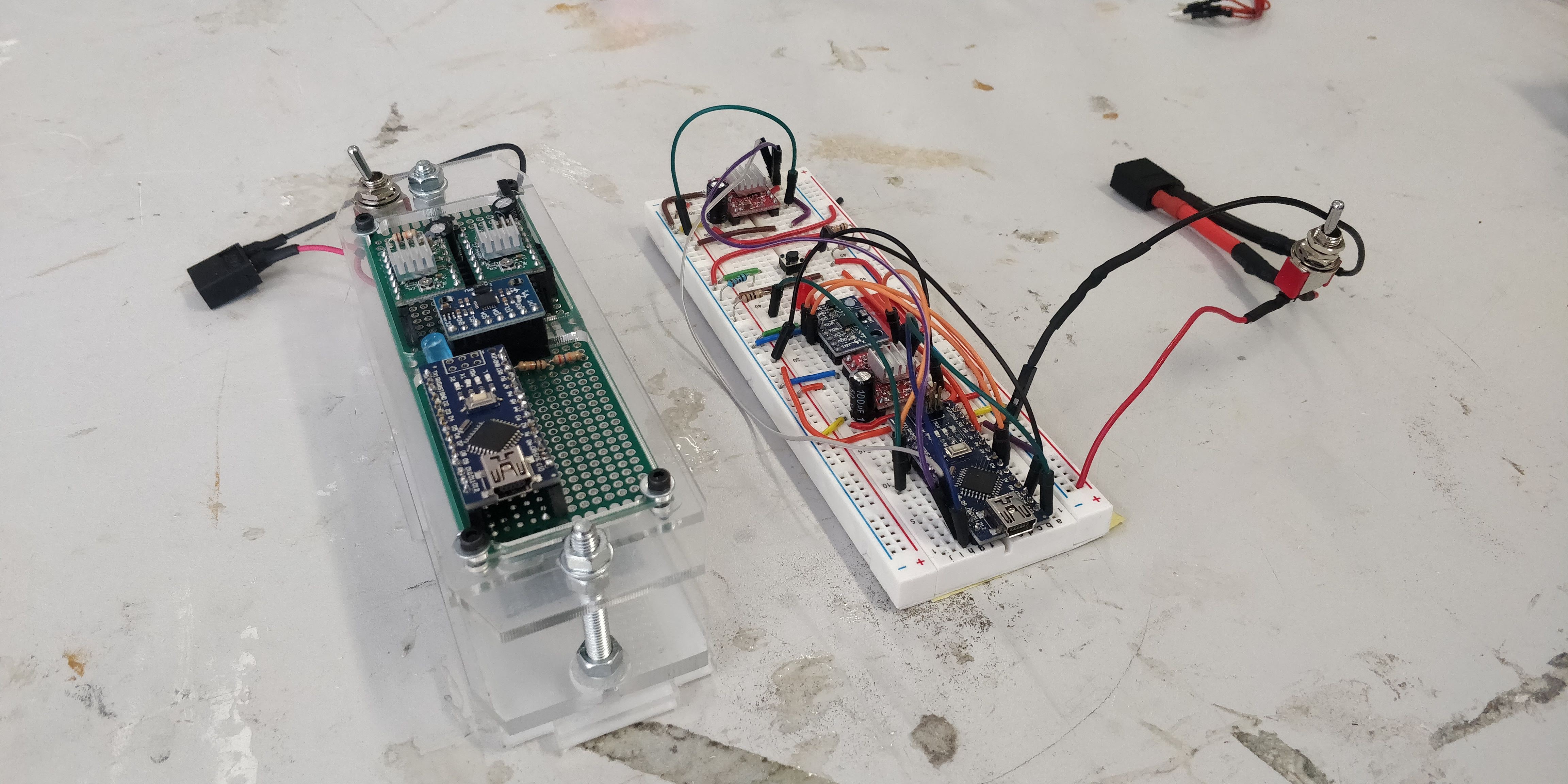
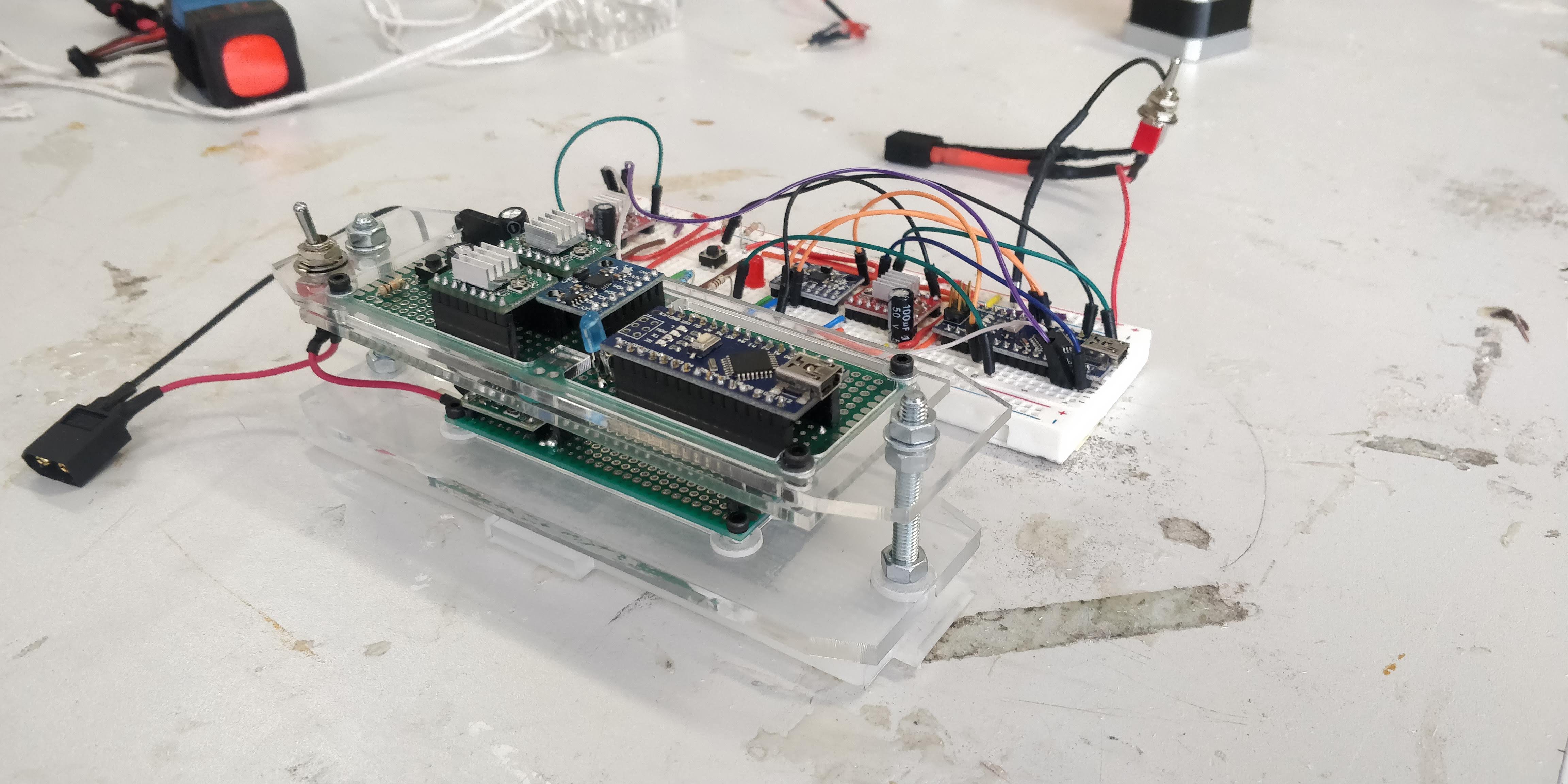
I have a few suggestions. If you find the stepper drivers are getting hot, you could heatsink them, or many stepper drivers will allow external FETs to be used. This would allow significantly more current while spreading the heat load out. Looking at the A4988 datasheet, it looks like using external FETs wouldn't be too difficult.
Also, gyro drift is very common. It is usually characterised in the datasheet. Using the accelerometer data in tandem with the gyro is a good way to improve the drift - if the gyro is changing but the accelerometer isn't showing movement, then you can assume it's drift. This is what "sensor fusion" is all about. Elecia White's book Making Embedded Systems touches on this subject, if I remember correctly. There are many libraries out there for sensor fusion but depending on your timeframe, you can always try writing it yourself! It's a bit of math, but nothing too difficult.
If you have any problems, feel free to message me! I'd be happy to help.
Cheers!