Close
0%
0%

Freeform robot

A simple robot built from wire

Similar projects worth following
This is a tiny robot with chassis made from scrap wire I got from inductors in my parts box. The servo motors are hacked for continuous spinning. An ATmega8 runs Arduino code to control the servos and poll an ultrasonic sensor for obstacle avoiding. I started this project to participate in the Circuit Sculpture Contest.

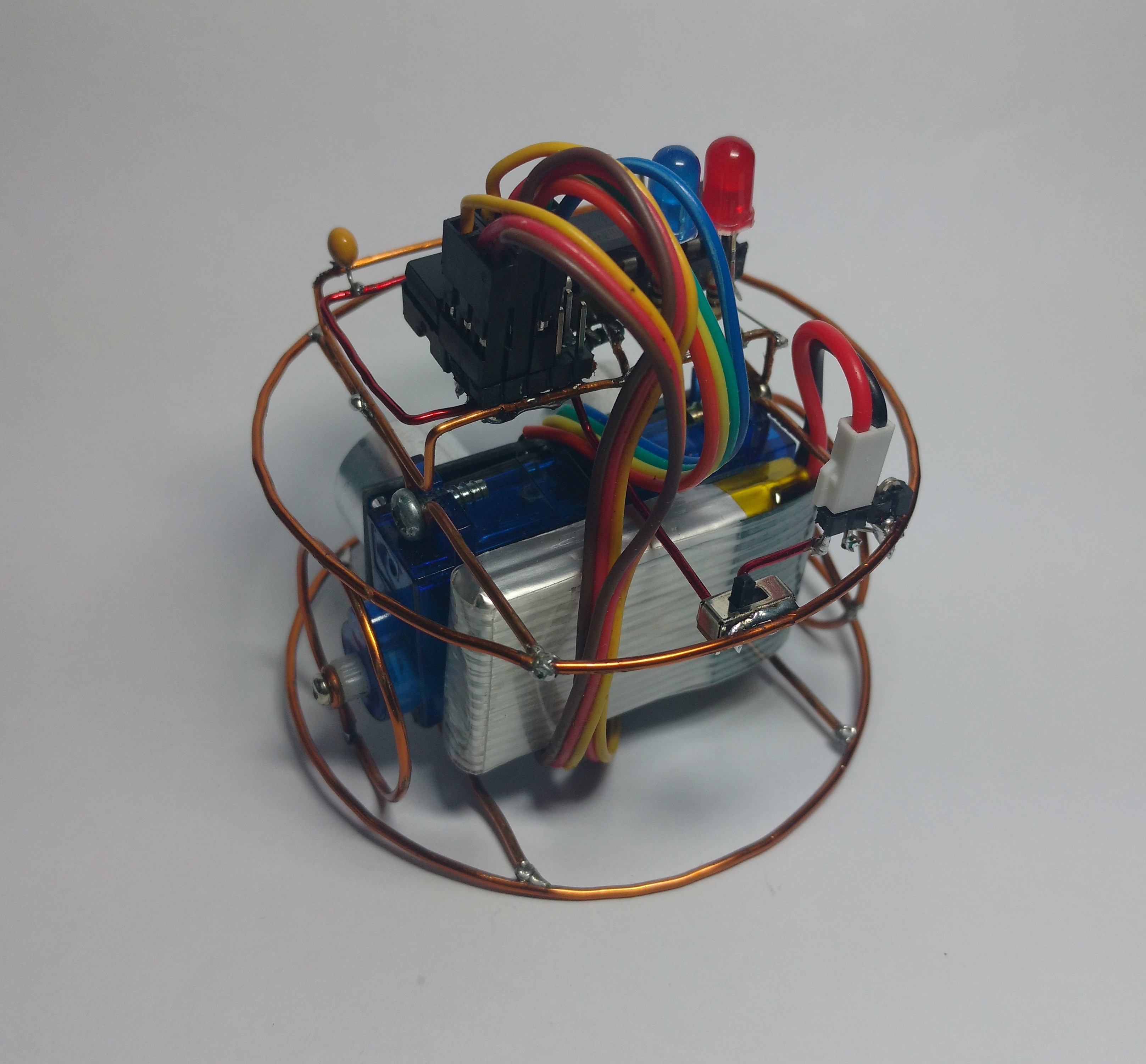
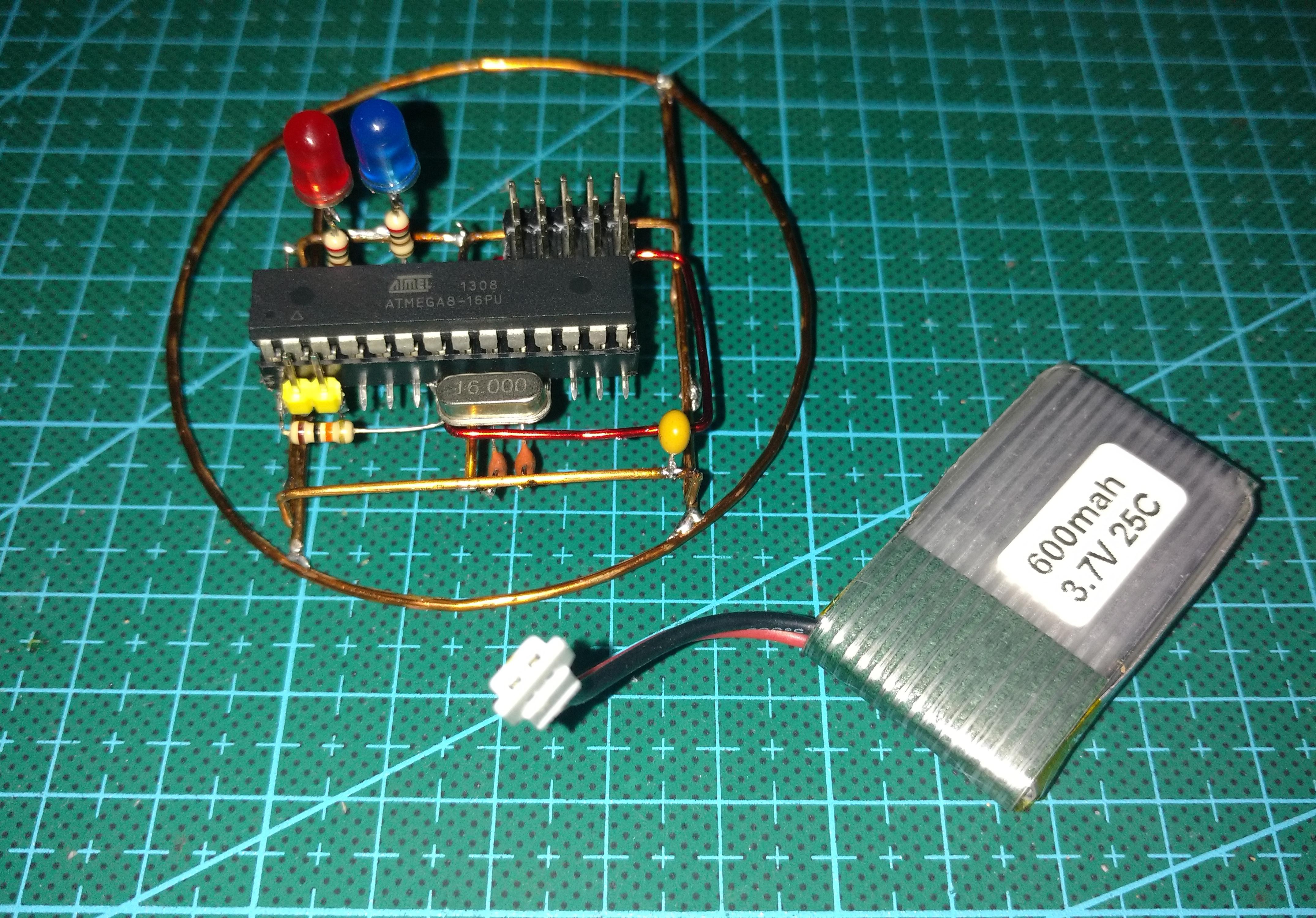
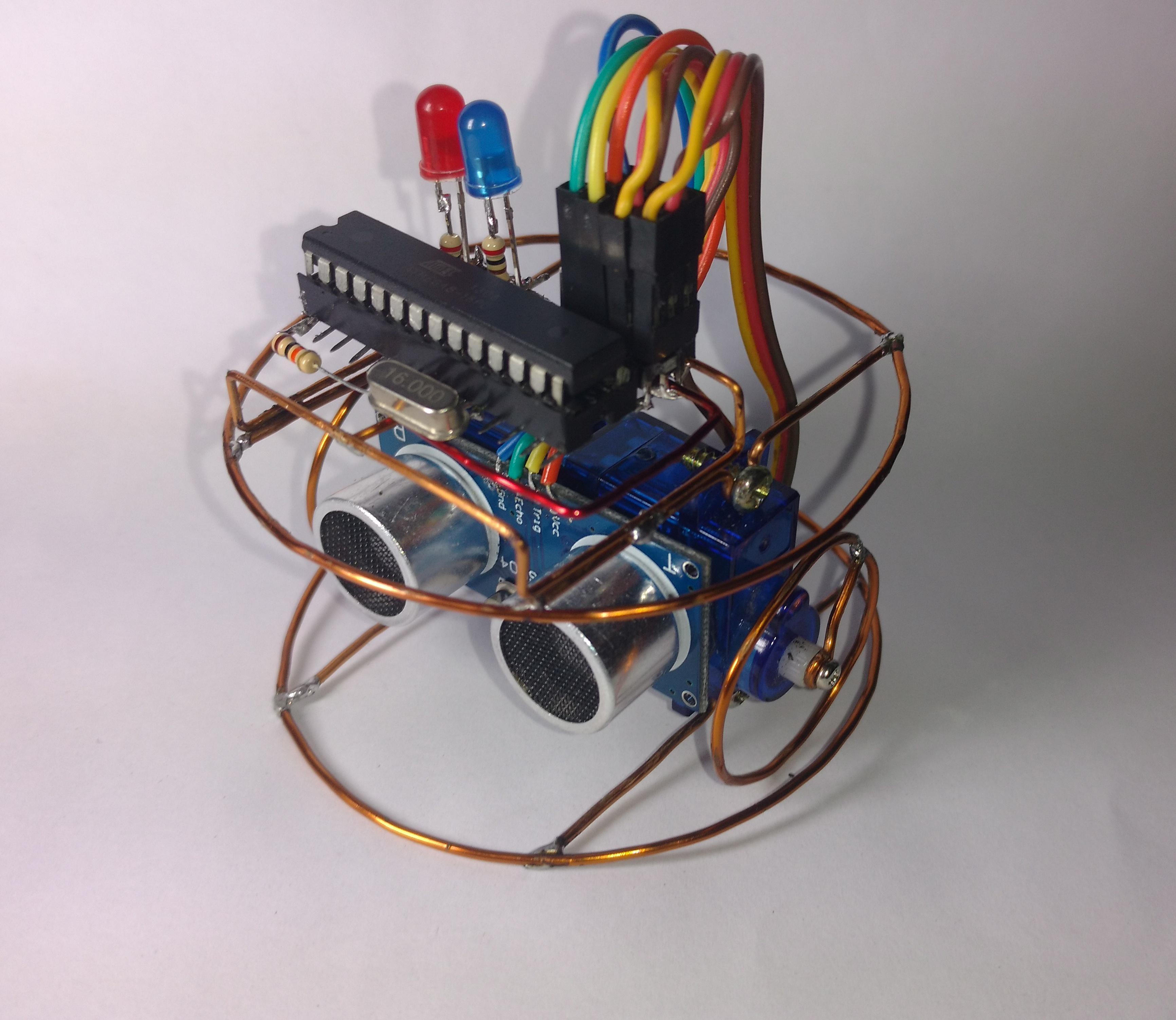
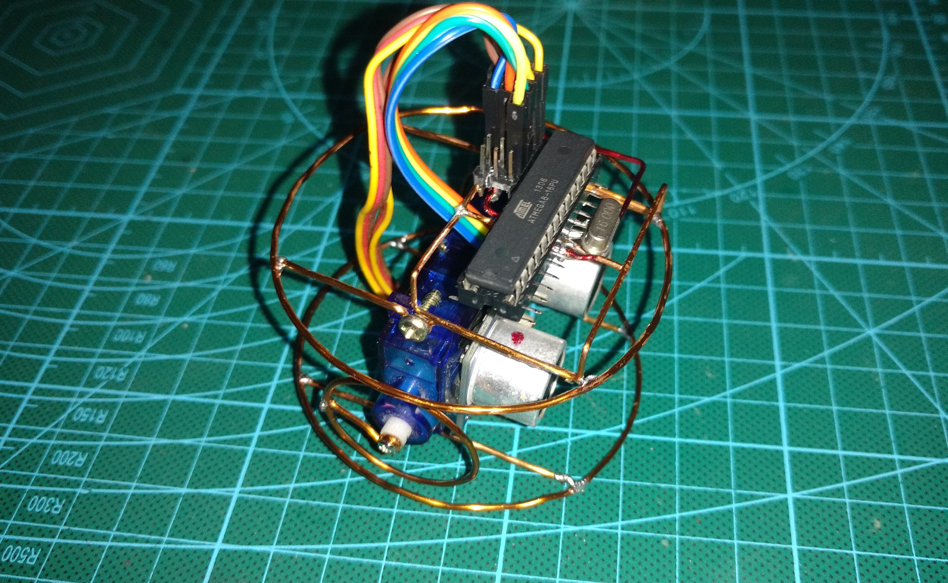
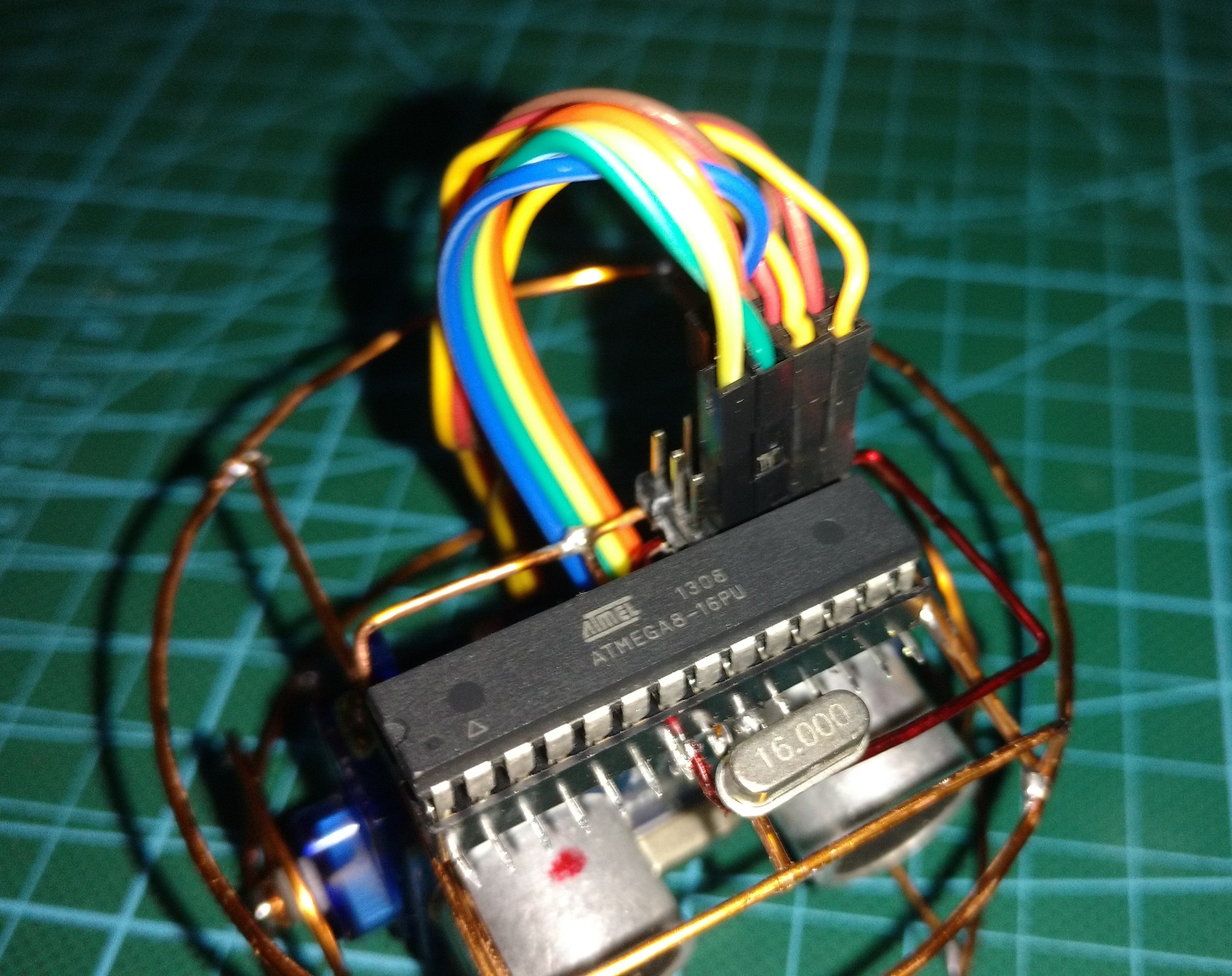
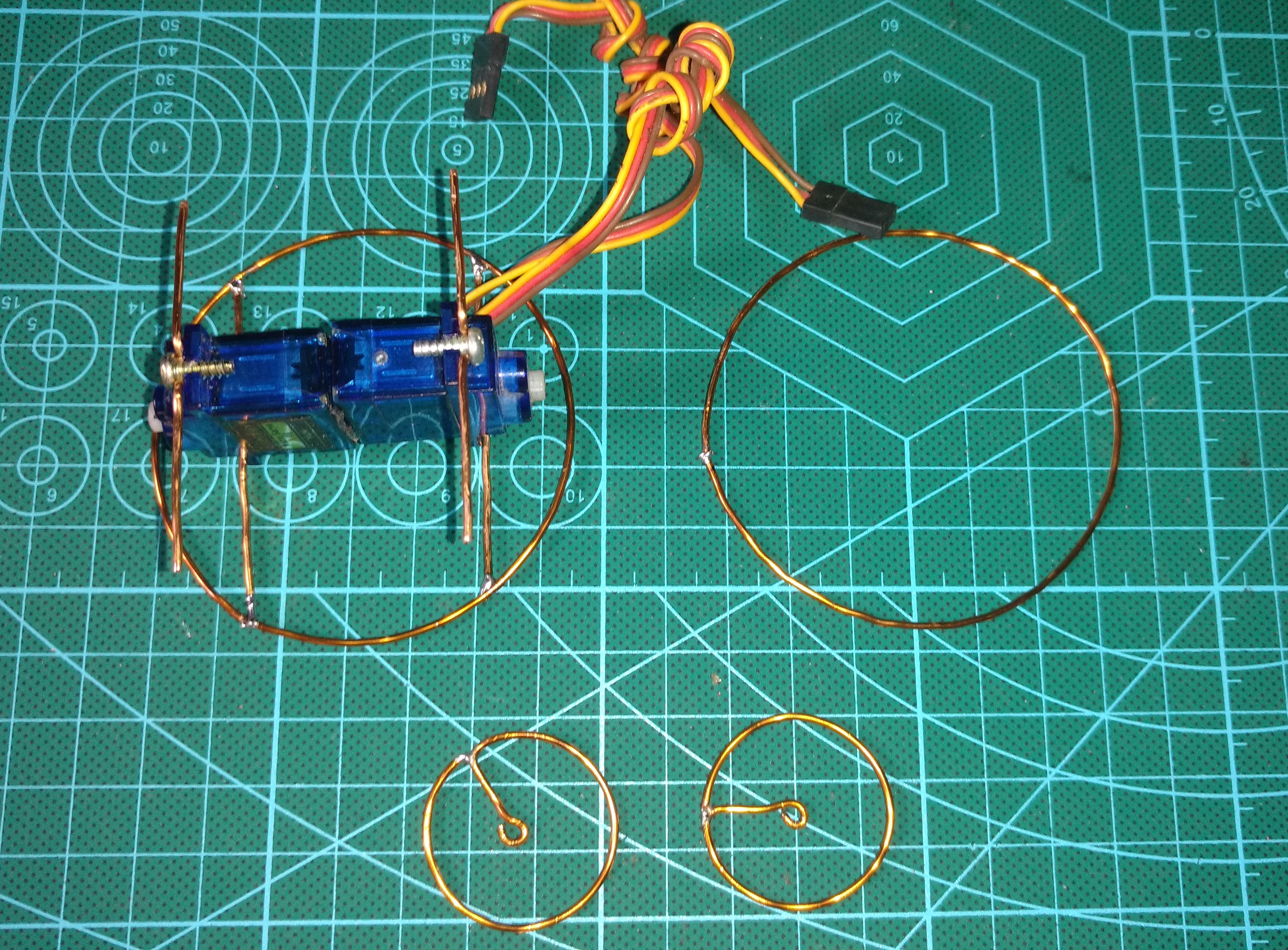
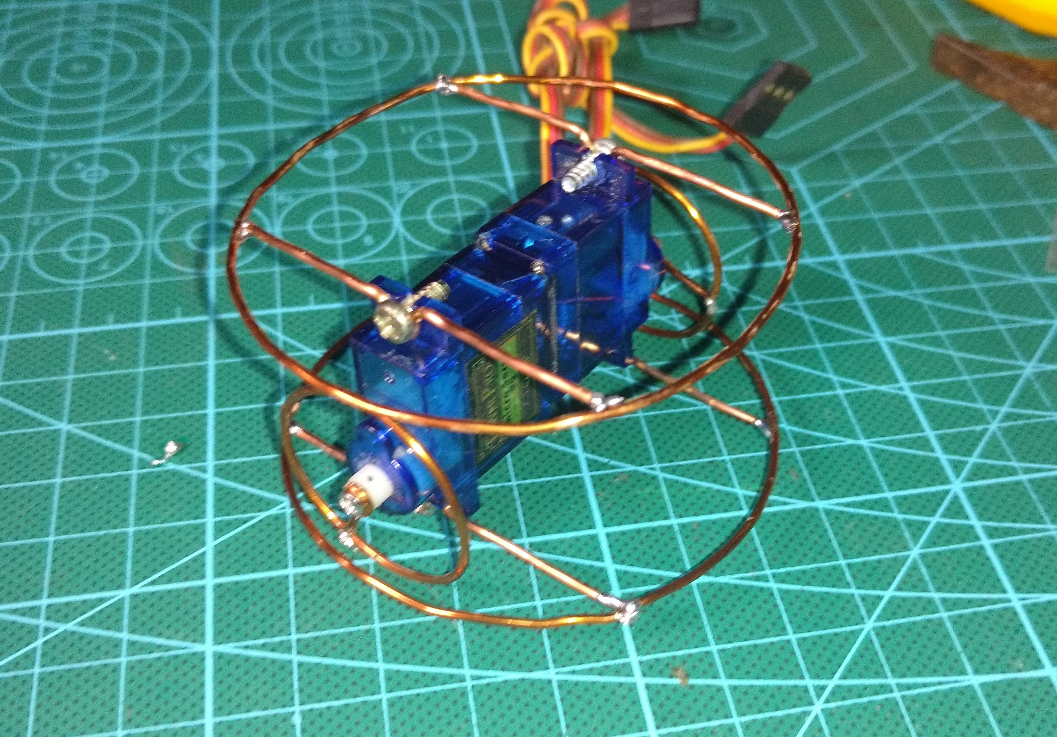
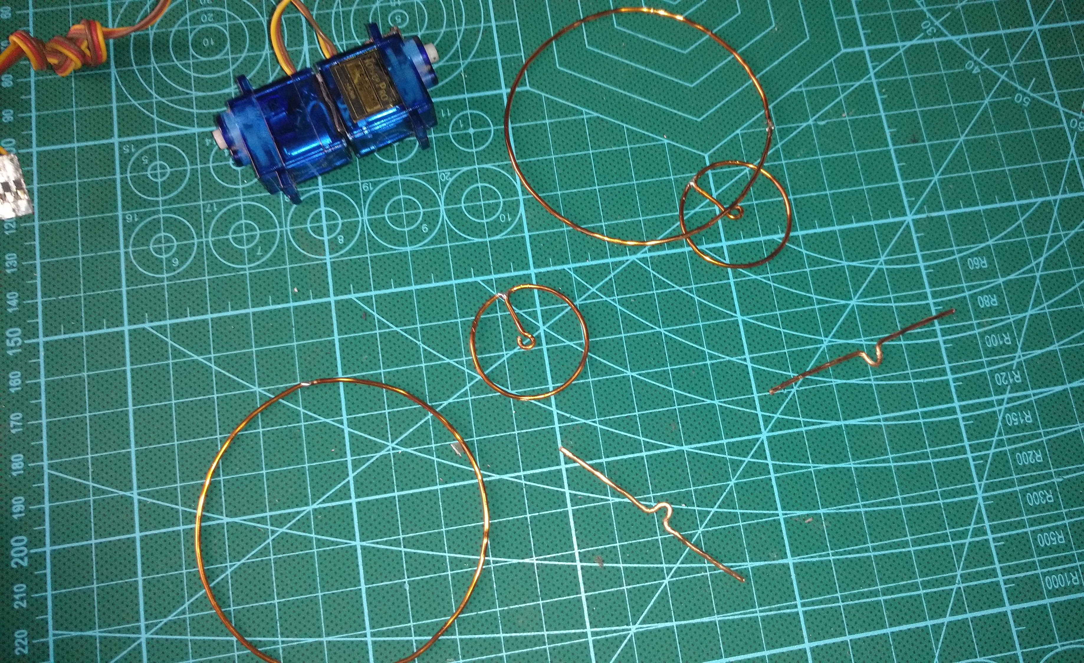
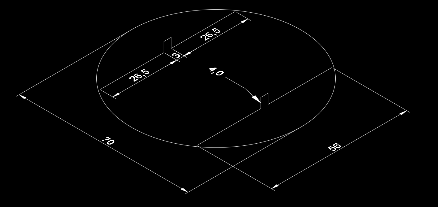
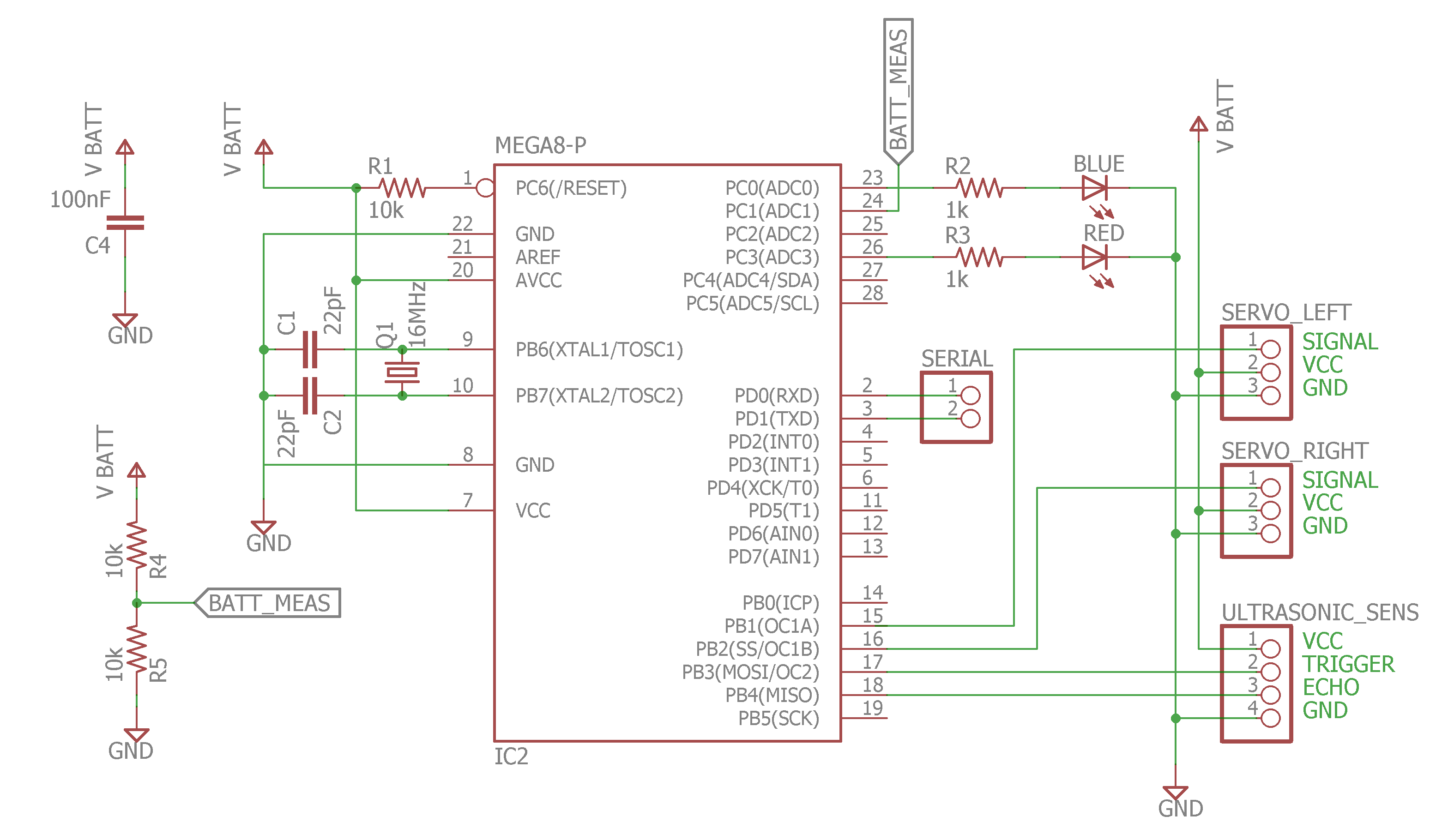
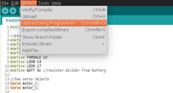
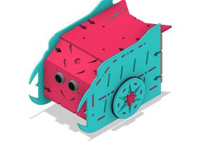
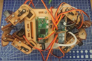
This is a tiny robot with chassis made from AWG 16 wire soldered together. The servos are micro servos hacked for continuous rotation, these also give the robot some support. The brains of the robot is an Atmega8 with code for avoiding objects with aid of an ultrasonic sensor.

When bulding this I had the wire "jump" at my face of throw solder at me, as it behaves as a spring. If you would make something like this, please use protection goggles . I know someone who lost an eye to a piece of wire when they were a child. Vision is too important to be careless.

freeformrobot.ino

The robot's Arduino code

x-arduino - 2.24 kB - 01/02/2019 at 23:34

Download

freeform robot schematics.sch

The robot's schematics in eagle format

x-kicad-schematic - 459.72 kB - 01/02/2019 at 20:18

Download

  • 1 × ATmega8 Microprocessors, Microcontrollers, DSPs / ARM, RISC-Based Microcontrollers
  • 1 × DIL28 Socket
  • 2 × 1K resistors
  • 3 × 10K resistors
  • 1 × 3.7 600mAh Lipo battery

View all 13 components

  • Finished the hardware

    RobsonCouto12/30/2018 at 22:28 0 comments

    Finally installed the battery and a power switch. I tried getting a reverse polarity protection feature to work, but none of the mosfets I had here seems to be able to saturate with the low voltage the battery provides.  I just have to be careful then :)

    Everything works as planned. Hope I can upload a video soon!

  • Battery and Voltage Monitoring

    RobsonCouto12/29/2018 at 01:20 0 comments

    Now that the microcontroller seems to be working fine with the other components, it is time to find a power source. I bought this 3.7 lipo battery for powering the robot, it is quite light and provides enough voltage and current to power the circuit.

    The circuit seems to work fine with just 3.7V, so I am glad I don't have to add in a step-up circuit, that would be a power waste and would not match the overall look of the project.

    Lipo batteries are know for causing trouble, so I have to take at least some care. These batteries cannot over discharge, so I use a free analog pin to monitor the voltage of the battery, which can somewhat represent the battery charge.

    I added a resistor divider (not seen in the picture, as it is under the microcontroller) connected to an analog pin. This resistor divider halves the battery voltage (4.2V max), which is then read by the microcontroller (2.1V max). As the battery voltage changes, the internal reference of the microcontroller is used instead of VCC. Thankfully, Arduino allows one to easily change the voltage reference of the microcontroller's ADC without direct register  manipulation. So I use:

    analogReference(INTERNAL); //sets the ADC reference to internal 2.56V reference

     Note: The ATmega8 has a internal reference of 2.56V, but most of the AVR Arduino boards actually have a 1.1V reference. 


    As the battery voltage (3.7 - 4.2V) is higher than the internal reference (2.56V), we need some trick in order to measure it. I have used a simple resistor divider. I used these blue resistors, which I despise because I cant read them without a meter, but have good precision (1%). Two 10K resistors split the battery voltage to a max of 2.1V. Sweet.

    To get the voltage measurement from the ADC, we multiply the value read by two(because of the divider), then by 2.56V divided by the resolution of the ADC (1024). This is done with the following line of code:

    battery_level = (analogRead(A1)*0.005);//0.005=2*2.56/1024;

    I plan not letting the battery voltage get any lower than 3.7V, so when that voltage is achieved, the robot will stop the motors and start to blink the LEDs, warning that the battery should be charged.

    I still have have to add a power switch to the circuit, and I am also at the moment looking for options for reverse polarity protection. I have had bad experiences with plugging batteries the wrong way in the past, and  would not like another one. My options are limited to the components I have at the moment though, as the deadline of the contest is approaching.

  • Programming the microcontroller

    RobsonCouto12/26/2018 at 23:52 0 comments

    To program the microcontroller I went on the simplest route, which is using Arduino. The ATmega8 can be programmed with the Arduino IDE very easily, without modifications to the IDE files (if you use a 16MHz crystal).  Simply choose "Arduino NG or older" on the boards list, then you can burn the chip directly with a supported programmer (I use the USBASP) or burn the bootloader if you are keen to program the chip with just a USB-serial bridge.

    I have implemented the following code, which allows simple obstacle avoiding. Pins 11 and 12 are used by the ultrasonic sensor (HC-SR04), while pins 9 and 10 are used by the servos.

    #include <Servo.h>
    
    // pin definitions
    #define TRIGGER 11
    #define ECHO 12
    #define MR 9
    #define ML 10
    #define LEDB 14
    #define LEDR 17
    
    #define THRSHLD 10 //cm
    
    Servo motor_r;
    Servo motor_l;
    
    int distance = 0;
    
    
    void setup() {
      pinMode(TRIGGER, OUTPUT);
      pinMode(ECHO, INPUT);
      pinMode(LEDB, OUTPUT);
      pinMode(LEDR, OUTPUT);
    
    
      motor_r.attach(MR);
      motor_l.attach(ML);
    }
    
    void loop() {
      distance = measure();
      if (distance > THRSHLD) {
        forward();
        blue();
        delay(200);
      } else {
        left();
        red();
        delay(50);
      }
    
    
    }
    
    int measure() {
      int duration, distance;
      digitalWrite(TRIGGER, LOW);
      delayMicroseconds(2);
      digitalWrite(TRIGGER, HIGH);
      delayMicroseconds(10);
      digitalWrite(TRIGGER, LOW);
      duration = pulseIn(ECHO, HIGH);
      distance = duration/58;
      return distance;
    }
    
    void blue() {
      digitalWrite(LEDR, LOW);
      digitalWrite(LEDB, HIGH);
    }
    void red() {
      digitalWrite(LEDR, HIGH);
      digitalWrite(LEDB, LOW);
    }
    
    void forward() {
      motor_r.write(180);
      motor_l.write(0);
    }
    
    void right() {
      motor_r.write(180);
      motor_l.write(180);
    }
    
    void left() {
      motor_r.write(0);
      motor_l.write(0);
    }
    

    The hacked servos are deprived of the closed loop positioning. The potentiometer used for knowing the position of the servo's shaft is replaced by two resistors of same value. This way, when telling the motor to go towards 180 or 0 degrees, the servo will try to reach this value, without success, rotating continuously in the process. The motor should stop at 90 degrees, but this depends on the motor and the precision of the resistors used. You have to find the value at which your motor stops, but it should be 90 degrees or very  close.

  • First tests

    RobsonCouto12/24/2018 at 00:57 0 comments

    I have tested the circuit components with the robot hooked to external 5V, the servos were working fine as intended.  As they are hacked for continuous rotation, setting them to 0 degrees makes them spin in one direction, while 180 degrees makes them spin on the opposite direction.

    The ultrasonic sensor I added on the last log was not working, but thankfully I had a spare one, which was new and still in the package, so no problem. I was afraid the chassis of the robot would get in the way of the sensor, spoiling the measurements, but thankfully the working angle of the sensor is sharp enough to avoid any changes on the structure.

    I also added two LEDs to report the readings of the ultrasonic sensor.  The red LED lights up when a obstacle is found, while the blue one is on when the path is free.

    Up next: Programming and then battery.

  • Started working on the electronics

    RobsonCouto12/19/2018 at 22:40 0 comments

    The ultrasonic sensor is held to the servos with double sided foam tape. I also had to shorten the servos' cables to achieve a cleaner look, otherwise they would be sticking out of the robot.


    Started to solder the basic microcontroller circuit, with the 16MHz crystal connected to the correspondent pins. I chose the ATmega8 simply because I have many of them laying around. It is Arduino compatible, although with only 3 PWM pins. For this task, however, it is more than sufficient.

  • Finished the chassis

    RobsonCouto12/19/2018 at 22:21 0 comments

    Finished soldering together the basic structure of the robot. I used magnet wire for the structure, which is coated with a thin layer of insulating material. I used a file or a razor knife to remove this material where the wires are soldered together.

  • Started Project

    RobsonCouto12/19/2018 at 22:11 0 comments

    I started by gathering some pieces of wire from the junk bin and figuring out the dimensions of the robot. I could not find the wire I wanted in the local stores, so I used 16 awg wire from old inductors.

    The servos were reused from another project and had already been hacked for continuous rotation long ago. I don't have pictures for that, unfortunately, but a tutorial can be found here. Heavy duty double sided tape was used to hold the servos secure back to back. 

View all 7 project logs

  • 1
    Chassis
    I did not plan the dimensions beforehand, just went cutting and soldering. However, I measured the parts of the chassis and sketched them so anyone interested can try. The dimensions are in mm and be aware that I measured with a simple ruler.  The structure below is used for the bottom and top parts of the chassis.

    You can visit the gallery for pictures of the building process of my robot.

  • 2
    Circuit

    I can't add step by step building of the freeform circuit, of course, but I can add the schematic of my circuit here as example. Then you can build it as you like, or just design your own with the microcontroller and sensors that suit you.

  • 3
    Programming

    This assumes you have basic knowledge of how to program a controller with a programmer. The code I use can be found in the Files section.

    The ATmega8 used can be programmed with the Arduino IDE. I used the mega8 because I have many of them, but an ATmega328p could have been used too.

    To program an ATmega8 with the Arduino IDE, just select Arduino NG or older  and ATmega8 from the Tools menu. Then select the programmer you have. If you don't have a standalone programmer, a Arduino can be used, just search online for "Arduino as ISP" 

    It is a good idea to use the "Burn Bootloader" option once, even if you don't plan to use it, as it also programs the correct fuse values into the chip. The microcontroller needs to be configured to use a external crystal, this is done separately from the code thru specif bits called fuse bits and they are not reset when you upload new code. The Burn Bootloader option does that automatically, then you can overwrite the bootloader with the "Upload Using Programmer" tool, which keeps the fuse bits programmed.

    Then you can program the chip using the Upload Using Programmer option. Just select under the Sketch Menu. Skipping the bootloader gives you extra flash, but I use it simply because the bootloader for the ATmega8 takes forever to startup the main code.

View all 3 instructions

Enjoy this project?

Share

Discussions

Doug wrote 12/31/2018 at 21:05 point

I can have a friend at last!!! ;)

  Are you sure? yes | no

RobsonCouto wrote 01/01/2019 at 22:16 point

Thanks for the interest in the project! xD

  Are you sure? yes | no

rad wrote 12/28/2018 at 21:25 point

Very innovative using minimal parts to build a robot and for hacking the servos and putting them in that configuration to power the wheels.  Really great.  Thanks for sharing.

  Are you sure? yes | no

RobsonCouto wrote 12/29/2018 at 00:22 point

Thanks for the comment! I am glad you like it :)

  Are you sure? yes | no

Elliot Williams wrote 12/20/2018 at 19:36 point

Love the wheels!

  Are you sure? yes | no

RobsonCouto wrote 12/21/2018 at 16:04 point

I'm glad. Thanks for the comment!

  Are you sure? yes | no

deʃhipu wrote 12/20/2018 at 16:04 point

I experimented with paperclips soldered to the PCB for chassis before, and it worked good, but I never thought about using only wire. Looks like a very good idea, and it's accessible and easy to get.

  Are you sure? yes | no

RobsonCouto wrote 12/21/2018 at 16:03 point

Thanks! I only had this idea because of the contest though. It seems sturdy enough for regular use, but I guess it would not stand very well if falling of a desk or bench for example.

  Are you sure? yes | no

deʃhipu wrote 12/21/2018 at 16:14 point

A regular 3D-printed or laser-cut robot would probably break as well. Here you can at least bend it back into shape.

  Are you sure? yes | no

RobsonCouto wrote 12/21/2018 at 16:27 point

So true. Had not thought of it this way.

  Are you sure? yes | no

davedarko wrote 12/20/2018 at 08:49 point

wow, this is awesome! Good luck with the contest!

  Are you sure? yes | no

RobsonCouto wrote 12/20/2018 at 14:36 point

Thanks!! You too!

  Are you sure? yes | no

Similar Projects

Does this project spark your interest?

Become a member to follow this project and never miss any updates