 Dan Popescu
Background:
In a hybrid / off grid system, when the sun power is higher than sum of loads (AC &DC), the power is wasted. Diversion of the excess power is one of the alternative to use "every single electron".
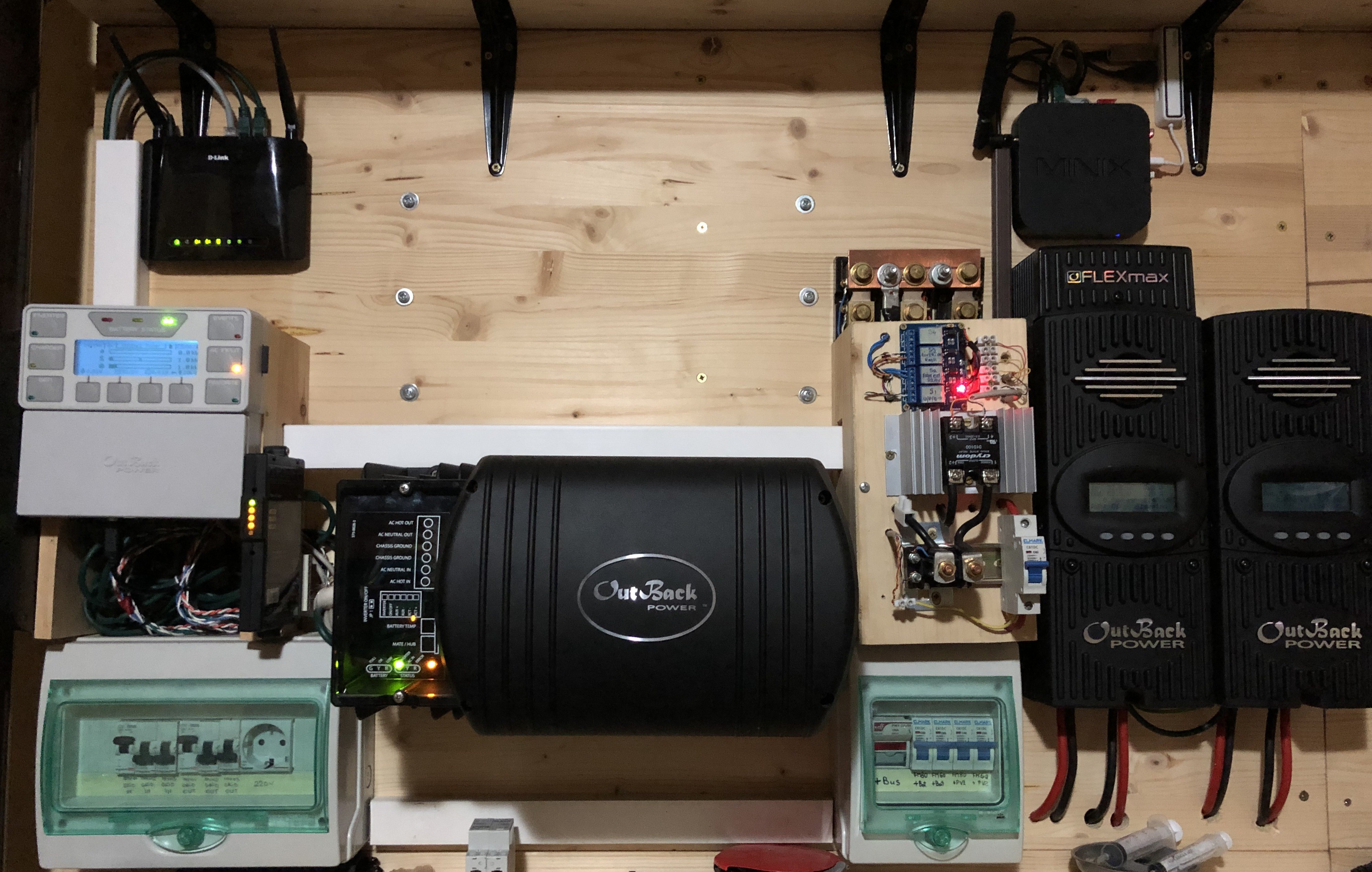
My solar system configuration:
- PV arrays: 4000W (2 strings X 2000w)
- Battery bank: Lead Acid flooded - 48v, 400A
- Inverter: VFXR3048E Outback power - 3000w
- Charge controllers: FlexMax60 + FlexMax80 (one per PV string)
- System controller: Mate 3
- Battery controller: FlexNet (Shunt A, B, C)
****************** PART 1 *****************
Diverter module:
- SSR: Crydom D1D100 (100A) connected with a 48v/1500W resistive DC load, immersed in a hot water boiler
- 60A DC breaker
- 48V / 200A DC High Current Relay Contractor (optional)
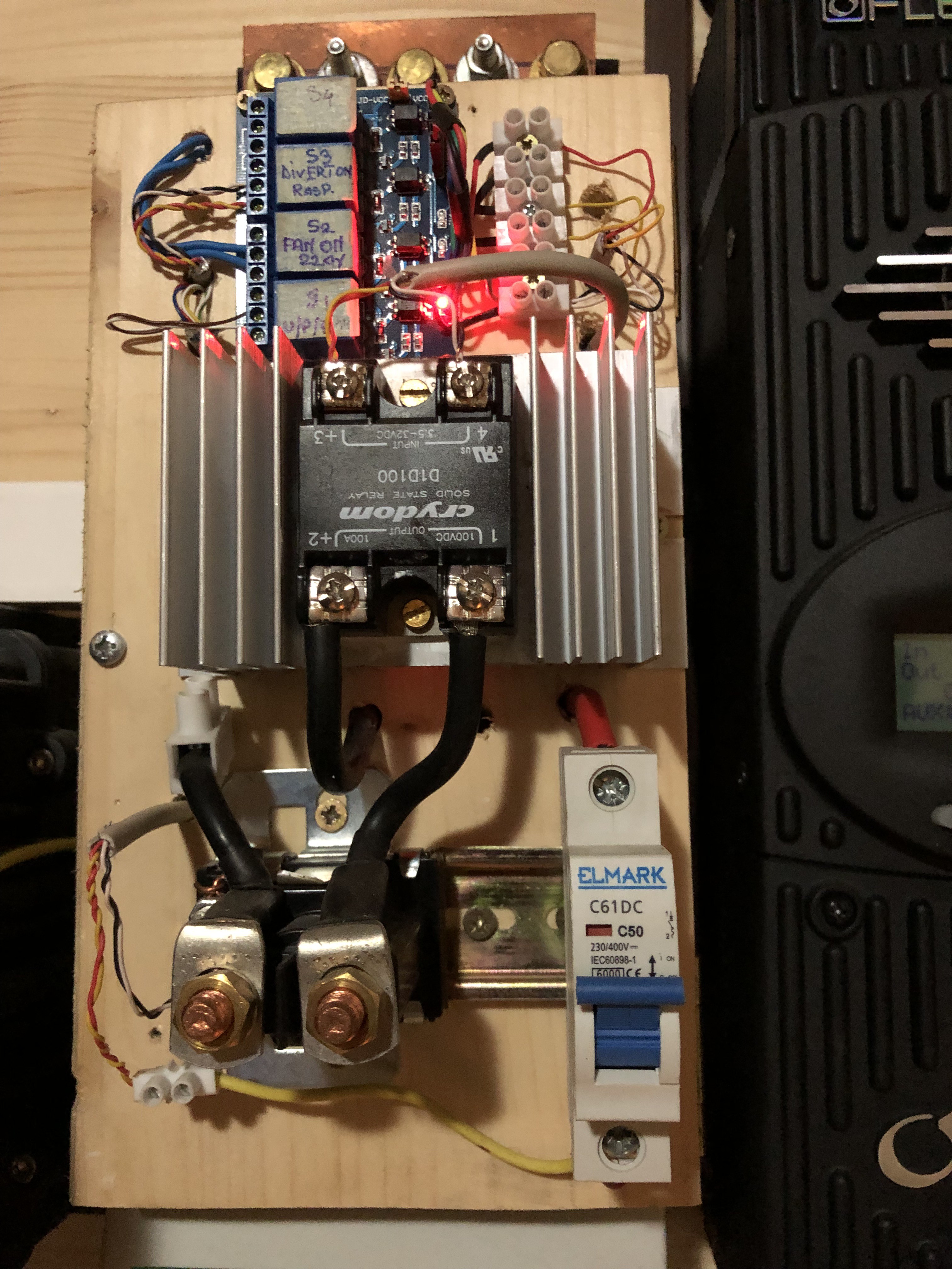
Hardware connection:
FM60: AUX output - not used
FM80: AUX output - connected with SSR pin 3 and 4
SSR: pin 1 connected to battery negative trough Relay Contactor (if it is used*)
SSR: pin 2 connected to resistive load 1st pole
Resistive load (1500w) - 1st pole connected to SSR pin 2 , 2nd pole to battery positive trough DC breaker
Relay Contactor: 48v coil - command is coming from inverter AUX, via additional 12v relay.
*This is just for additional protection to prevent SSR to remain active (for any reason) when the battery fall below 52v. Never happens until now after 1yr of usage.
Final system settings:
FM60: AUX not used, absorption and float with 0.1V above set point
FM80: AUX connected with SSR, absorption and float on the set point
FM80 settings:
AUX MODE: Diversion Solid State
• Relative Volts: 0 V
• Hysteresis: 0 V
• Hold: 8 seconds
• Delay: 5 seconds
SSR: Crydom D1D100 (100A) connected to a 1500W resistive DC load, immersed in boiler
Inverter: VFXR3048E - grid available, Grid Zero mode selected
Mate3: HBX mode activated
FlexNet:
Shunt A: DC to battery bank
Shunt B: DC to inverter
Shunt C: DC to divert load (1500W resistor)
Results:
Diverter is working, using total available solar power while keeping the battery in float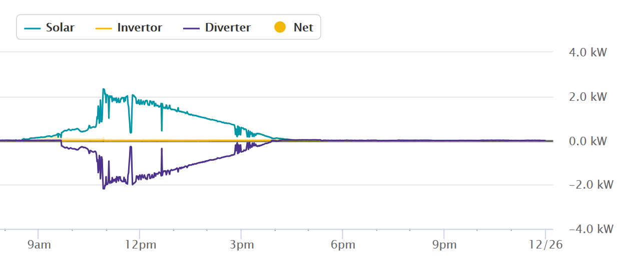
 ****************** PART 2 *****************
Prerequisites:
- DC diverter (part 1) up and running
- MonitorMate installed and running (Web Server on Synology/Raspberry PI/MiniPC)
- Raspberry PI board
- 5v Relay board
- WiFi Power Socket
- WiFi Transmiter
- USB temperature probe (enhancement feature)
Working principle:
Diverted DC Power is constant monitored trough shunt C using Monitor Mate. Monitoring data are exported in a JSON file every minute and saved on the Web server location.
Raspberry PI board is connected to the network. SolarPowerDiversion software (Python based) is installed and running. The script read and analyze the JSON file and when various conditions are met, decisions are made.
When the power diverted reach a stable level (i.e >1000 W) , enough to power an AC load (i.e Air conditioner), 5v relays are activated via Raspberry PI GPIO.
5 v relays are hardwired with the WIFI transmitter which ON/OFF WiFi power sockets. In the WiFi sockets you can plug whatever you need.
There are two levels of AC loads.
Load 1 (socket 1) - active when DC diverted power is >1000w
Load 2 (socket 2) - active when Load 1 is active and again DC diverted power is >1000W
When Raspberry PI was up and running additional enhancement for part 1 - diverter was made in order to prevent over heating of the boiler. For this, an USB sensor with a temp probe was attached to the mini PC. Dedicated software was configured to save in the common Web Server location the output file with the actual temperature. The script running on the Raspberry is reading the file and OFF the Relay Contactor of diverter if the boiler temperature is above 85 degree. To implement this, initial diverter module hardware configuration was changed: Relay Contactor command was changed from Inverter AUX (previous set in part 1) to one of Raspberry PI attached relay.
This is not a mandatory feature, but is needed based on my experience....
Read more »
 Paul Crouch
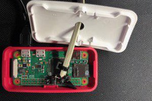
 rifowler
 Xiaoj329
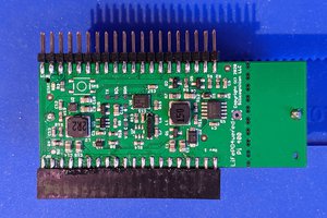
 Patrick Van Oosterwijck