 Ted Yapo
So, I'd like to find a CMOS logic gate with complementary outputs - you know, like ECL, CML, LVDS, or any of those differential signaling families. It's not for a logic application; it's for driving a diode sampling gate with a truly differential pulse - transformers just aren't cutting it (story for another log!). I don't think such things exist, so I came up with this. Can I do better? What do you think?
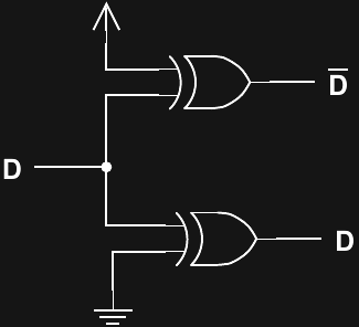
I'm hopeful that if I use two devices from the same gate package, I can get a small timing difference (skew) between the two outputs. I'm looking at the 74LVC2G86 right now, because I need the large voltage swings afforded by a 5V supply and the 32 mA drive.
I had considered somehow using the Q/Qbar outputs of a d-flip-flop, but I think there are a few problems with that.
Discussions
Become a Hackaday.io Member
Create an account to leave a comment. Already have an account? Log In.
So what you want is a converter for a single-ended signal into a differential signal.
https://en.wikipedia.org/wiki/File:ECL.svg shows a basic ECL gate. You could implement one with discrete logic and wider swing, or even : buffer a classic ECL gate with external FAST transistors ?
Are you sure? yes | no
Ted, can you tell us more about the diode sampling gate? Would a LVDS transmitter fit the spec for driving it, or are they too expensive, or too slow, or too slow when not too expensive?
Are you sure? yes | no
yeah, sorry for the teaser. I'll find some time to post a detailed log about the thing soon. I have a first failure to report :-)
Any of the real differential logic devices have too small an output swing (I think) to be useful for driving a sampling gate. I've looked at PECL, CML, RSPECL, LVDS, etc. They all keep swings low to reduce EMI. You need a large voltage swing combined with a decent-sized resistor to emulate a current source driving the diode bridge. I've even looked into laser diode drivers, which are plenty fast and work in current mode, but I think they may lack the compliance required (LD's get driven in a relatively small voltage range around the bias point).
I'm still holding out hope that I might get a PECL device to work. I found the MC10EP89, an ECL driver with 2x the output swing designed for double-terminated cables. This might work, but haven't had a chance to test it yet:
https://www.onsemi.com/pub/Collateral/MC10EP89-D.PDF
In traditional samplers, the pulse typically comes from a step-recovery diode. Mouser stocks a medium-speed one that might work for a lower-bandwidth sampler, but I really would like to find a way to use some of the modern fast commodity parts.
The CMOS thing is just for a first test - the edges are way too slow for what I'd really like, but I'm learning to crawl before I try to walk.
Are you sure? yes | no
Oh, then I have a good news for you: LVDS transmitter outputs are actually current sources.
I was intrigued so I looked it up today before I asked you that.
I actually looked it up on wikipedia, then data sheets of chips available at Digi-Key ... it is just that they seem a little too slow at first glance, maxing at something above 80MHz.
Some faster generations of LVDS, such as CML, have output stages consisting of current sinks and 50 ohm pull-ups, therefore they are too able to swing widely, provided they are not terminated "properly", i.e. not connected to proper CML receivers at distant end of line.
Are you sure? yes | no
@salec Unterminated outputs have 2x the swing, but it's still too small. I have some CML-output comparators here (as used in the fist log on this project). They have internal 50-ohm source terminators and 16 mA drive, which sets the maximum swing (no external term) at 800 mV (1.6 V differential). This is better than the 400/800 mV you get with external termination, but still not nearly enough. I haven't seen any CML outputs without the internal 50-ohm terminators.
But, even if you found them without the terminators, I doubt the output current drivers have enough compliance range to generate a large swing.
Are you sure? yes | no
Oh, yes you are right! I didn't thought it through ... the 50 Ohm pull up can't be overwhelmed enough by a meager 16 mA sink, it's Ohm's law (facepalm).
Oh, well ... perhaps something with fast discrete transistors?
Are you sure? yes | no
There is some badassery going on here :-P
You could tune the propagation time with one small potentiometer at one input, right ?
Are you sure? yes | no
Yeah, I guess I could :-)
I wonder how stable it would be? At least if I just use two gates, I can hope that differences between them track with temperature.
More research required. And more funding.
Are you sure? yes | no
more fun and more ding !
Are you sure? yes | no
Hi Ted.
I believe there is one thing you are missing: XOR gate is just a rug, under which an extra inverter in one of the signal paths is swept.
When one of the inputs is held on an logic level, the propagation delay time from another gate input to the gate output will be different depending on the level present on first input.
XOR is identical to a multiplexer selecting weather the signal goes over an inverter or directly.
Coincidentally, it creates an symmetric circuit and a commutative logic function which we conveniently call eXclusive OR.
Are you sure? yes | no
Yeah, I agree that the usual implementations you see for XOR would result in unequal delays. But, I occasionally see things like this from @Yann Guidon / YGDES
https://hackaday.io/project/8449-hackaday-ttlers/log/150147-bipolar-xor-gate-with-only-2-transistors
that make me wonder if at least one of those topologies would make it work. I could go through them all and check, but it's a moot point if they're not being used inside available parts. Next time I'm in the lab, I'll find a 74AC86 and test it out.
Are you sure? yes | no