 Ted Yapo
Until now, I believed that such a gate was the stuff of myth, like rainbow-farting unicorns. Now that I've finally found the 74LVC2G157, I'm going to take a little closer look at every horse I see, just in case.
So, here's the deal: the Y and Ybar outputs of the 74LVC2G157 2:1 multiplexer are as close to a differential output as you can find. I had previously measured the Q and Qbar outputs of a 74AC74 flip-flop and found them to have pretty low skew, but the fact that it's a flip-flop makes it a little difficult to use as an output buffer. The 74LVC2G157 seems even better, plus being 74LVC logic, has rise and fall times around 500 ps or so.
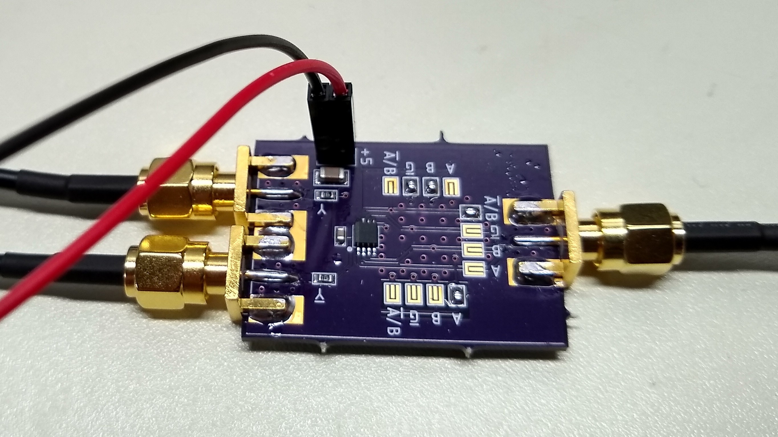
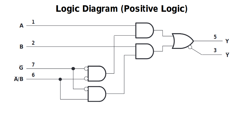
I designed a lavish breakout PCB to test this part mostly because I didn't feel like soldering the tiny SSOP pins by hand. The board has solder bridge footprints to allow any of the inputs to be connect to ground, +V, or the input signal. It turns out I only needed to test one combination. The logic of the mux is straightforward: Abar/B selects one or the other input to be routed to the output, when the Gbar input is low. The output is provided as Y and Ybar, which can be abused as a differential pair for all sorts of nefarious purposes. This is my kind of part!
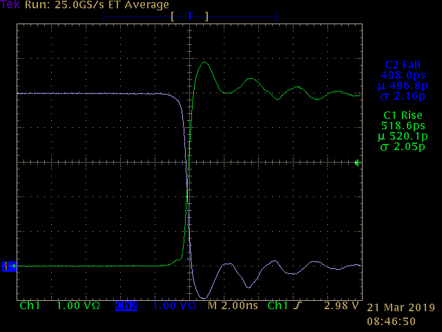
By tying the A input low and B input high, the output follows the Abar/B input, producing a differential-output buffer. The output looks really good on the scope: the outputs transition in around 500 ps, and cross at about 1/2 the supply voltage, indicating a relatively low skew. I didn't measure the skew between the outputs directly, but it looks small enough to be useful. I'm not sure where the ringing is coming from; the outputs are probed with 10:1 resistive Z0 probes which should be fine at these speeds. It may be cheap RG174 cables from ebay - I'll have to re-test with some decent RG316 ones I have around somewhere. At least the ringing is relatively symmetrical and balanced.
Zooming in a bit, we get a better look at the transitions:
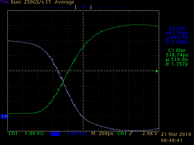
The traces don't cross exactly at 1/2 the supply voltage, indicating some possible skew, but it's relatively small. This could also be due to some other factors: I didn't check the two oscilloscope channels for perfect alignment, for instance. In any case, this is good enough to do some further work with. It's certainly better than tuning a couple of XOR gates.
Just to put this into perspective, this part is generating a 10 V differential step in half a nanosecond (it could be pushed to 11 V and still be within the recommended range according to the datasheet). This is plenty good enough to create a sampling pulse for an sampling oscilloscope of several GHz, since the diodes will switch on a much shorter segment of the transition. There was an old design for a sampling scope in Electronic Design (nearly 20 years ago now!) that achieved 1 GHz bandwidth with 2.2 ns transitions from the output of a comparator. This transition is nearly 5x faster. That's pretty exciting.
I also have some breakout PCBs for laser diode drivers with 25 ps transitions being fabbed at the moment, but this CMOS multiplexer might enable some incredibly-dirt cheap applications, like maybe a standalone (no oscilloscope required) TDR with spatial resolution in the cm range.
EDIT:
You know, in the rush I designed this PCB, I didn't check that the traces on the PCB are exactly the same length. There probably isn't much difference, but it could be a contributing factor.
Discussions
Become a Hackaday.io Member
Create an account to leave a comment. Already have an account? Log In.
Have you considered trying to replicate the Tek S-4 traveling wave sample gate? The SD-24 I believe uses something similar. It has the big plus that it only needs one sharp edge in the sample pulse, not a short duration pulse. The sample duration is determined by the propagation time (physical length on one trace section) of the differential sample edges switching the diodes. The trace section voltage between two non-conducting diodes is then measured. The Tek original was built on an exotic ceramic substrate, but don't offhand see why at lower performance it could not be built on a low-cost 4 layer PCB. It took a lot of looking at the article to understand how on earth a S-4 sampled, but the paradigm shift moment when I realized the trace was the capacitor. I
Have you also pondered on the trigger problem? I see you now have a 11801, which was the model without the delay line. The 11802 came with delay lines with integrated trigger pickoff. You could then see the trigger point and before. The downside the delay line only has a few Ghz bandwidth.
Another strategy on the trigger delay is random sampling, so samples just fires randomly, some before the trigger event some after. A time ramp can be sampled in addition to the signal to place the sample on the timeline.
Another cheap trigger strategy seem like it might be a prescaler chip, so you split the signal to sample and prescale into some stable lower frequency to run all the trigger timing.
One other trigger strategy was used on the HP Vector Voltmeter. It uses a low frequency PLL on the reconstructed sample output (20 khz I believe). This process is all documented in old HP bulletins. You had to tell it the correct band of the fundamental frequency, but then it could adjust the PLL VCO based on looking at the much lower frequency samples, until they were a perfect subharmonic. With the PLL just a tiny bit from locked, it generates sequential pulses to sweep. The samplng bridges were in the probes too. I've played with microcontrollers adjusting a OCXO to make a GPSDO, and it's not so hard to get the frequency locked with amazing precision.
Some PIC microcontrollers (24F and MX32) have a thing called a CTMU, which among other things can generate precise short delays or measure short times. It was suggested in one discussion I saw a few yaars ago, you might with careful design get the CMTU into the few hunded ps range. Not a 11802 witth a SD-24, but for a $4 microcontroller, curious.
if you apply serious software, there are a variety of strategies to generate samples without the trigger. Google "compressed sensing". I believe one strategy was based on carefully random samples and mathematically extracting the signal which will not be random but is repeating so will cause statistically detectable variations. I believe another strategy used mutliple sampling frequencies, at like prime frequencies and the resulting virtual sampling frequency was the primes multipled. Values like primes around 99K and 101K, gives a sparse virtual sample rate of near 10 Ghz. Replacing trigger hardware with math sounds like an attractive way to get the cost low, especially if you do something like connect the device to a PC with USB. The PC can for example run serious math on a GPU.
Keep up the excellent exploration! A lot of modern electronic design needs test equipment way beyond DIY budgets, but perhaps there is a way to make "good enough" test equipment with modern parts at low cost and easily avaialble. I'm convinced aliens worked at Tek in 1990. Things like the Tek 118xx are still pretty impressive, and really useful, and not outrageously priced in ebay. Unfortunatly the supply is very limited, and they are finicky and easily damged. I ended up getting 4 old Tek scopes to make 2 that worked correctly. And some ebay finds were just dumb luck, like the really grungy box of Tek stuff, which when I looked really close included a SD-24. I won the box of junk for $100, and the SD-24 works perfectly.
Are you sure? yes | no
great find!
Are you sure? yes | no