General Features
- Closed loop system with gyroscopes.
- Complete system simulation in MATLAB for PID tunning.
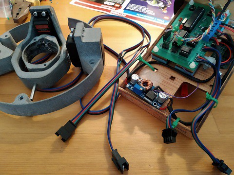
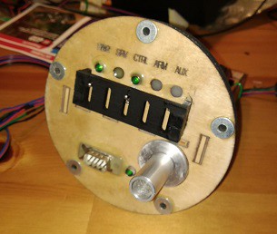
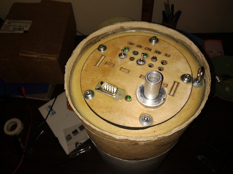
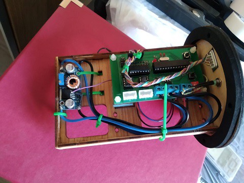
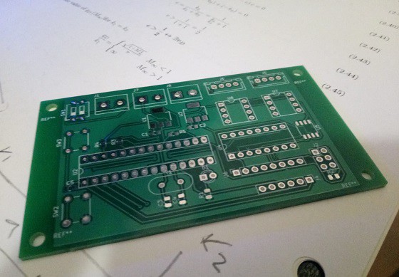
- Custom made PCB for control.
- Remote emergency deployment of parachute.
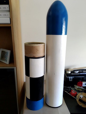
- Without fins.
- Simple parachute deployment with commercial electronics.
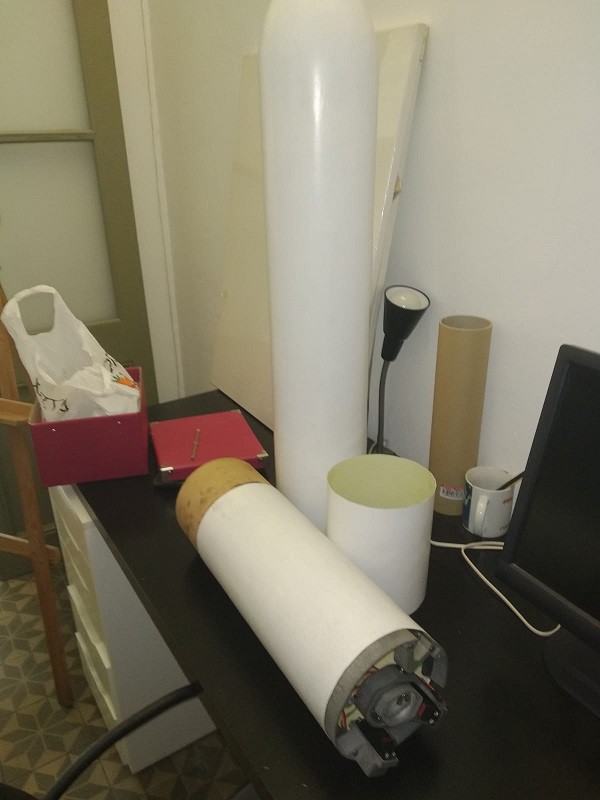
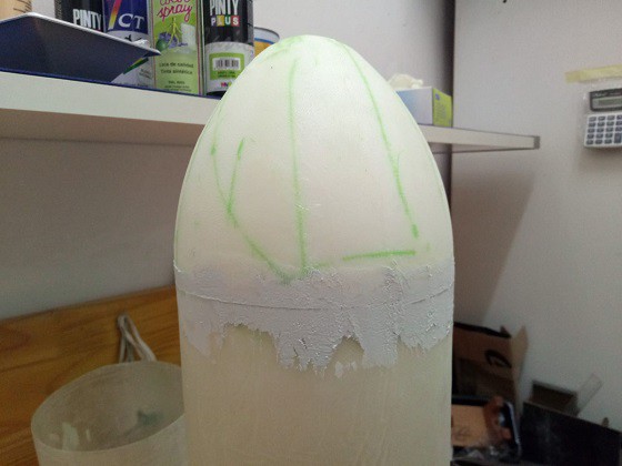
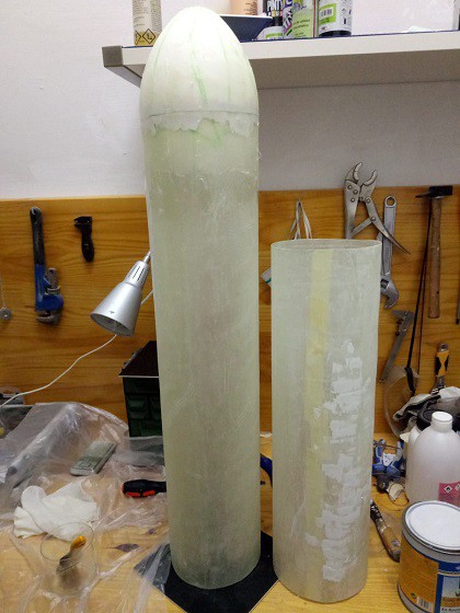
- Fiberglass body tube with wood reinforcements.
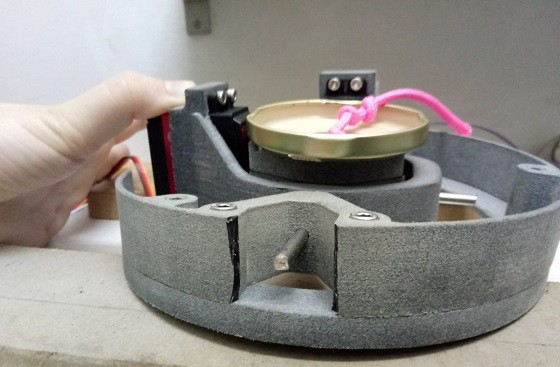
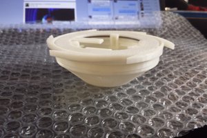
- Two DOF motor vector system.
- 3D printed gimbal with hobby servos.
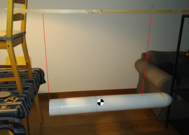
- Finite Element validated gimbal structure design
Active Stabilization
- Closed loop control system.
- Set point, zero angular velocity in rocket transverse axes (behaviour equivalent to fins).
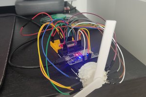
Control PCB Features
- Based on ATMEGA328P
- uC running an 5V and 16 MHz
- 3.3V for some components
- 6.5V for servos by means of an external DC-DC buck
- Reading servos actual position by means of two external MCP3201 12bit ADC's via SPI
- Flight data storage in flash memory Winbond W25Q64
- Inertial mesurement unit GY-91 with BMP280 and MU9050
- PWM control of two servos.
Status
- Feasibility study by means of simulation (COMPLETED)
- Design of the gimbal (COMPLETED)
- CAD (COMPLETED)
- Finite Element Analysis (COMPLETED)
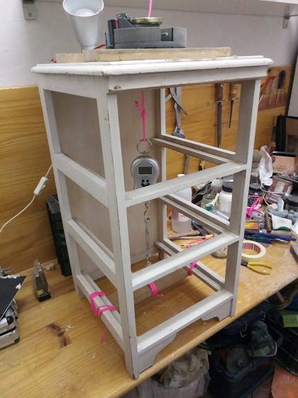
- Static testing (COMPLETED)
- Control PCB (IN PROGRESS)
- Schematic (COMPLETED)
- PCB design (COMPLETED)
- Manufacturing (COMPLETED)
- Programming the control PCB (ALMOST COMPLETED)
- Design of the rocket (COMPLETED)
- Fabrication (ALMOST COMPLETED)
- Gimbal (COMPLETED)
- Fiberglass body tubes and ogive (COMPLETED)
- Assembly (ALMOST COMPLETED)


 flamefire
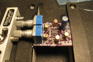
 AVR
AVR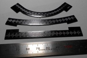
 Roman V
This is super awesome! I am curious how you got the Mass Moment of Inertia to PID value relation which is what I am struggling with due to my lack of knowledge