 Darren V Levine
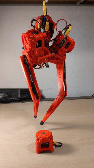
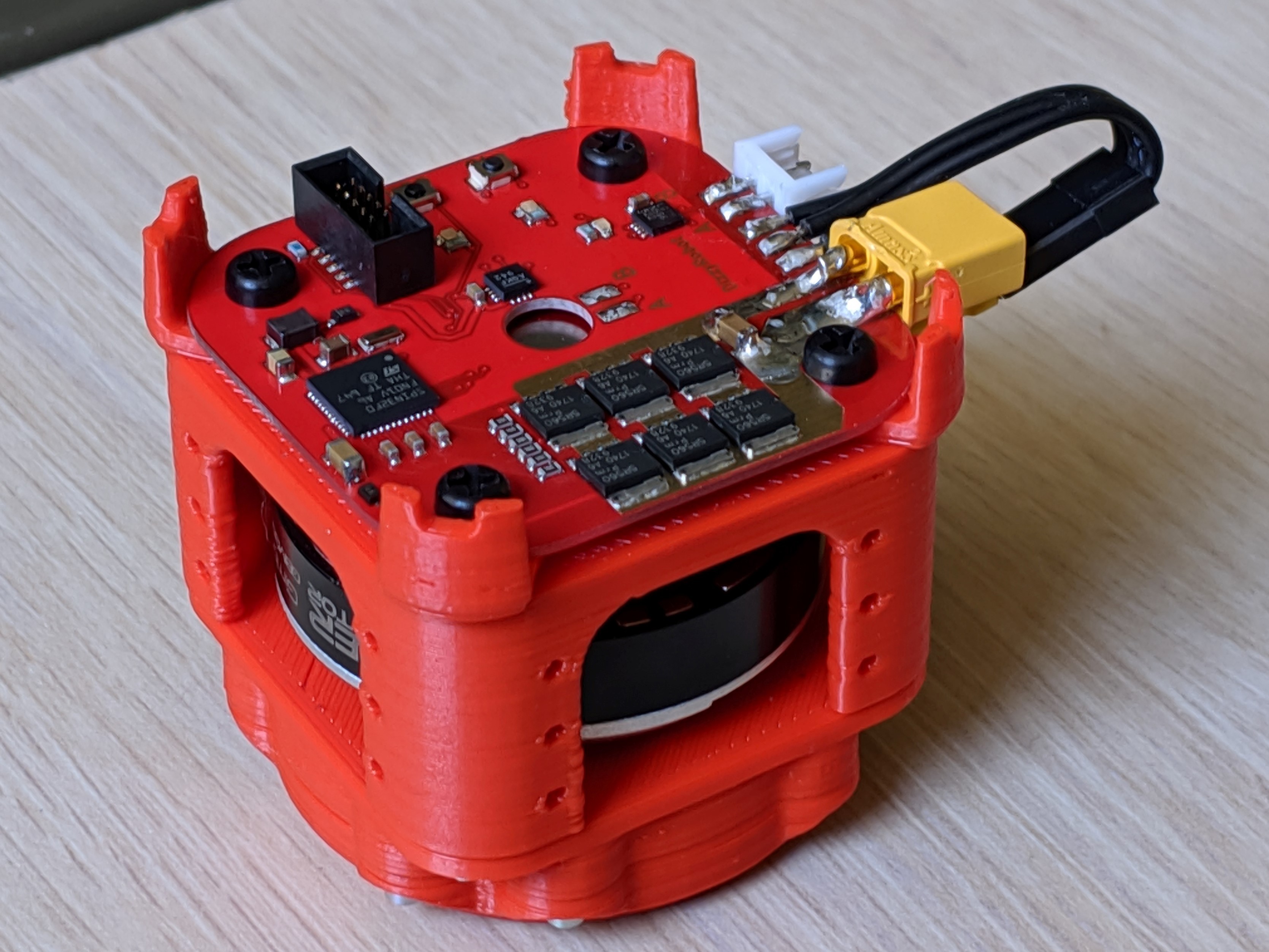
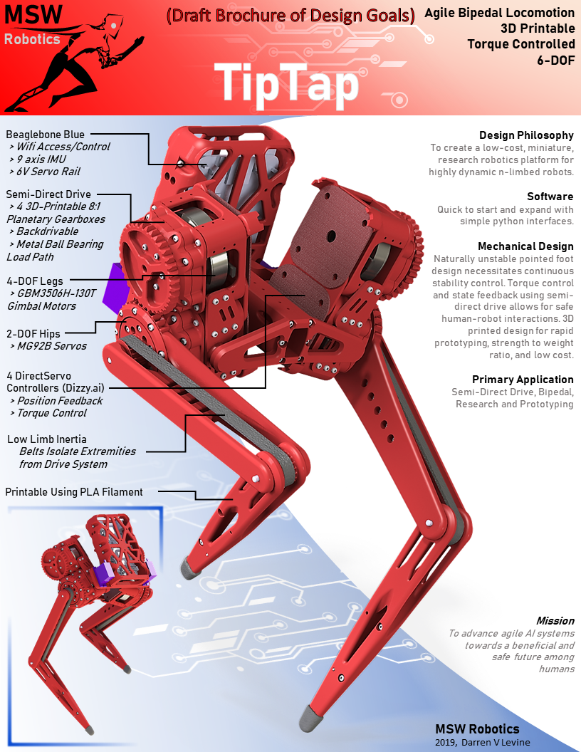
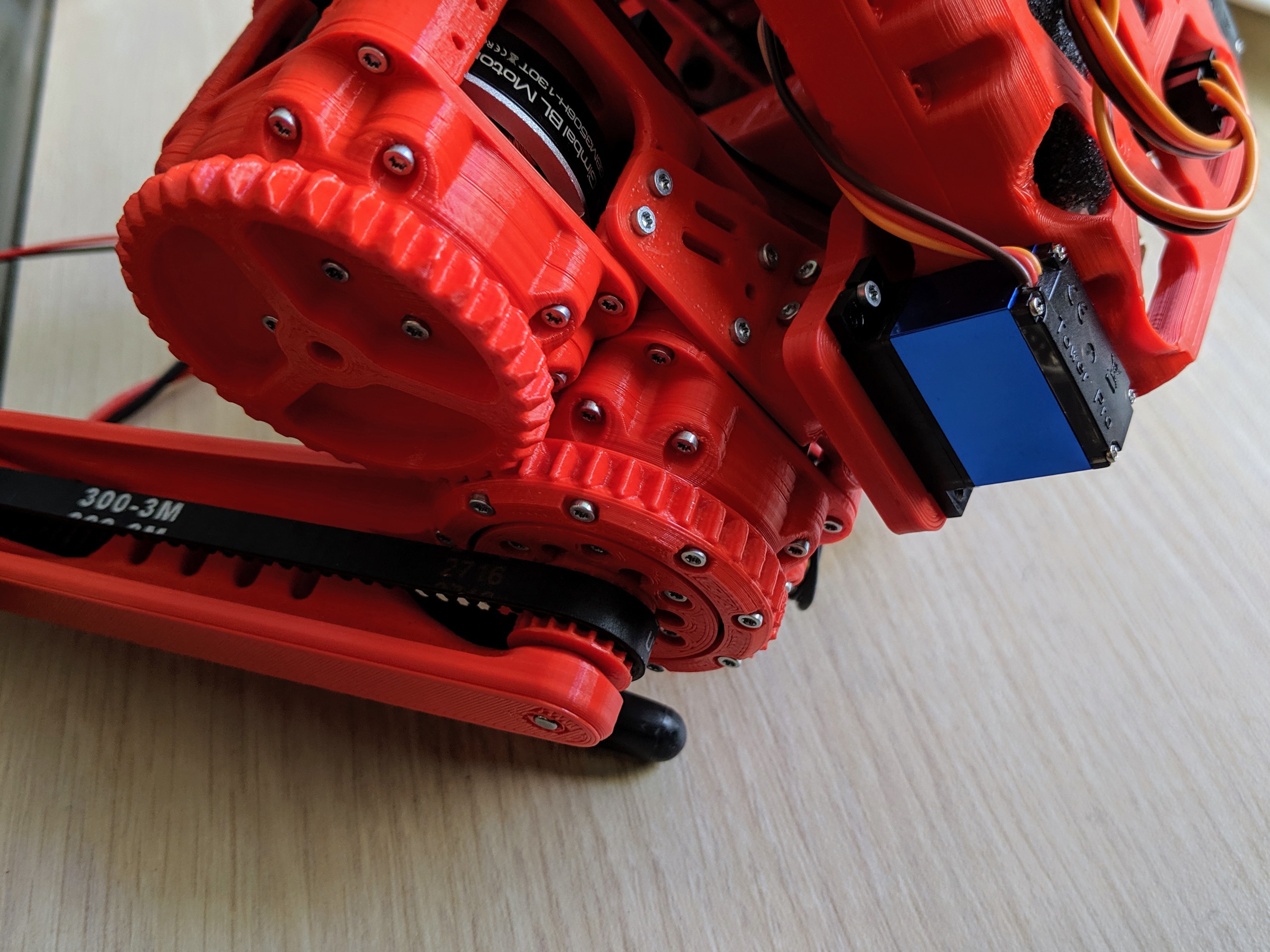
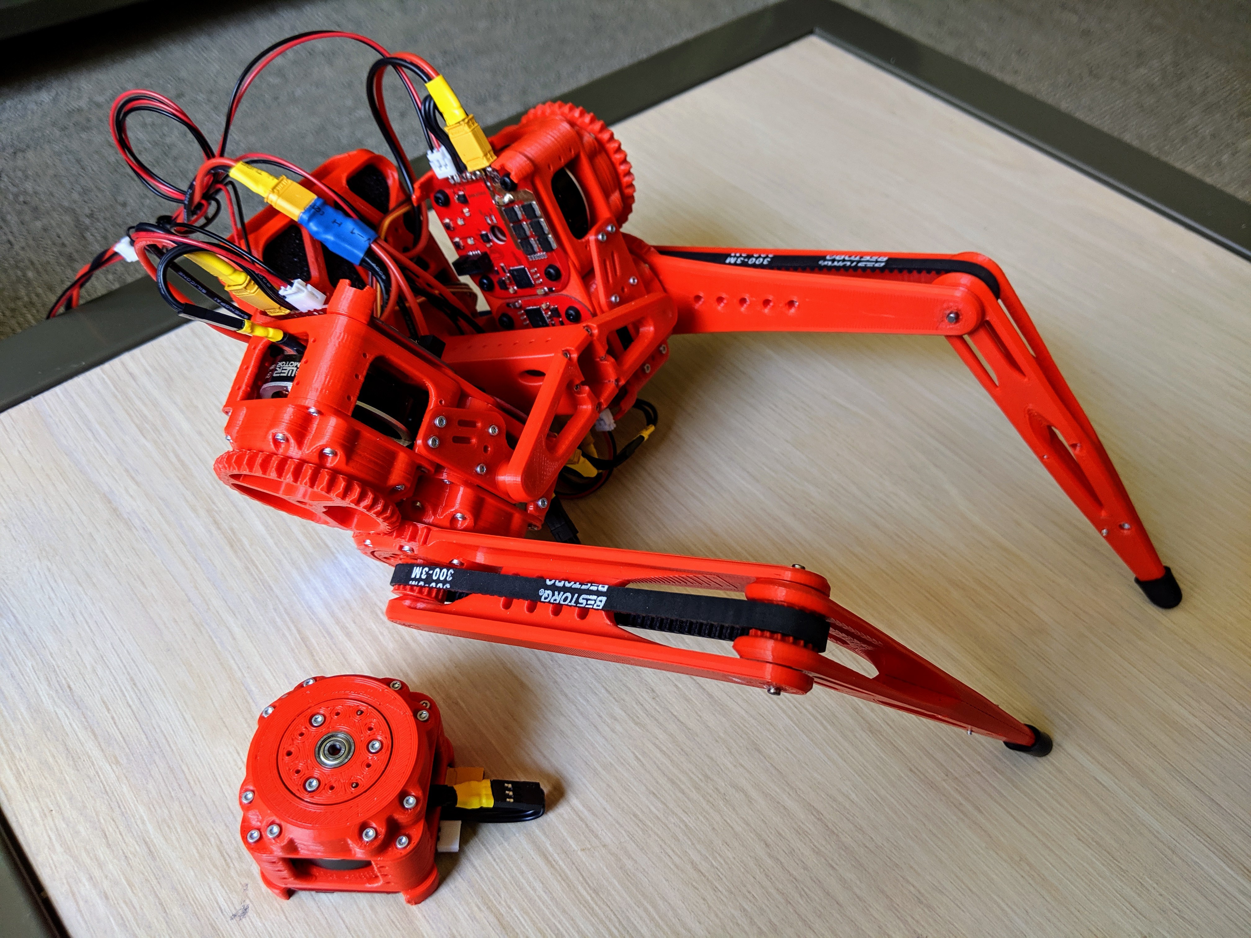
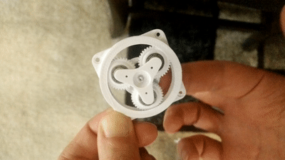
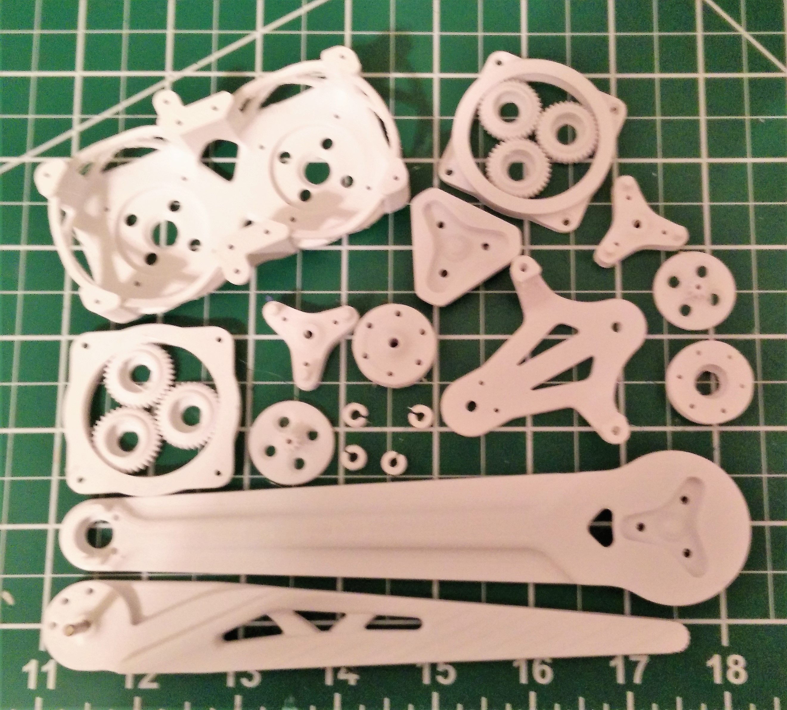
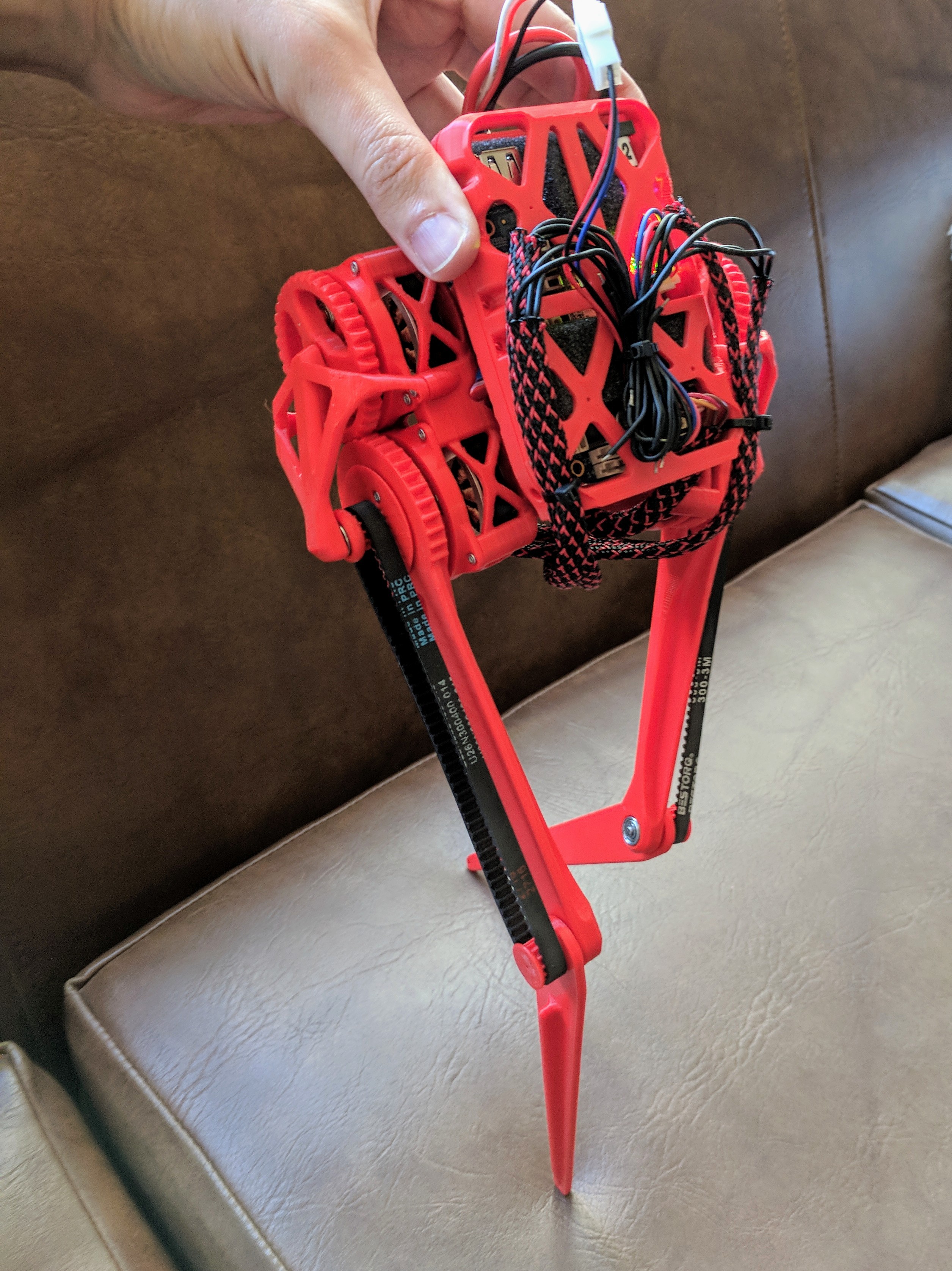
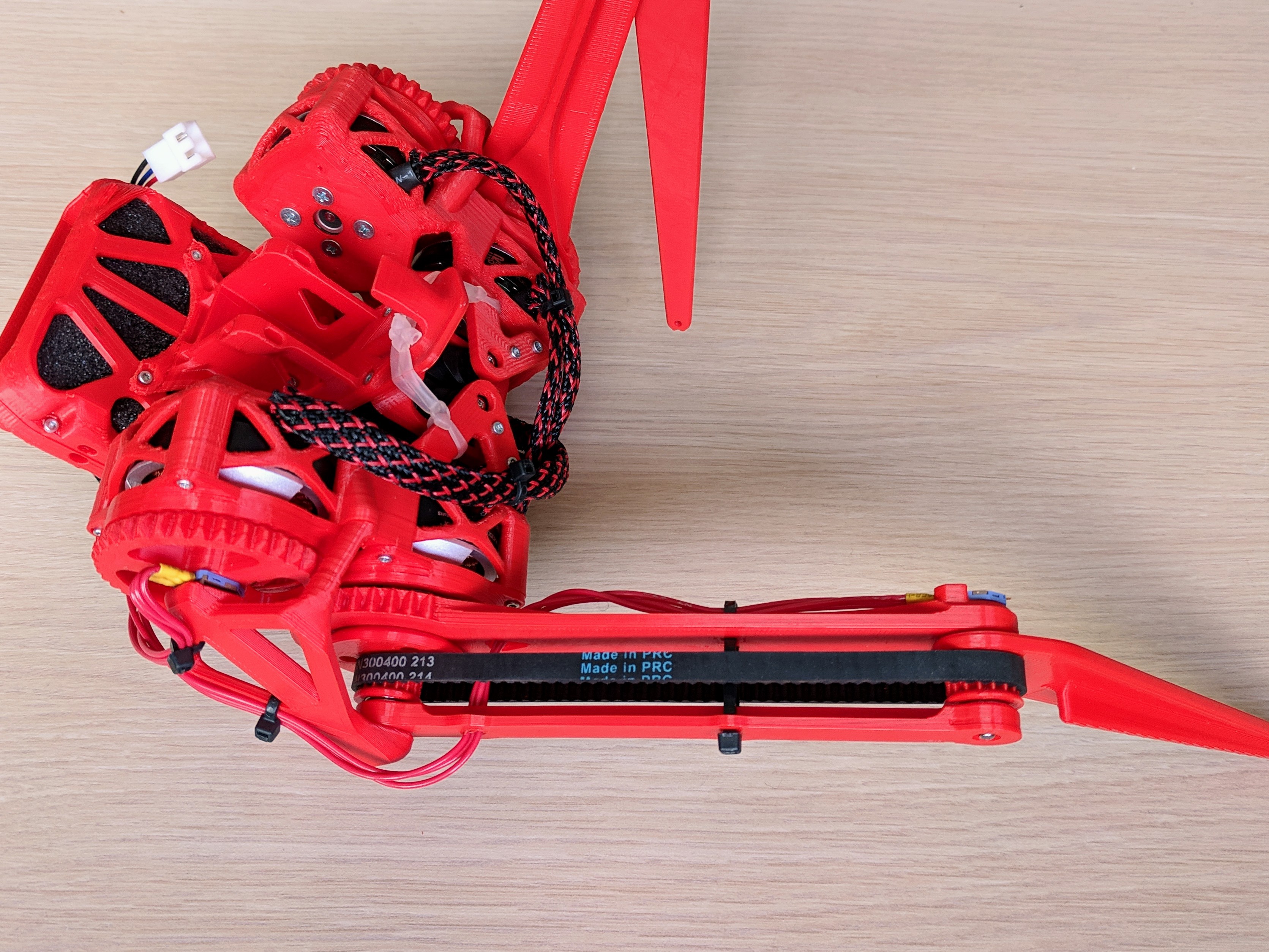
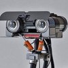
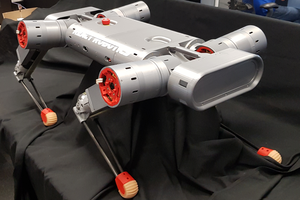
The platform is built upon a custom modular 3d-printed actuator, with a 8:1 planetary gearbox. The dimensions are 47mm x 47mm x 47mm, and the cost is about $74 per actuator. The BLDC controller board it uses is the DrizzyServo from dizzy.ai.


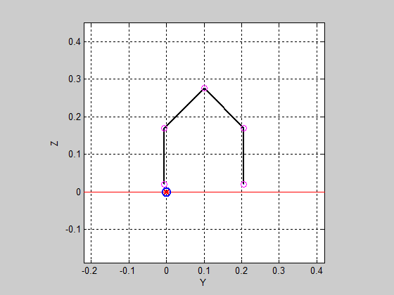
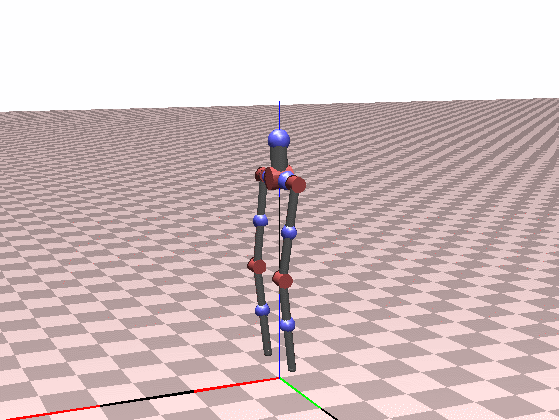
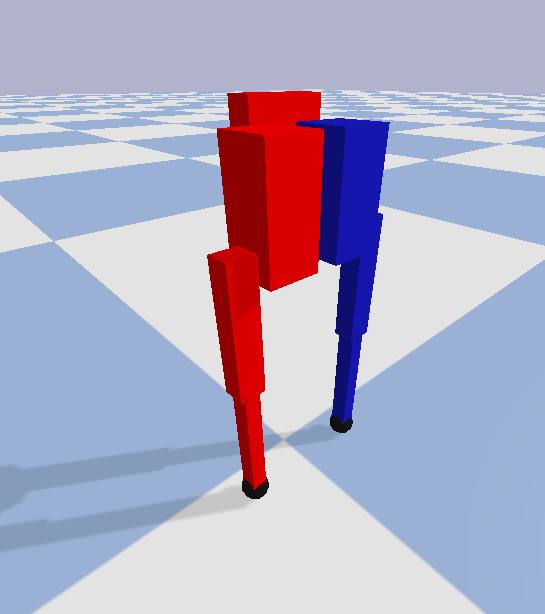
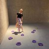
I also built a 2D Port-Hamiltonian and then later a 3D Featherstone simulation frameworks in MATLAB, in order to teach myself the low-level math/physics. Here are a couple simple heuristic based balancing controllers:
My design goals:


 David
David
 Nathan Peterson
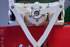
 Charles Galambos
Hi, I have a problem with the RS485 connection of the Direct Servo board, can you advise me?