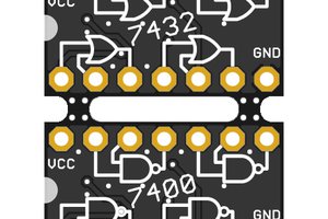
Logic gates are basic elements of digital integrated circuits.They act like the logical operators. The main logic gates are AND, NOT, OR.
Usually logic gates have two inputs and one output, except the NOT gate, which has one input.
The output of an AND gate is high when both inputs are high. An OR output is high when one or both inputs are high.
The NOT gate (also called inverter) reverses the logic signal.
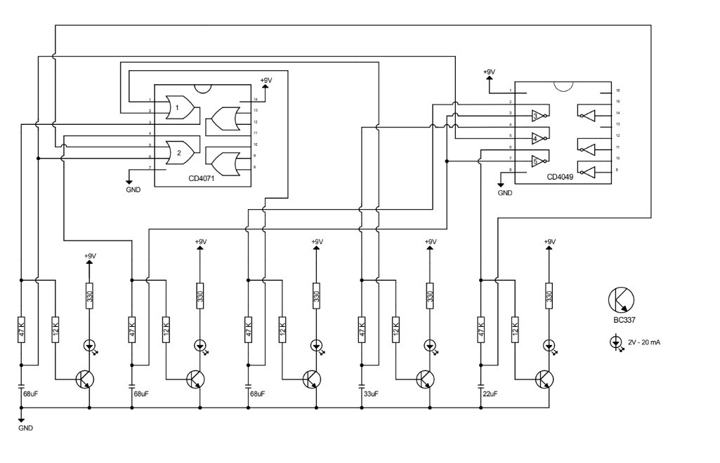
By connecting one or more logic gates in a certain manner, we can make a sort of flip-flop circuit. The one below works by OR and NOT gates and makes a strip of 5 led blink with an irregular sequence, as Christmas lights. Basically this is the working principle. Obviously a logic gates network blinks too much fast. For that reason I had to use capacitors.

 JRodrigo
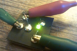
 Dr. Cockroach
 Al Williams
I like fun and different circuits such as this :-)