 bornach
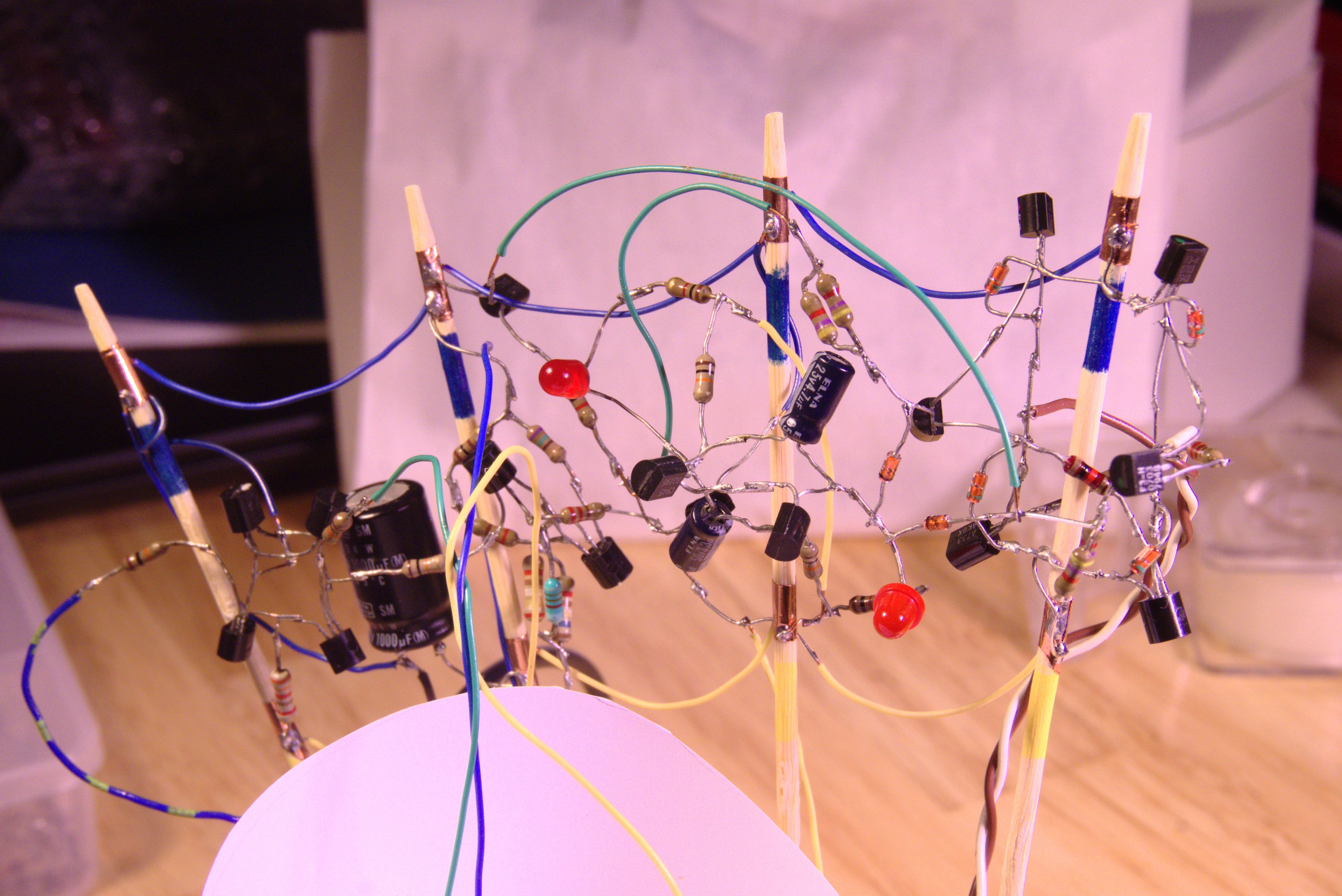
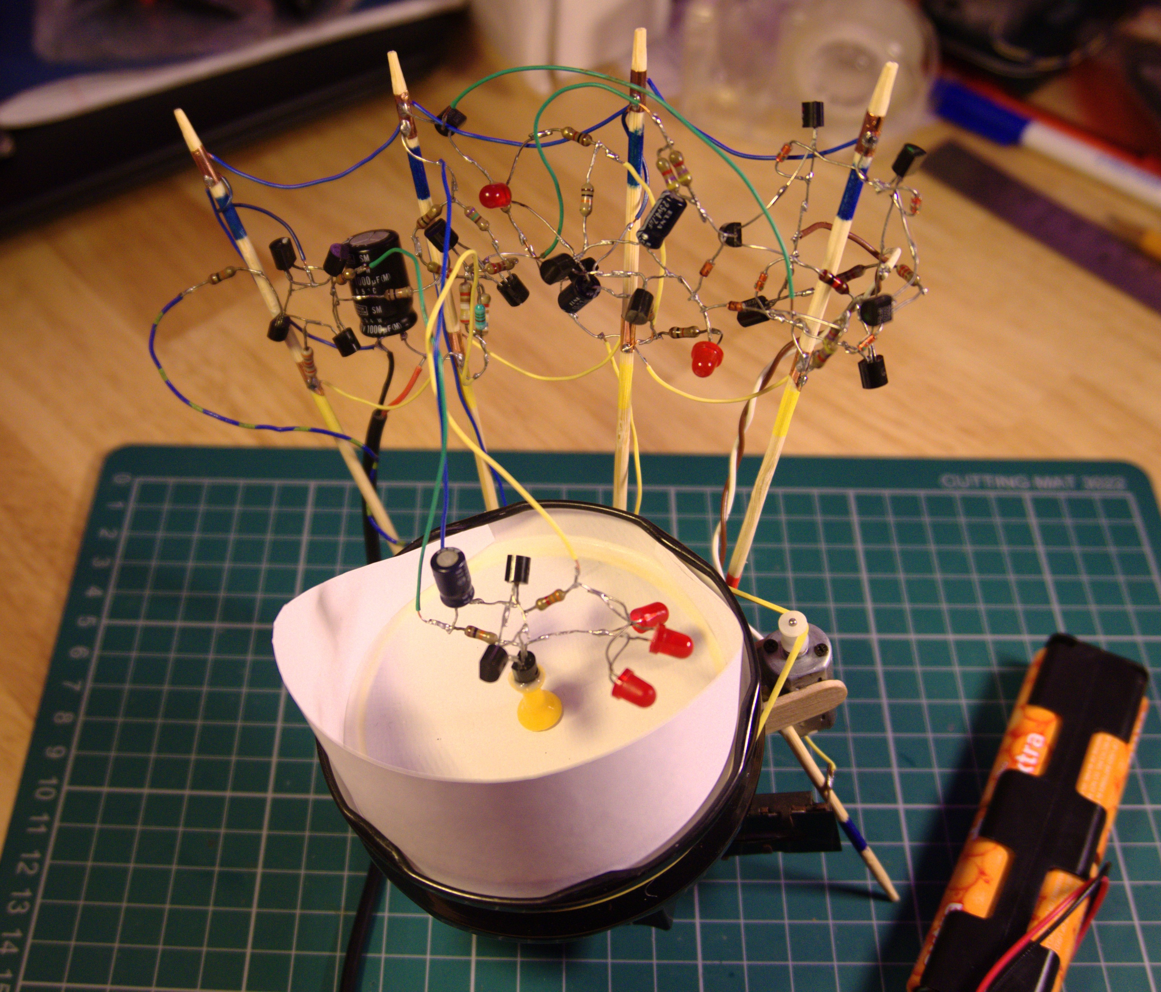
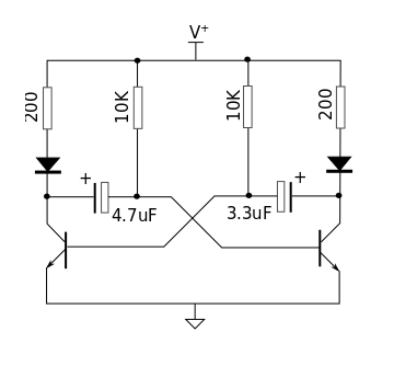
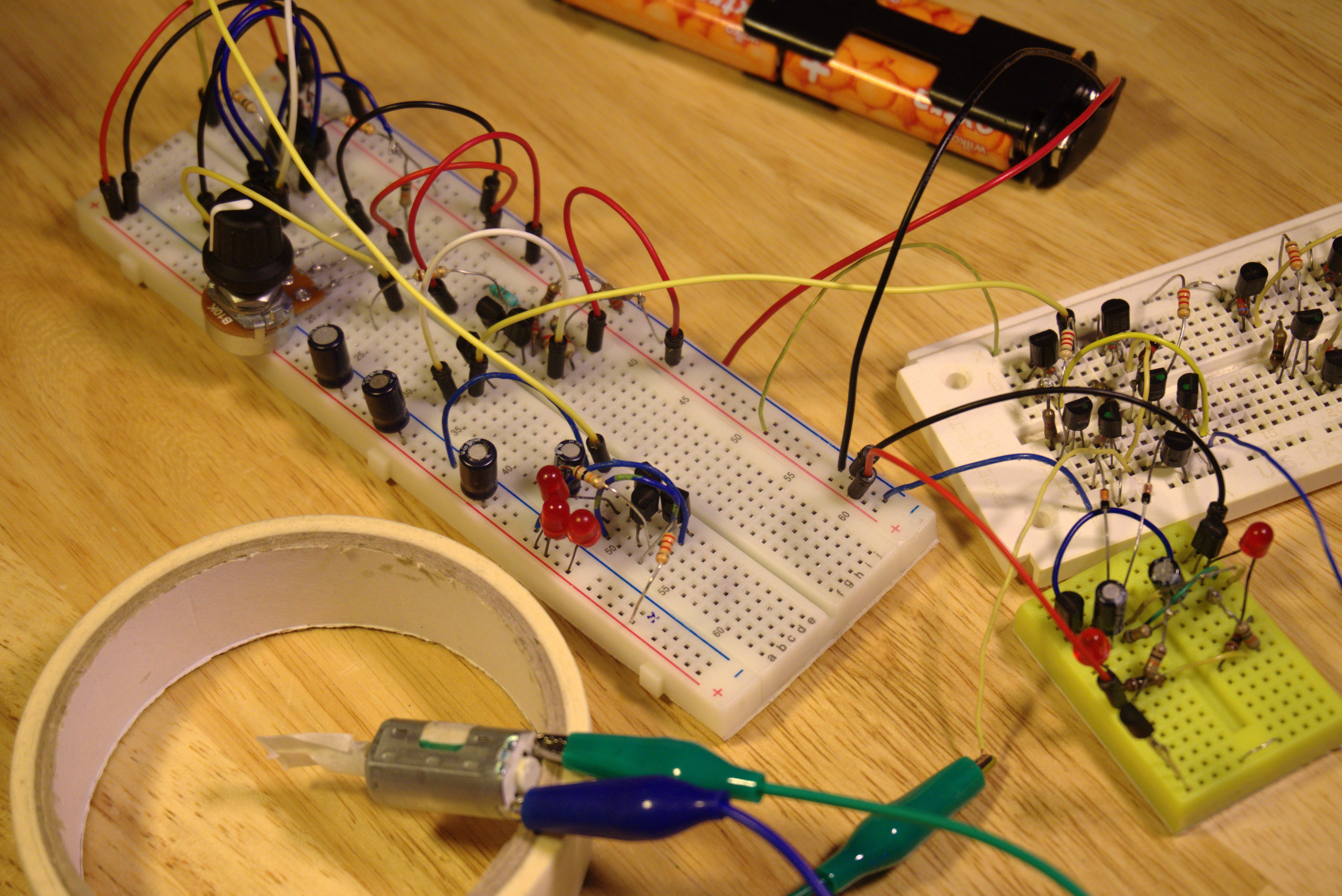
Admittedly the final circuit is a mess. As an excuse for my lack of effort at beautifying it, this is in keeping with the types of hacks my Dad would come up with - an emphasis on function over aesthetics.
His catch phrase was "This is just temporary".
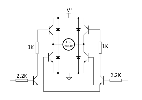
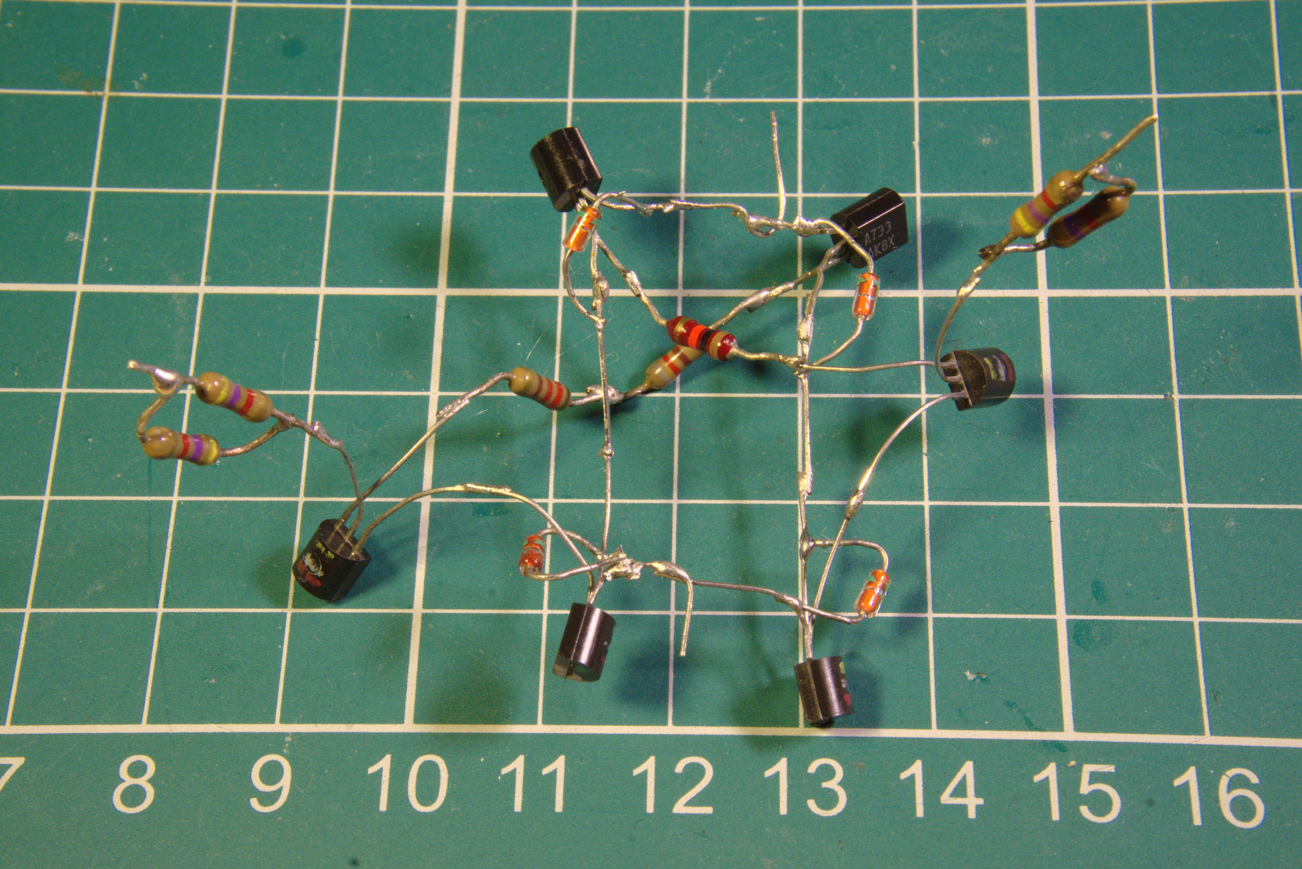
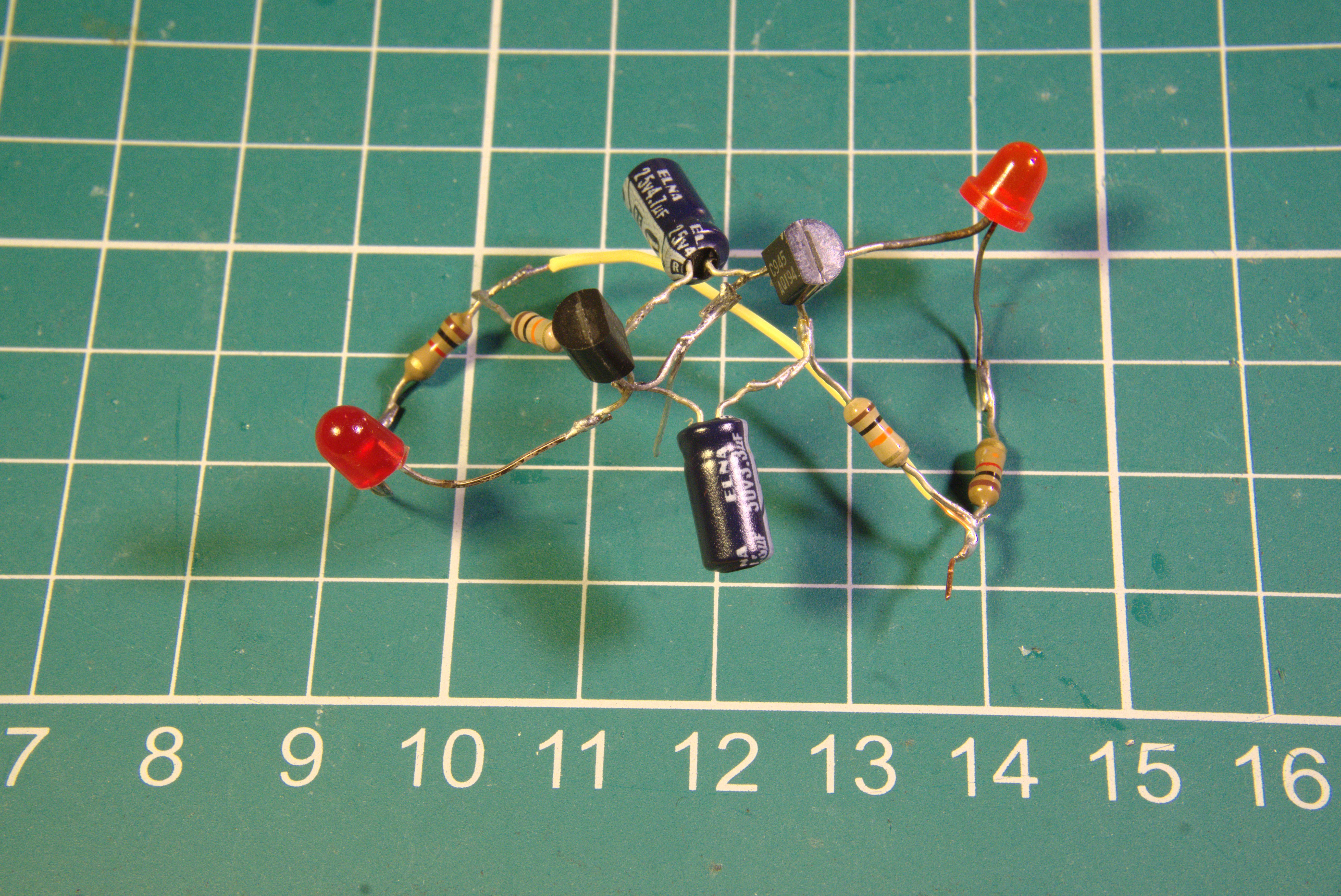
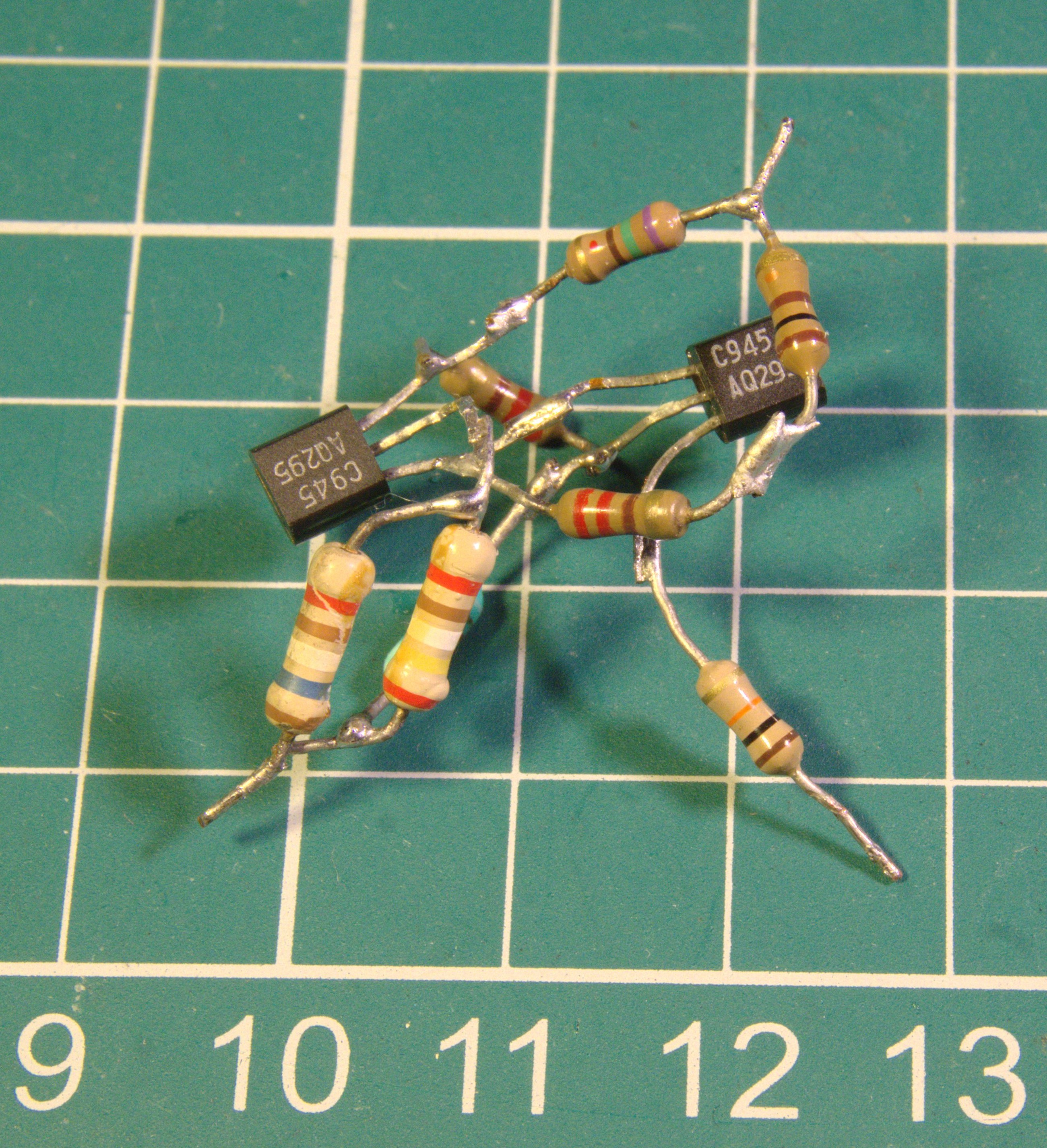
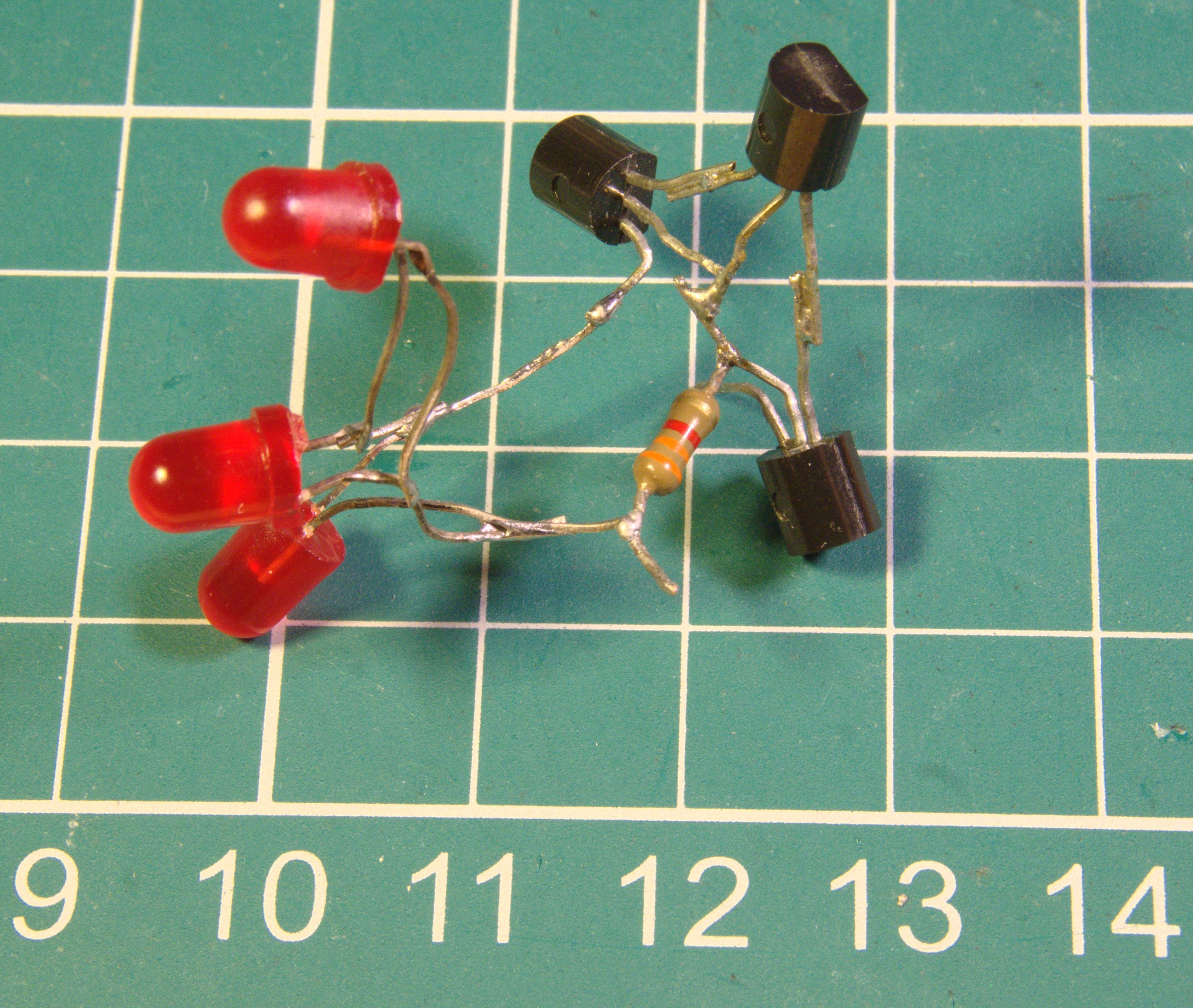
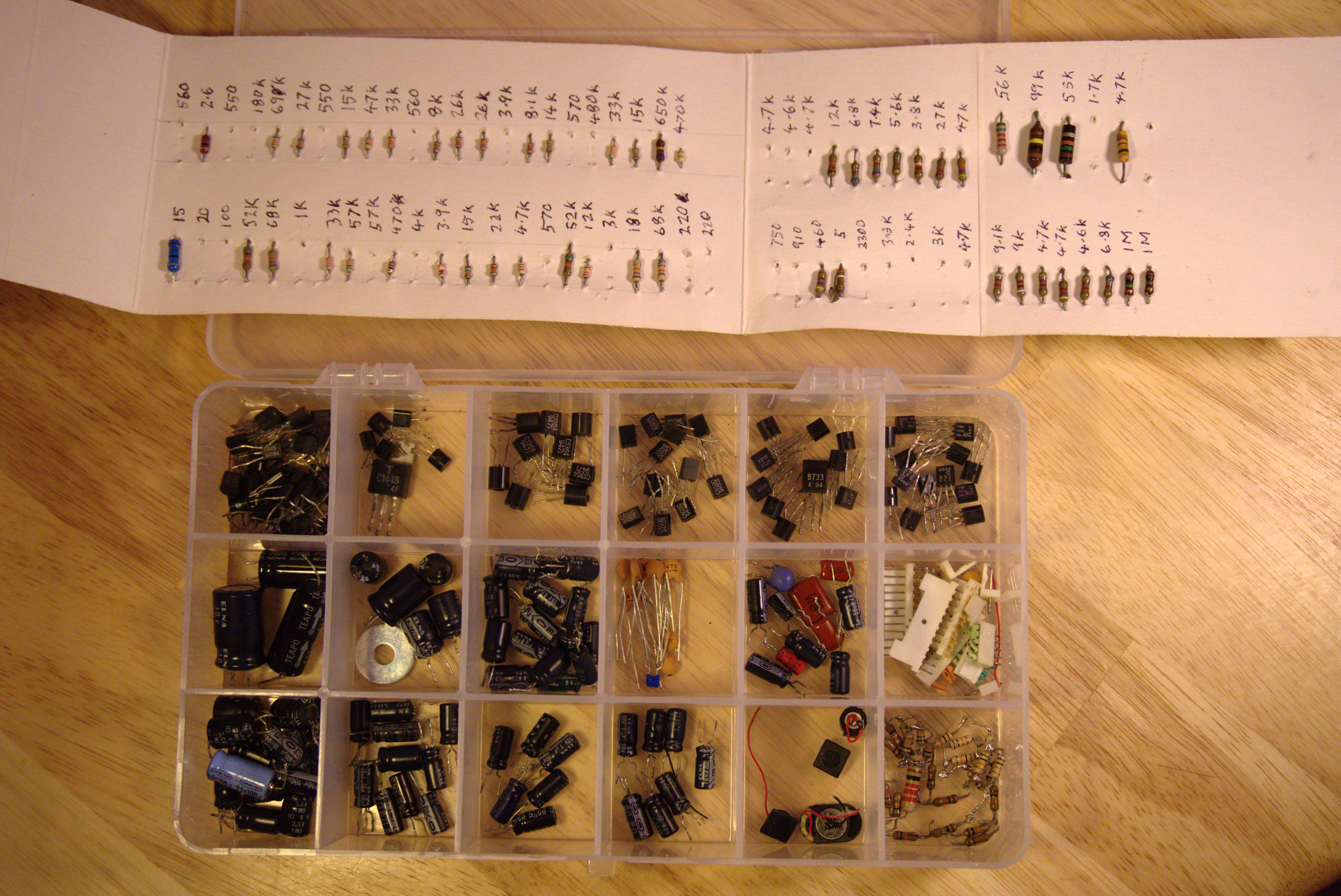
Note that there are no microcontrollers or integrated circuits of any kind. The kinetic movements are driven entirelly using recycled discrete electronic components.
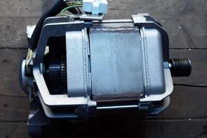
As explained in the video, I felt that the kinetic aspect was a necessary element. The types of hacks my Dad would create tended to be of an electro-mechanical nature rather than electronic. The improvised belt-drive using a DC motor from a tape player is in keeping with this tradition.
Please review the build log for more details on the prototyping and the design of the functional units that make up the final circuit sculpture.


 Andy Preston
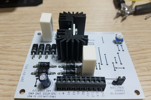
 Gabriel D'Espindula
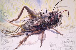
 Kelly Heaton
 ElectronicABC
That's a great tribute to your dad! I myself spent many hours in my youth harvesting components from dead electronics, so I can relate.
And function has its own beauty sometimes, right?