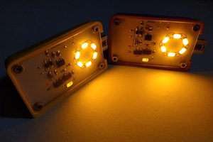
Using the ATtiny84a smallest development board (see my other projects) prototypes to create a spider. Since the Micronucleus bootloader was not working on these first prototypes, I decided to use these for something else. Even without the bootloader these little boards have all the other functions. Since I created these low-power consumption boards for projects with super capacitors, I came with this spider design where the super capacitor is used for the body. The legs are resistors and the eyes LED's. There are no current resistors on the LED's; the outputs are bitbanged instead. Even a small resistor will waste some of the energy.
Components
1×
ATtiny84 development board
See my other projects for more information
Dan asked in the comments how long the super capacitor keeps this all running. Unlike a battery, the super capacitor has no capacity rating since it works differently. A battery usually has a very consistent voltage till it runs empty, and when you know how much current you are using, you can get a very close guess on how long you can run based on that capacity.
Super capacitors use electrical capacitance in farad to determine the amount of energy it can store. Unlike the battery, the super capacitor will drop voltage when energy is used, so farad is used to calculate the amount of energy you can use per 1 volt drop.
The ATtiny is a great micro-controller with a wide operating voltage (1.8-5.5V), and powering a red LED, where the voltage forwarding is around 1.8V is a perfect fit. Super capacitors with a voltage rating up to 5.5V are widely available.
A capacitor is safe and you cannot overcharge (like with a battery), as long as you stay below the voltage rating. In this case we are going to charge up to 5V from a USB charger.
We could do a bunch of calculations, but we don't really know how much current the LED's are using. They are on for a fraction, and they change brightness all the the time. The current will also change when the voltage is changing. Instead I will use a stopwatch and multi-meter to measure the voltage.
Last time I charged the spider was 2 days ago and after connecting the multi-meter, it was showing 0.89V. I started the timer as soon as I connected the USB cable to the computer to charge the spider, with the following reading in the first minute:
Time (s):
Voltage (V):
0
0.89
20
4.56
40
4.61
60
4.80
I left it connected till the voltage no longer changed, 4.8V after 10 minutes. I have to determine later how short the actual charging time could be, it might depend on the charging cable and charger.
After disconnecting I started taking readings till it ran out, with the following results:
Time (H:mm:ss):
Voltage (V):
0:00:00
4.80
0:00:20
4.76
0:00:40
4.74
0:01:00
4.73
0:02:00
4.71
0:05:00
4.65
0:10:00
4.55
0:20:00
4.38
0:30:00
4.22
1:00:00
3.80
2:00:00
3.08
3:00:00
2.51
4:00:00
2.04
4:30:00
1.83
5:00:00
1.60
After 5 hours the micro-controller was still running. In an entirely dark room you can still see the LED flash, but just barely.
Upload the sketch using the Arduino UNO as SPI programmer. Use 1mm diameter pogo pins to connect to the board:
staticbyte timerDelay = 255;
bool timerDirectionUp = false;
voidsetup()
{
DDRA = 0xFF; // Set all pins on PORT A to outputs
PORTA = 0x00; // Set all outputs to LOW
DDRB = 0x0F; // Set all pins on PORT B to outputs
PORTB = 0x00; // Set all outputs to LOW
cli();
TCCR1A = 0; // Timer/Counter Control Registers
TCCR1B = 0; // Timer/Counter Control Registers
TCNT1 = 0; // Timer Counter//OCR1A = 3906; // Output Compare Registers 0.256 * 3906 = 1000ms
OCR1A = 30;
TCCR1B |= (1 << WGM12); // Clear Time and Compare CTC
TCCR1B |= (1 << CS12); // 256 prescaler 1Mhz/256 = 0.256ms
TIMSK1 |= (1 << OCIE1A); // Output Compare A Match Interrupt Enable
sei();
}
ISR(TIM1_COMPA_vect) // timer interrupt
{
if(timerDirectionUp)
{
timerDelay++;
if (timerDelay > 200) timerDirectionUp=false;
}
else
{
timerDelay--;
if (timerDelay < 5) timerDirectionUp=true;
}
}
voidloop()
{
cli () ; // Turn off interupt
PORTA |= (1<<0); // set pin 0 (PA0) to HIGH
__asm__("nop\n\t"); // Wait for 1 clock cycle
PORTA &= ~(1<<0); // set pin 0 to LOW
PORTB |= (1<<3); // set pin 11 (PB3) to HIGH
__asm__("nop\n\t"); // Wait for 1 clock cycle
PORTB &= ~(1<<3); // set pin 11 to LOW
sei () ; // Turn on interupt
delayMicroseconds(timerDelay*10);
}
After uploading the sketch, disable the reset fuse in CMD (find your settings in the Arduino verbose output):
I picked pin 0 and 11 since these are the closest to the USB connector (head of the spider) after the 5V and GND. 5V and GND are used for the first legs. Unfortunately pin 11 is the reset pin and for that reason the reset was disabled in step 1 so that it can be used as an output.
3
Solder the legs
Solder the resistor, sticking out from the top on pins 5V, GND, 1, 3, 5, 6, 8 and 10.
At least of couple of hours. It was still going when I went to bed, but had no more power in the morning. I will use a stopwatch tonight and share the results in a log. I also have to determine how long it takes to charge, should only take a couple of minutes.
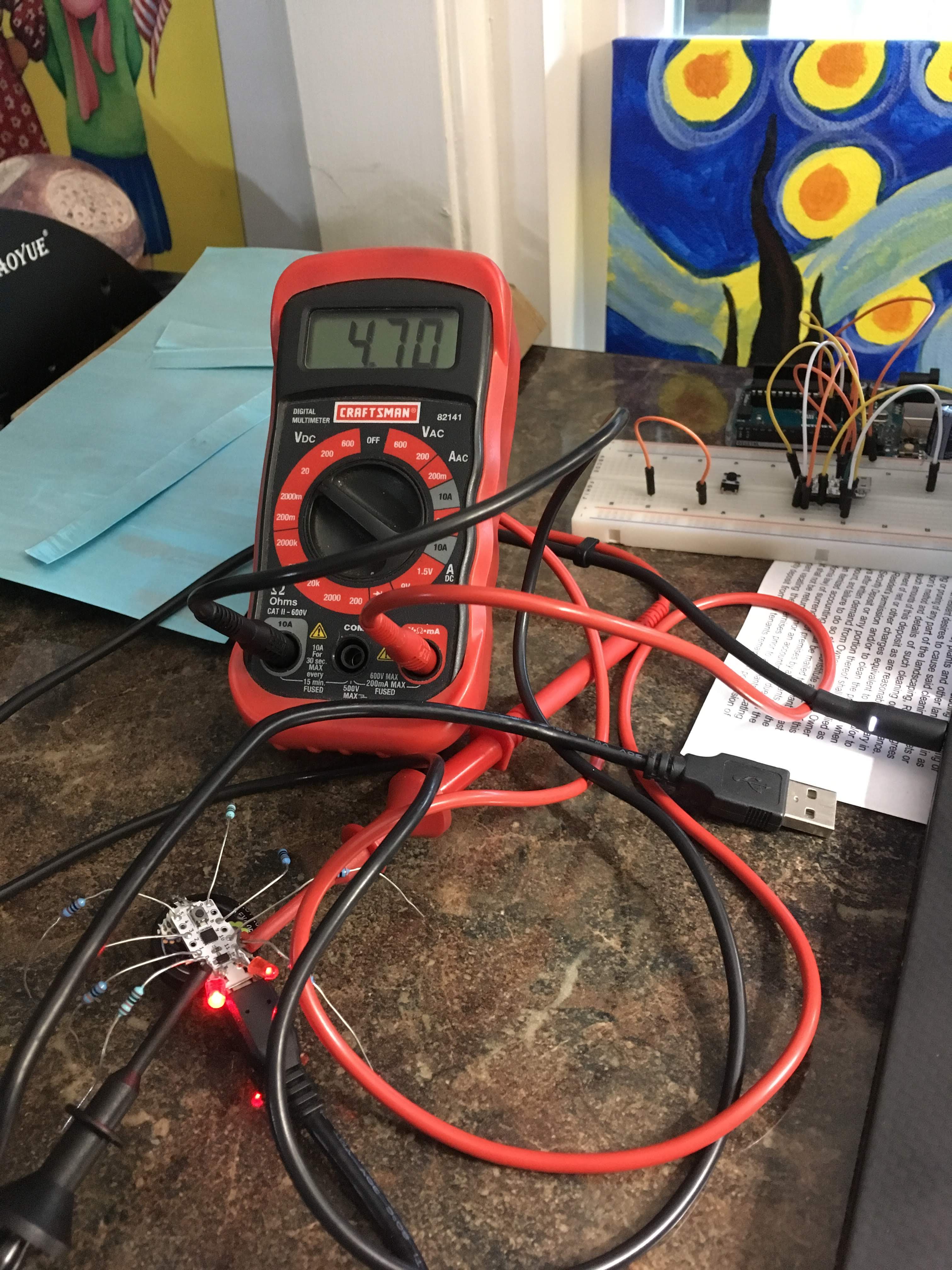
This is nice project for me. I thought it would move but just the LED flashed.
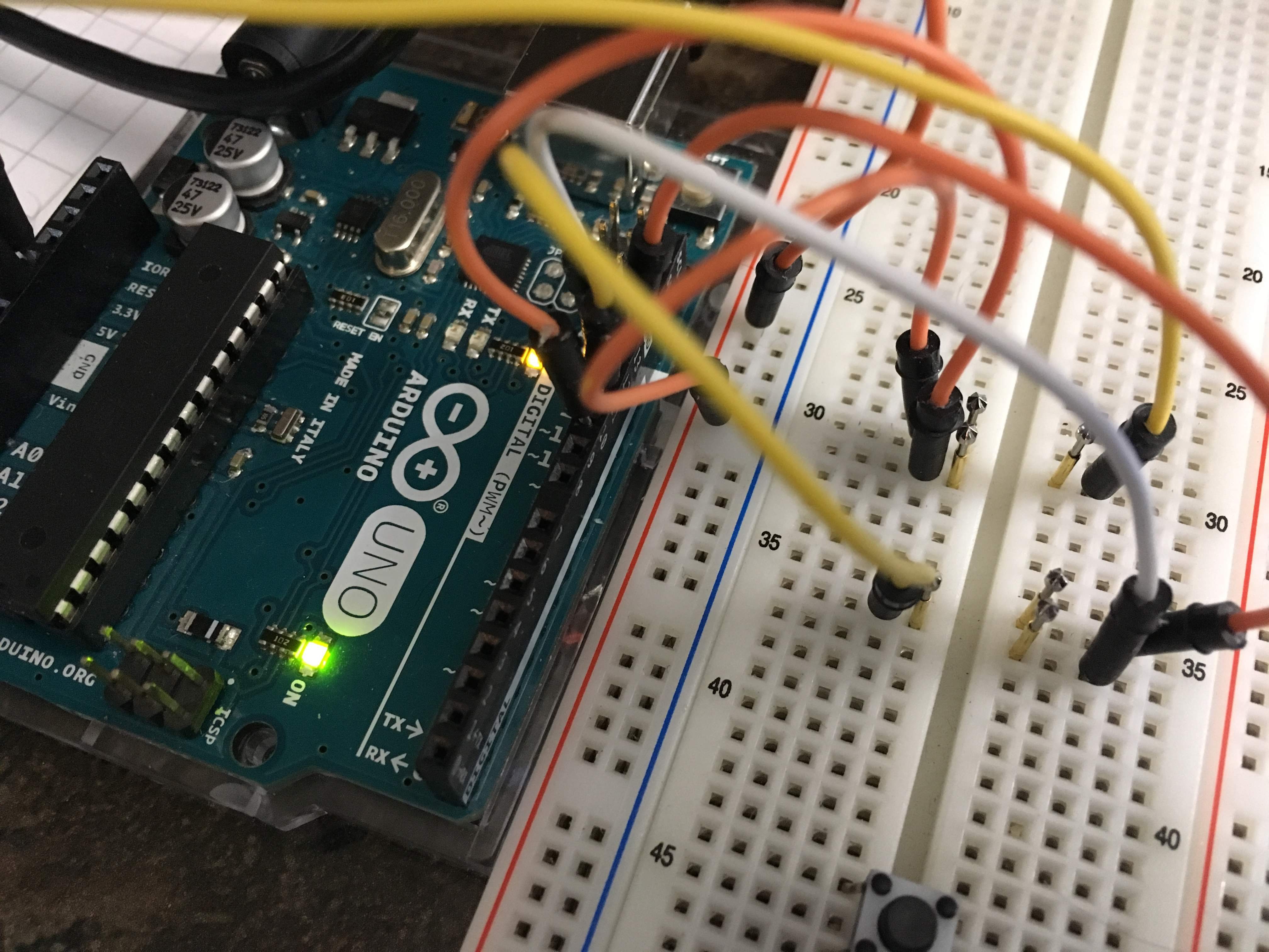
That's first step. See the sketch like Arduino code. I try It, many many compiling error.
Is it that sketch compiling in Arduino IDE? My environment is Arduino 1.8.19. and installed
Spence konde's megaTinyCore.