 John
JohnThe first problem to overcome is what chip (IC) to use to measure voltage and current. Other products out there use analog to digital (ADC) ICs, record the data, and then do some math on an MCU to spit out some numbers that make sense. That same MCU probably uploads the data to something via wifi.
The problem with this approach is the bottleneck with communicating between multiple ADC ICs, usually on a single SPI or I2C bus, while calculating the current and voltage. Depending on the amount of channels that you want to measure, and how many channels the ICs can handle determines how many ICs are actually used. One IC with 8 channels will definitely cost more than one with 4, but having two 4 channel ICs may be more complex and slow down the transfer of data. So maybe the one IC with 8 channels is worth the cost. Regardless, the MCU still has to to interpret and calculate all of the incoming data. This is fine if you're not looking for near real time energy metering.
The ESP32 is probably capable of handling all of these calculations while handling the communication between the ICs, then uploading the data to something via wifi - especially the dual core version. Honestly, I didn't want to find out. The software around actually using both cores isn't mature, and there are already a lot of ESP32 dev kits out there that use the single core ESP32 IC. Besides, I already know the capabilities of a purpose made energy metering IC when the MCU is only responsible for getting data from the IC, and communication.
So, if you can't tell, I don't want to use a plain old ADC to do this. Purpose built energy metering ICs seem like a more practical solution. However, that brings up another problem. A single energy metering IC that can read multiple current channels (>3) does not exist. Okay, there's one made by Analog Devices that can do 6 current channels / 1 voltage, but it's pretty expensive ($5.70 each for 2,500 up to $10.47 for 1, currently). Even if I wanted to use this IC, it's not stocked in large quantities.
Purpose built energy metering IC:
Advantages:
- Fast & nearly real time
- Higher resolution (16 bit)
- Includes temperature sensor to compensate for temperature drift
- Pulse output
- Calculates Vrms, Irms, mean active/ reactive/ apparent power, frequency, power factor and phase angle.
- Less complex software to calculate energy usage
Disadvantages:
- Less current channels available per IC
- Cost is sometimes higher
To solve the problem of not having enough current channels, why not make the design modular? Since there seems to be a wide range of circuits (from about 3 to their whole breaker box) that people want to monitor anyway, this would make sense. It would also decrease the cost by not having to make multiple products with different current values. For example, Product A with 6 channels, Product B with 12 channels, Product C with 24 channels.
With a modular setup the user can buy a "motherboard", then purchase as many "daughterboards" as they need up to a certain amount. In this case that limit is determined by the number of available GPIOs available for Chip Select or CS (or SS) assignment on the ESP32 (more on this later). Then the ESP32 would plug in on the top of the
We can still use a much less expensive 3 channel energy meter IC to do the work, like the Microchip (Atmel) ATM90E32 that was used in the 2-channel energy meter. It actually has 6 ADC channels, 3 for voltage, 3 for current. This is because it is built for 3-phase energy metering. Luckily, its channels can be turned on/off and/or mapped in software and configured in different ways. Unfortunately, you can't use those voltage channels as current channels. Since it is so cheap ($1.75/pc) compared to every other one available out there, including regular old 4 channel ADCs, it is worth it.
Here is the first iteration with 3 current channels and 2 voltage:
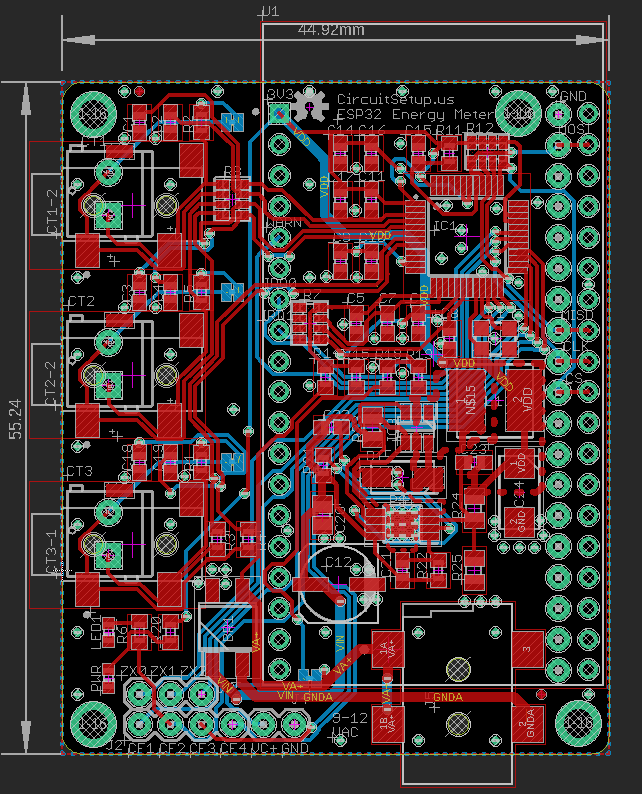
The DC Jack is where the AC Transformer is hooked up. The voltage sample for VA+ is taken here, and is tied to VC+ by default. The user can sever this connection and use VC+ to measure a secondary voltage. The AC signal is run through a bridge rectifier, a large capacitor, then a 3.3V 2A output buck converter.
For the current measurements, there are footprints for a 3.5mm jack or a screw connector. The user has the option to use the on-board burden resistor (default) or sever the connection in their current transformer has one built in.
Discussions
Become a Hackaday.io Member
Create an account to leave a comment. Already have an account? Log In.