The CC2531 is a complete ZigBee / IEEE 802.15.4 transceiver bundled with an 8051 CPU and an USB interface on one chip. You can get these for a few dollars from aliexpress or ebay. Since it has a programming port, you can upload/install a custom firmware which acts as a zigbee concentrator.
Once you have the correct firmware installed, you can use it to replace most if not all of your proprietary ZigBee gateways and use it to control a variety of different devices, such as lamps, temperature sensors, switches, etc.
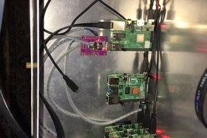
Depending on your home automation system, you can either use the stick directly with an appropriate adapter or have it plugged into a raspberry pi (or orange pi, etc. ) and use it as remote ZigBee to MQTT gateway which can be placed in a suitable location in order to get a better range.
Once you have your stick up and running, see also my other project on how to add an antenna socket for increased range: CC2531 USB Adapter Antenna mod
[2019-01-29] update: new Z-Stack-Firmware with group support and increased stability from Kkoenk available: https://github.com/Koenkk/Z-Stack-firmware/tree/master/coordinator/CC2531

 CarbonCycle
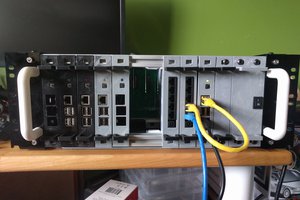
 Ben
Ben
 helge
helge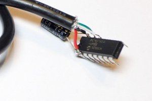
 Colin O'Flynn
can i do this with a raspberry pi 4b 8gb as well?