0%
0%
Micro RC Car Teardown
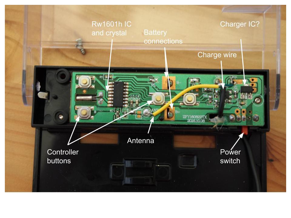
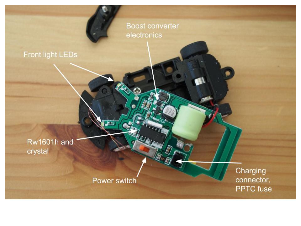
Teardown and analysis of the PCB in a Rocket Racers micro "pop-can" car
Become a Hackaday.io member
Already have an account? Log in.
Just one more thing
To make the experience fit your profile, pick a username and tell us what interests you.
Pick an awesome username
hackaday.io/
Your profile's URL: hackaday.io/username. Max 25 alphanumeric characters.
Pick a few interests
Projects that share your interests
People that share your interests

 Duane Degn
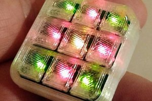
 Andrey Kalmatskiy
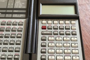
 tomcircuit
 makeTVee
Hey thanks for the note. On mine the only writing on it is "+80P" I think (even that is partially occluded by the PCB.) I think you are correct though, I am adding a teardown log of the controller, with a discussion of why I thought it might be a supercap. Mainly it is because I didn't see any charger electronics, although maybe with such a low cost device they are doing a much simpler CV charging method.