Close
0%
0%

Seismometer

An inexpensive Lacoste pendulum seismometer

Similar projects worth following
A relatively inexpensive ($150) seismometer that can (mostly) be assembled using parts from the local hardware store. It is quite sensitive: can detect movement below 30nm in the range of 0.05Hz to 0.5Hz. Will pick up a 6 magnitude quake anywhere in the world and smaller quakes (3-4 magnitude) closer to home.

This seismometer has been running 24/7 for the past 3.5 years. It's time to document it and also upgrade the sensor to a professional-level PCB instead of a chicken scratched monstrosity. This space will slowly accumulate all of the information necessary to build one.

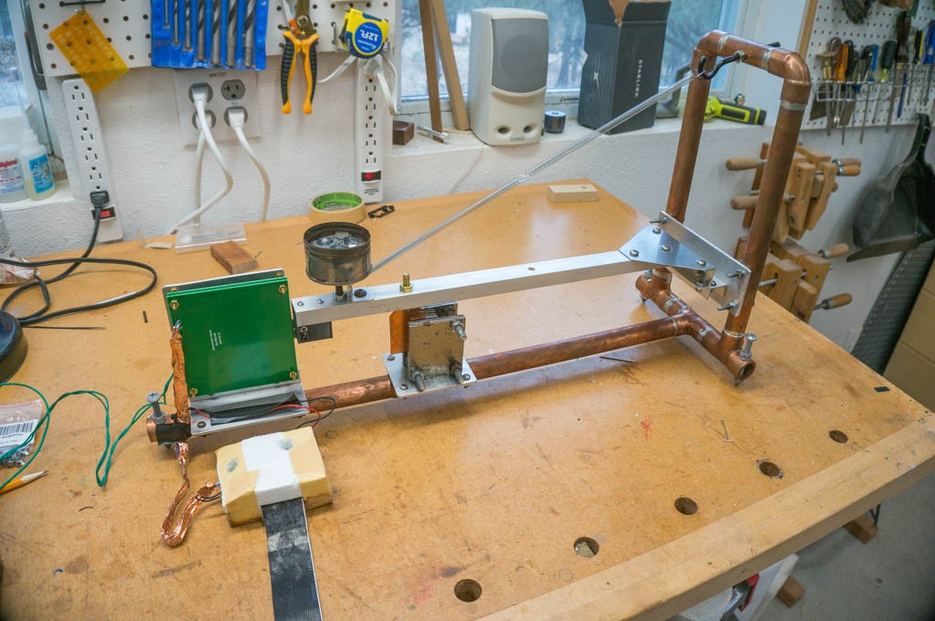
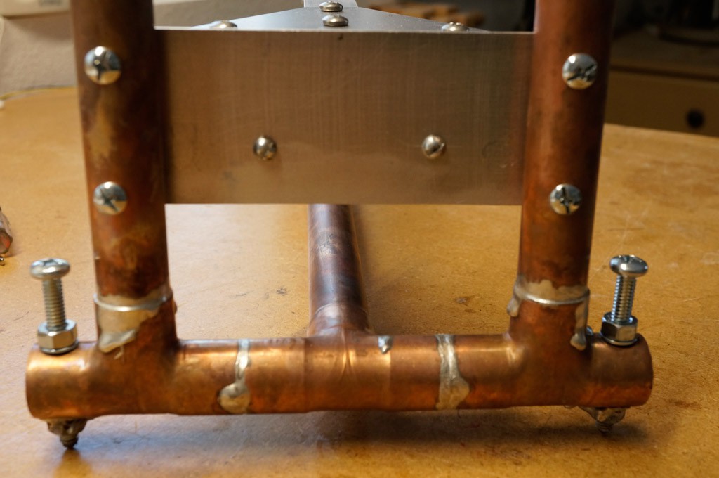
It started out as a wooden prototype, to keep the cost low, but morphed into a relatively easy to build frame made from copper tubing from the plumbing section of the local hardware store. 

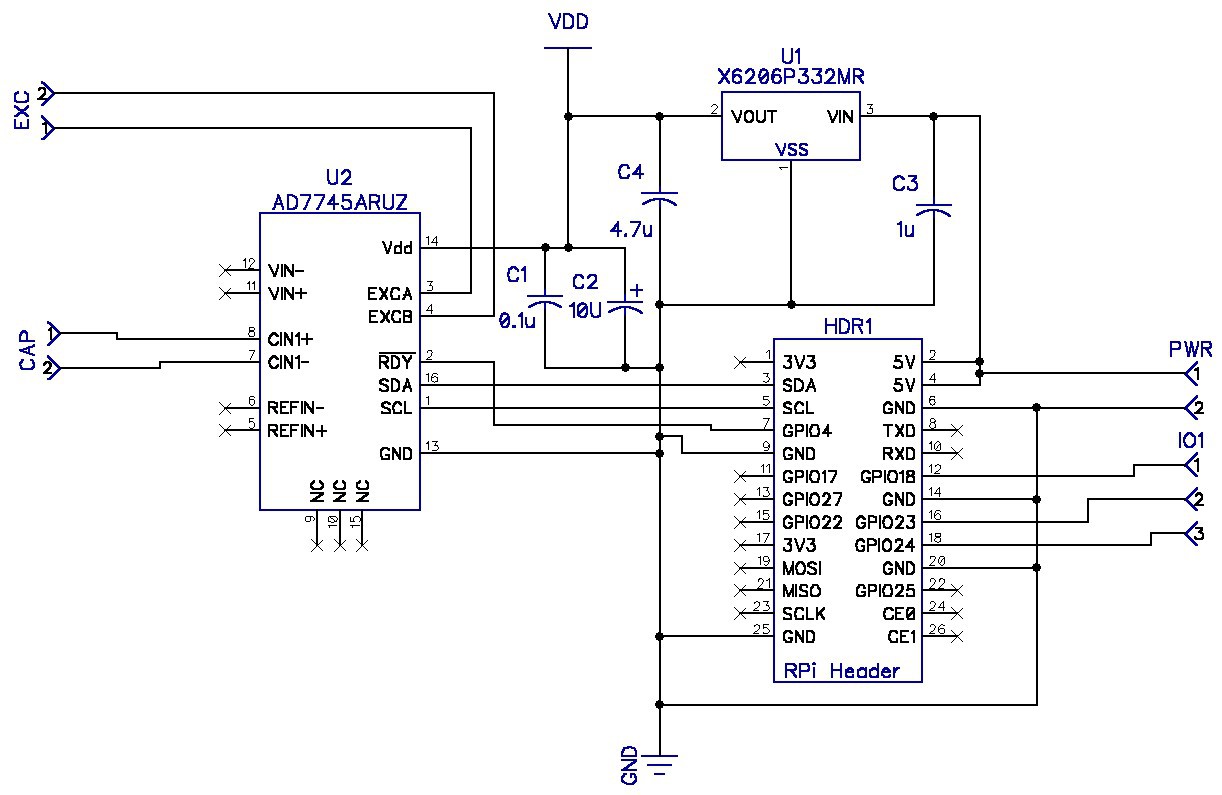
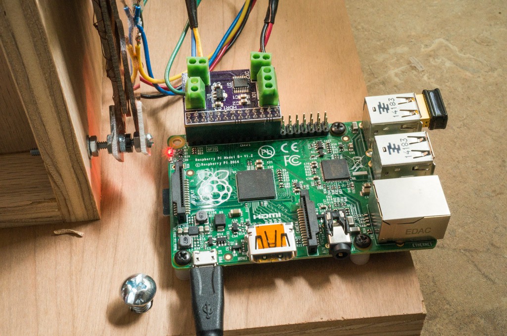
It uses a home-made capacitance displacement sensor to sense the movement of the pendulum. The electronics employ a 24-bit capacitance-to-digital converter and a basic Raspberry Pi single-board computer.

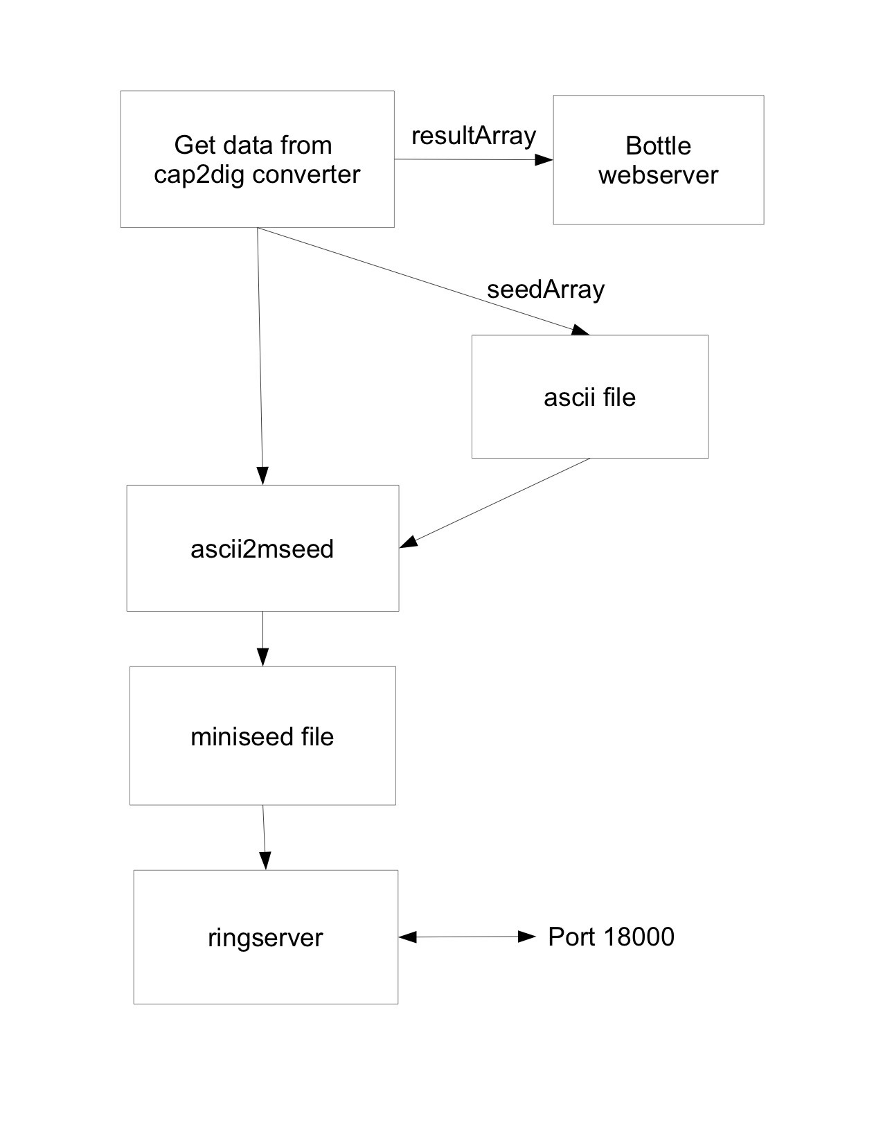
The Raspberry Pi provides a ringserver function on an ethernet port so the seismometer data is available to any computer running standard seismic data collection software.

This is a hobbyist-level seismometer. Professional grade units start at $1500 and usually must be buried at least 15 meters (40 feet) underground to avoid temperature swings and surface disturbances (like wind through the trees.)

Some Background Information:

An excellent overview is presented in this paper: Havskov, J., "Instrumentation in Earthquake Seismology", June 2002. (Available in the files section of this project.)

The basic concept is a mass suspended from a spring, with some method of measuring the displacement caused when the ground moves relative to the mass, which is supposed to remain stationary. All of the diagrams below are from Havskov paper.

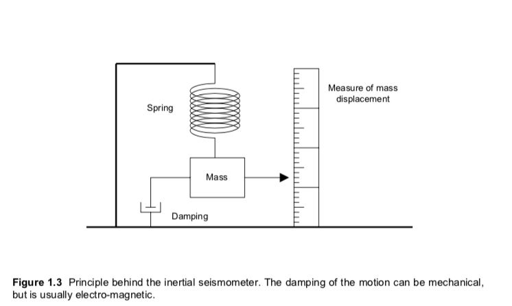
The system must be damped to remove the resonance at the natural frequency of the pendulum. Otherwise, the response tends to "ring" at the natural frequency when perturbed. The seismometer above measures movement in the vertical axis (the z-axis). Many hobbyist level seismometers only measure movement in the x or y direction, and require two seismometers to get both dimensions. Most professional seismometers measure movement in 3 dimensions, x-y-z. My preference was to detect vertical movement for two reasons: it can be less sensitive to certain noise components, and it has no preference to east-west or north-south orientation.

These are the frequencies of interest to seismology:

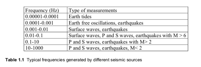
It would be nice if the seismometer could measure frequencies over the range 0.001 Hz to 10 Hz -- a 4 decade range. The problem is that the pendulum system has to have a very low natural frequency in order to be sensitive to very low frequencies. Long period seismometers are difficult to make stable -- a 30 second period is usually the limit of what can be obtained easily, with a reasonably long pendulum. Here's a series of plots showing frequency response of various sensor types coupled with the natural frequency of the pendulum.

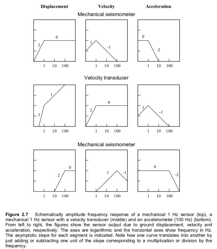
A velocity sensor response falls off at the rate of 60dB/decade below the seismometer's natural frequency. A displacement sensor is a bit better -- only 40dB/decade. All things being equal...using a displacement sensor to measure movement should result in a seismometer with a decade lower frequency sensitivity.

Lacoste Pendulum:

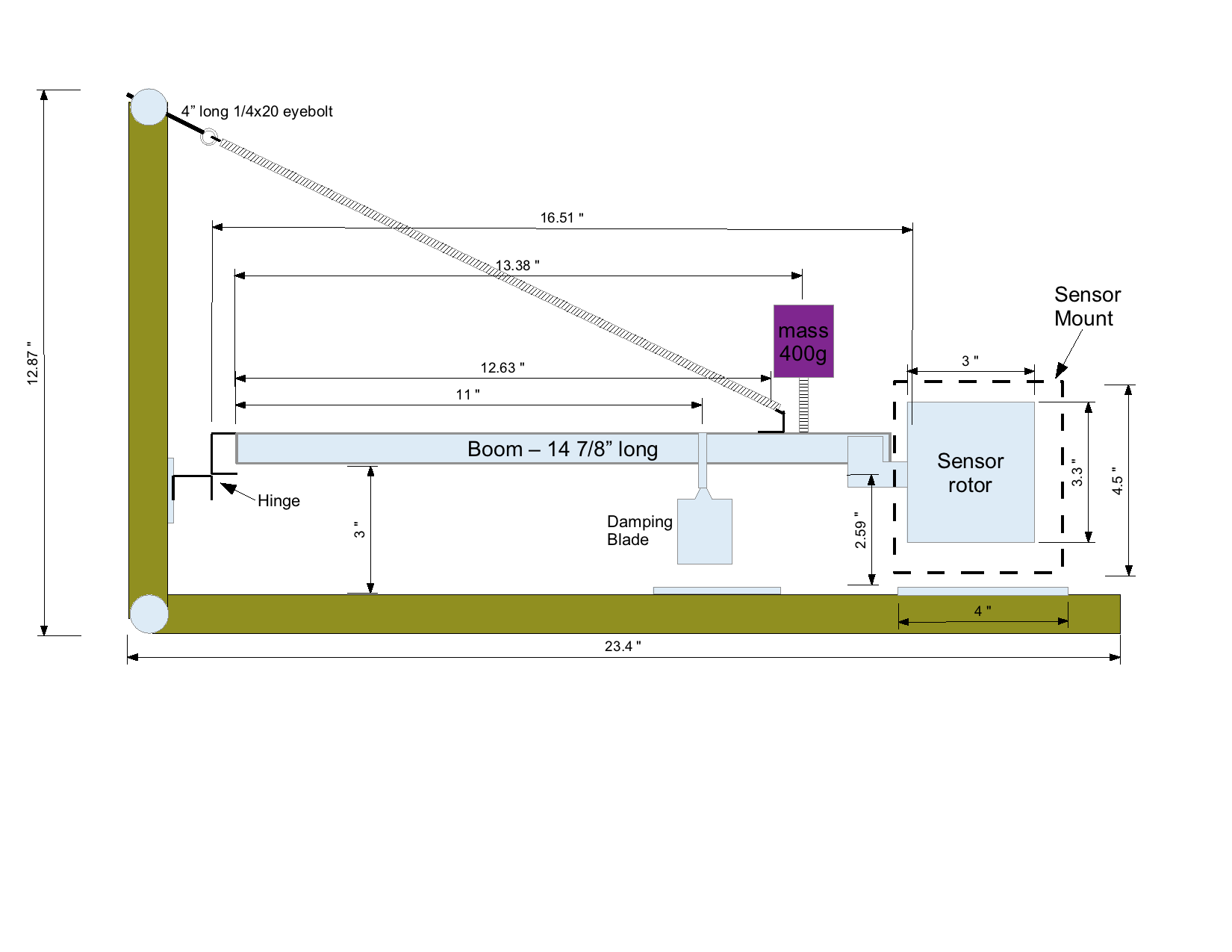
I chose a Lacoste type system, which uses a horizontal pendulum suspended by a spring as shown below (the figure is also from the Havskov paper.) Theoretically this setup can have a natural frequency close to zero.

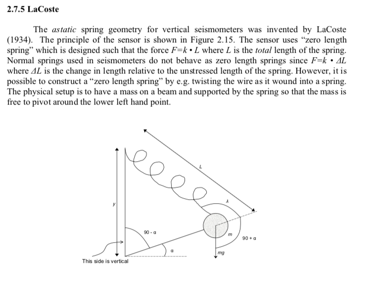
But a "zero length spring" is hard to get. With reasonably small dimensions, 12" high by 24" long, the natural period is around 2 seconds. If I coupled this pendulum with a displacement sensor instead of the usual velocity sensor, then the effective sensitivity would be as good as a 20 second period pendulum. That's the fundamental mechanical approach of this seismometer.

statorMount-Part.stl

3D printable part to replace the wooden piece used to mount the stator at the end of the boom.

Standard Tesselated Geometry - 100.67 kB - 03/02/2023 at 01:32

Download

ArchivePlotter.py

Program for viewing data from archived data on a hard drive (see seedlinkArchiver.py) Requires python and ObsPy installed.

x-python-script - 5.48 kB - 03/09/2019 at 20:41

Download

seedlinkRemote.py

Program for viewing streaming data from a ringserver or seedlink server. Requires python and ObsPy.

x-python-script - 7.74 kB - 03/09/2019 at 20:40

Download

seedlinkArchiver.py

Python program to make daily archives of the seismometer data stream. Requires python and ObsPy. You will need to make changes to the log file location and the stored data location to match your system.

x-python-script - 8.95 kB - 03/09/2019 at 13:50

Download

Seismo.zip

This a directory containing all the files and programs required to run the seismometer on a Raspberry Pi. The path for this directory must be /home/pi/programs/Seismo. There must also be a symbolic link : /home/pi/ringserver/mseed that points to the location of the mseed files used by the ringserver. (e.g. ln -s /media/pi/THUMBDRIVE/mseed /home/pi/ringserver/mseed)

Zip Archive - 177.15 kB - 03/09/2019 at 15:35

Download

View all 12 files

  • Corrosion

    Bud Bennett02/27/2023 at 05:22 1 comment

    It's been a few years since I inspected the inside of the seismometer enclosure. Recently, the seismometer output seemed to be stuck and not responding to large events, and the absolute value of the counts seemed to be too large negative. So eventually I removed the cover of the enclosure and peeked inside. Everything appeared to be corroded!

    I removed all of the diet coke cans inside the enclosure that were used to increase thermal mass -- four of them were less than full. I assume that they leaked somehow and the moisture caused the corrosion. 

    The rotor blade was sticking against the spacers used to separate the two stator blades. 

    Most of the hardware seems unaffected, but the 4-40 bolts holding the stators are completely rusted, along with the two springs. I replaced the 4-40 bolts with brass versions that should perform better under moist circumstances. The springs were replaced after a trip to Lowes. Prices have gone up. When I first purchased the springs they were $3.50 per package of two -- now its $5.00.

    I decided to replace the wooden plug that supported the stator blade with a 3D printed version. It should add more stability (in that it is not as susceptible to moisture) and could be fabricated with better tolerances. A few minutes designing with FreeCAD, coupled with an hour of printing yielded a near-perfect part.

    The slot gives perfect alignment and the two screw holes will hold the stator in place better than the friction fit from the wooden piece. Here's what it looks like installed:

    This is the entire seismometer, with PCB sensors, new springs and some new hardware. I wiped all of the non-stainless hardware with WD-40. It's ready to be re-installed into the enclosure and begin taking measurements again.

  • ObsPy

    Bud Bennett03/09/2019 at 15:52 0 comments

    ObsPy is a collection of seismological programs in Python (2 and 3) that aid in recovering streaming data for analysis, filtering and display of the data. The wiki page is here. ObsPy runs on nearly all modern OS platforms: Windoze, Mac, Linux.  It can be installed on a Raspberry Pi with a simple command:

    sudo apt-get install python3-obspy

    It is much more difficult to get it running on a Mac. Embarrassingly, I have forgotten how I got it running on my Mac desktop machine so I'm no help there (it was either MacPorts or Brew).

    I use ObsPy because I find it flexible and better documented than the other public domain seismology programs available in the wild. The filtering capabilities don't generate wild group delay distortion or strange transient effects like I've seen in other programs. This is important to me since the seismometer streams raw data from the cap2dig converter and it needs some post processing to get rid of temperature and drift artifacts.

    Archiving Data:

    The Raspberry Pi B+ that is attached to the seismometer is not powerful enough to do much more than manage the cap2dig converter and the ringserver. The CPU usage hovers around 40-50%. I tried to have it archive the data from the ringserver on a daily  basis, but it bogged down the machine so badly that the ringserver failed. So now I have a separate Raspberry Pi 2 sitting on the network whose sole job is to archive the daily data stream generated by the seismometer. This is handy since the archival process happens whether or not my desktop machine is running. Every so often I transfer the archived data files to my desktop machine and can view the data anytime after that. It would be tempting to just increase the size of the ringserver buffer, but then the size of the buffer file gets too unwieldy for the ringserver.

    The archiving program is seedlinkArchiver.py and is located in the files section of this project. It is managed as a service under systemd and starts upon boot up. I found that it is better to obtain short, 15 minute long, data snippets from the ringserver to avoid the higher probability of getting server errors with long data segments. The archiver checks the time every 10 minutes. If a new UTC day ends then it collects the previous day's data stream from the ringserver. The stream is collected in 15 minute chunks, which the user can lengthen or shorten. If there are gaps in the stream longer than 1 second, or there is a communication error, the program will try three times to get good data. Each chunk of the stream is then concatenated with the others to obtain the entire day's stream. Believe it or not, this approach is faster than just getting the entire day's stream in one long piece. The day's stream then high-pass and/or low-pass filtered to user adjustable values and then archived to a usb thumb drive in both filtered and raw data formats.

    Viewing the Data:

    There are two basic programs to view the data: directly from the ringserver over the network, or via the archived data streams.

    seedlinkRemote.py is a program to view data over the network. (It is possible to get real-time data using a program called seedlink-plotter.py, but it can't really deal with raw seismometer data that contains a significant DC count offset.) I use seedlinkRemote when I wish to view quake events that have not been archived yet. The program has three options: a dayPlot, hourPlot, or custom plot. A calendar widget allows the user to pick a date and then offers the three choices. If the user chooses a dayPlot, he has the option of filtered/raw data, and the magnitude threshold of the event notation. A typical dayPlot with filtered data, and  >5 magnitude quakes noted, looks like this:

    Pretty boring here in Colorado. We have very stable earth.

    The hourPlot only allows for filtered or raw option (the junk in the middle is probably wind noise):

    Custom plots are good for isolating a single...

    Read more »

  • Up and Running with New Sensor

    Bud Bennett02/23/2019 at 05:36 0 comments

    A few days ago I replaced the homemade displacement sensor with a shiny new set of PCBs for the rotor and stator plates. It's been pretty quiet out there in the world lately, but today there was a rather large event in Ecuador -- magnitude 7.5 near the border with Peru. The quake was captured by the seismometer.

    Unfortunately, there was another spurious event recorded at 18:48UTC. This kind of stuff happens when you disturb the seismometer (or it was an insect crawling around on the boom) -- and it takes a few days for the mechanism to settle out. In any case it appears that the new sensor is working well.

    This event is about 6400km from my place in Colorado. Previously, I estimated that 1 count of the cap2dig converter was equivalent to about 0.3nm of displacement. This quake caused the floor of my garage to move about 3µm.

    Here's a stripline plot of the same event (added text is mine).

    This is what the Z-axis seismometer in Albuquerque, NM picked up:

    I might need to adjust the filter parameters a bit to pick up the lower frequency energy...but this is what the Z-axis seismometer picked up in Pinedale, WY:

    and it's pretty close to what I got.

  • The Software

    Bud Bennett02/18/2019 at 13:18 0 comments

    I will make all of these programs available to download from the files section of this project or link to the webpage for download. I need to do a bit of cleanup and improve the documentation on my stuff first.

    Overview:

    The capacitance to digital converter is not listed among the supported data converters for the popular seismic software packages -- Earthworm, et al. I had to write a custom program to extract the data from the cap2dig converter and massage it into a form that the standard seismic server programs would understand. Here's the flow:

    The cap2dig converter uses I2C to interface to the Raspberry Pi computer. It runs in continuous mode -- sampling at 16.2Hz -- and interrupts the Pi on GPIO4 when each conversion is done. The data is collected by a Python program, seismo2mseed.py. The program creates two arrays: the resultArray for the realtime web server, and the seedArray for the seismic data stream server.

    When the seedArray reaches 512 samples it is packed into an ascii file and fed to a program called ascii2mseed, which creates another file containing the miniseed data packet.

    Lastly, a daemon program called ringserver watches the directory containing the miniseed files and adds the data packets to the data stream that it serves on port 18000. At this point the data stream is available to any computer running standard seismic software -- Earthworm, Quake, ObsPy, etc. 

    I use ObsPy running on a desktop iMac to view the data in several formats. ObsPy is a collection of Python programs specific to seismic data manipulation.

    seismo2mseed.py:

    The heart of this program is a function called getData(). It is called when the cap2dig converter signals that a sample is ready by a falling edge on GPIO4. There is also a Class called AD7745 which contains all of the methods to configure and extract data from the cap2dig converter. The AD7745 requires sequential reads of the I2C port that the standard python smbus libraries don't support very well, so I'm using the Quick2Wire libraries instead. The Quick2Wire stuff is very old, but still works fine in Python3.

    A timestamp is added to the data and it is appended to both the resultArray and the seedArray.

    When the length of the seedArray is 512 samples the data is packed into a simple text file with this format (explained in the next section), and ascii2mseed is called in the background:

    TIMESERIES EI_AEGI__BHZ, 512 samples, 16.2 sps, 2019-02-18T13:47:12.273422, SLIST, INTEGER, Counts
      -1272258    -1272447    -1272290    -1272276    -1272222    -1272194  
      -1272313    -1272208    -1272297    -1272342    -1272303    -1272273  
      -1272373    -1272268    -1272423    -1272324    -1272484    -1272189 

    The samples are integers representing the the conversion Counts of the cap2dig converter. The integers range from -2^23 to +2^23, or ±8,388,608.

     I added a webserver to allow the raw or filtered data to be viewed real-time. I was familiar with Bottle to create and manage a webpage so that is what is used. Bottle can be obtained here.

    This is a screenshot of the webpage:

    I'm using Flot to plot the data. The data sent to the webpage is decimated 8:1 to reduce loading times. Every 10 seconds or so the data is updated and scrolls. Usually, there is about 1 hour of data to view.

    ascii2mseed:

    This program is available from IRIS. Simply download it and install on the Raspberry Pi using make. The ascii data file must include a header with the following information:

    "TIMESERIES SourceName, # samples, # sps, Time, Format, Type, Units, Headers"

    followed by the data in tabbed format. It is pretty well documented in the GitHub repository.

    The miniseed file is uniquely named with a timestamp and deposited into a directory on external thumb drive attached to the Raspberry Pi.

    ringserver:

    This program runs as a daemon under systemd. It performs a seedlink...

    Read more »

  • Damping Calibration

    Bud Bennett01/27/2019 at 16:17 0 comments

    At this point, you need to have the seismometer enclosed and the software and hardware working to produce a measurement of displacement. The undamped pendulum should have a natural period of about 2 seconds. This means that if you perturb the pendulum slightly it should "ring" for a long period of time, like this:

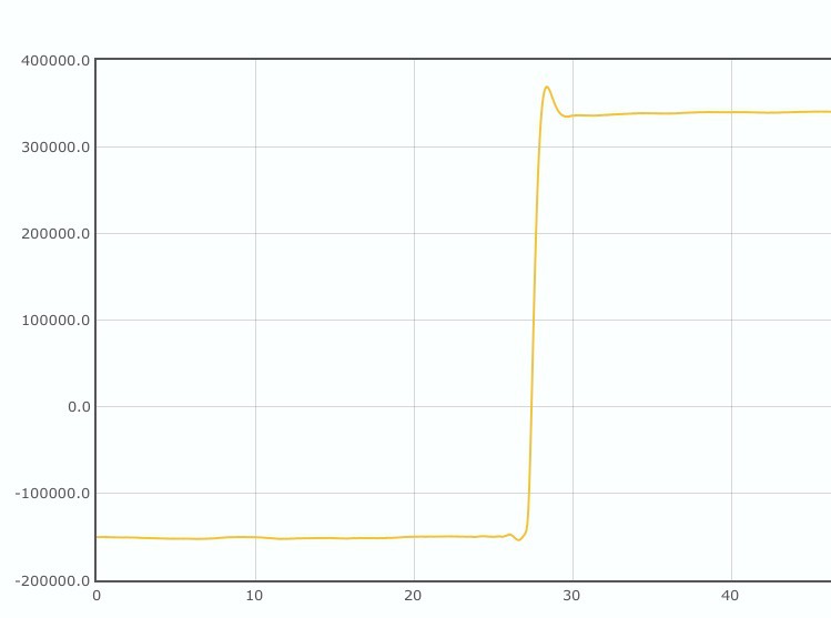
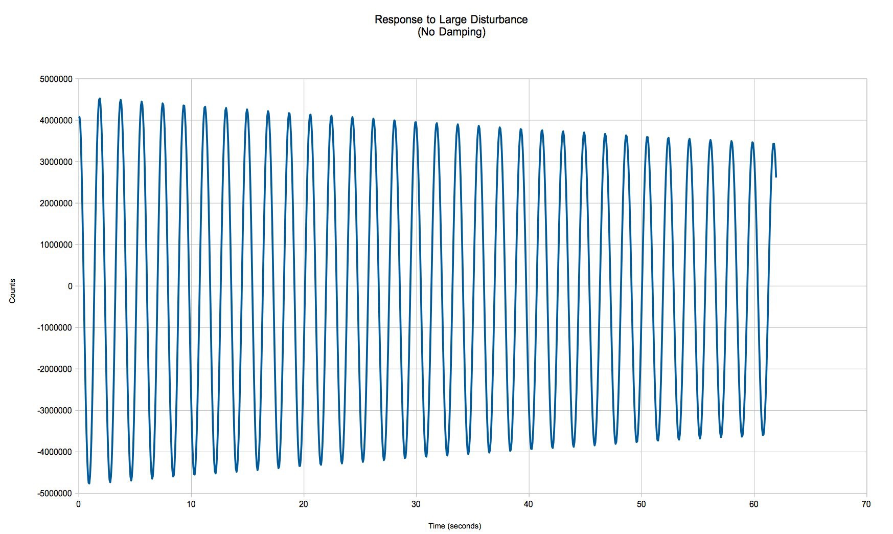
    From the above plot, the natural period of my seismometer is 1.875 seconds. The amount of decay over the 60 second measurement is indicative of frictional forces at work.

    I referred to my favorite reference article at this point to calibrate the magnetic damping:

    Here's what my test weight looked like when I weighed it:

    The thread runs under the peak of the "V" of the paper weight. The feet help to keep it stable for positioning on the boom. 

    Since this is displacement sensor the response when the weight is lifted from the boom will be a step up in counts -- not a pulse like you would get with a velocity sensor, as per the article. What you are aiming for it something called "critically damped". When you achieve critical damping the frequency response is not peaked and you get a fast settling time from a disturbance. This is the final calibrated response of my seismometer:

    What's amazing is the amount of displacement from such a small difference in mass -- nearly 500,000 counts! Note the small overshoot of the response when the weight is removed. I believe it is about 8% of the step height, which yields the same 12:1 overshoot ratio as the reference article. You change the response by moving the magnet frame to cover more or less of the damping blade until you run out of time or patience (just kidding.) But it is a slow process that you only have to perform once. 

    After I was satisfied with the response I dribbled some epoxy against the base of the magnet frame (without moving it) to hold it in place.

  • Seismometer Electronics

    Bud Bennett01/26/2019 at 05:03 0 comments

    The electronics are the easiest part of this endeavor, thanks to Analog Devices, Inc. The AD7745 IC is a 24-bit fully differential capacitance to digital converter. It is highly integrated, so very few external components are required. Here is the entire circuit schematic.

    My original design used a LD2981 3.3V LDO instead of the XC6206. I decided to save a few pennies with the XC6206 since the current loading of the AD7745 is less than 1mA. Total cost of the electronics is about $12.25 -- the majority of which is the AD7745 ($11.28). The circuit board connects to the pin header of the Raspberry Pi, but hangs outside the Raspberry Pi to avoid potential interference problems.

  • Sensor Design

    Bud Bennett01/26/2019 at 00:00 1 comment


    Please forgive me. It's been nearly 4 years since I worked on this problem. A lot of the details have probably been forgotten in the interval. There is a lot of ground to cover, so this might be a very long log entry.

    Initially I thought that the way forward was to use a velocity sensor. But subsequent investigation led me to conclude that a displacement sensor was best. I somehow stumbled upon an article by Dr. Randall D. Peters, a professor of Seismology at Mercer University at the time. I lost the original article, but Dr. Peters has written extensively on the subject of using capacitive displacement sensors to detect movement of seismometers, and even patented (U.S. Patent # 5,461,319, Oct. 24, 1995) the concept of a differential capacitance transducer. I will make the patent available in the files section of this project.

    The Concept:

    Dr. Peter's basic approach was to create a capacitive displacement sensor that was inherently non-contact (therefore no friction), highly linear, differential, and very sensitive. This is a figure from a Dr. Peters paper describing the sensor.

    The sensor consist of three plates, which are superimposed on one another: the exciter plate (at the left), the rotor plate (middle) which moves, and the capacitor plate (right). The figure above refers to "linear motion" to simplify the concept. In our case the motion is rotational -- an easy translation.

    So what you have here is an exciter plate where the stimulus is applied, a rotor plate that "blocks" the excitation, and a capacitor (static) plate that measures the result via differential means (an amplifier, in this case.) Displacement is measured when the rotor plate moves - it changes the capacitance measured between the excitation (a stator plate) and the capacitance (a stator plate) when the rotor plate changes position. 

    The rotor plate blocks the signal from the exciter plate to the capacitor plate wherever there is metal. If the rotor is positioned so that it exposes the exciter plates evenly, then the effective capacitance of the sensor is zero. If the rotor plate moves up or down even the slightest amount then the exposed plates of the exciter are unbalanced and the capacitance changes in direct proportion to the movement. Note that the exciter electrode set consists of cross-coupled plates. This arrangement provides for zero displacement when the stator is aligned with the stators, but when the rotor moves it makes the capacitance change (positive or negative) in direct proportion to the displacement.

    The Implementation:

    Unfortunately, the boom is fixed at one end so the displacement is rotational in nature. Fortunately, Dr. Peters provided some answers. He was selling a seismometer that employed two pendulums, x and y, called the Volksmeter, for about $1500. The users manual for the Volksmeter contained a lot of information.

    He is giving it all away at this point. I was able to design the two stator plates and the rotor plates from all of the information that he had given away. The patent was granted in 1995. Normal patent life is 20 years, so it has expired as of this writing. Note the disclosure of the AD7745 chip.

    My Design:

    The AD7745 is a differential 24-bit capacitance-to-digital converter. It has a maximum differential capacitance capability of about 4pF. It is desired to create a capacitor that will generate nearly ± 4pF for a full scale movement. 

    So what is a full scale movement? I arbitrarily chose this to be ±5mm. We don't get a lot of seismic activity here in Colorado. There is no need to be able to respond to large displacements. A ±5mm ranges is huge compared to expected incidents. The 5mm range also must include drifting of the mechanical system over time and environmental conditions (temperature, humidity, etc.) The 5mm range sets the...

    Read more »

  • Mechanical Details

    Bud Bennett01/23/2019 at 05:55 0 comments

    This log contains the details of the mechanical stuff -- the dimensions and materials. I will attempt to generate a concise description of how to build the seismometer in the Instructions section. I believe these drawings are accurate. Sorry for the Imperial dimensions, but that's the standard here in the U.S.A.

    A large part of the design is simply copied from this article. I highly recommend that you read that article prior building this unit since a lot of it is similar and the detail about assembling the damping unit is identical and explained well . I started out using wooden frame components to keep the cost low while testing out the concepts. I migrated to copper tubing (plumbing pipe and accessories) because I was concerned that the stresses in the wood screws was causing artifacts in the sensor data -- this was probably unfounded. In any case, once you get the frame soldered together there isn't anything that affects it other than temperature.

    The critical dimension is the distance from the hinge to the sensor -- this must be 16.5" due to the design of the sensor. It is also desirable to keep the length of the spring close to what is shown here, but spring tension can be adjusted easily by changing the mass and the eyebolt. The placement of the mass should be very close to the point where the spring is attached to the boom to lessen the force on the hinge. Almost everything else can be adjusted during assembly.

    Note: I may be changing this log as I document other parts of the project. I'll remove this note when things become more stable.

    Above: the side elevation. Below: the front elevation.

    Seismometer Mechanical Bill Of Materials:

    boom - 4ft x 3/4” aluminum trim channel —(Lowes #215871) $10.49

    Springs(2) - Lowes #199346 x 1 - $3.50

    24” steel framer's square - Lowes #118056 - $5.97

    Frame:

    1 - 22” long 3/4” copper pipe, for the base

    2 - 11” long 3/4” copper pipe

    1 - 4.125” long 3/4” copper pipe

    2 - 3/4” copper 90° elbow

    3 - 3/4” copper tee

    2 - 1.5” long 3/4” copper pipe to connect tees

    2 - 3/4" long 3/4" copper pipe to reinforce tees at ends

    11 gauge(?) steel sheet to connect hinge to boom.

    4 - 1/8” thick aluminum plates to attach boom, damping, and sensor.

    8” x 24” glass plate to rest unit on floor.

    Feet:

    3 - 2.5" 1/4x20 machine screw

    6 - 1/4x20 nut

    3 - 1/4 flat washer

    Hinge:

    2 - 4" long aluminum trim channel

    1 - 1/8" aluminum plate

    4 - 1.25" #8/32 machine screws

    4 - #8 split washer

    4 - #8/32 nut

    blister pack

    +++

    Boom:

    1 - 14 7/8" long aluminum trim channel

    1 - 7/8" long aluminum trim channel (for spring attachment)

    3"x4" 22gauge sheet steel

    1.25"x1.25"x3/4" wood block

    2 - 1/2" #8 sheet metal screw

    1 - 1" #6/32 machine screw

    2 - #6 flat washer

    1 - #6/32 nut

    4 - 3/8" #10/32 machine screw

    4 - #10/32 nut

    1 - 1/2" #10/32 machine screw

    1 - #10 split washer

    1 - #10/32 nut

    Mass:

    1 - empty can of tomato paste

    1 - 1.5" 1/4x20 machine screw

    3 - 1/4"x20 nut

    1 - 1/4" split washer

    ~400g lead weight

    Sensor:

    4 - #4/40 x 1.5" screw

    8 - #4 flat washer

    12 - #4/40 nut

    4 - 3.5mm spacers

    6 - 0.5" #10/32 machine screw

    6 - #10 split washer

    6 - #10/32 nut

    6 - #10 flat washer

    2 - 3/4" copper pipe hanger

    1 - 4" long aluminum trim channel

    4"x4.5"x1/8" aluminum plate

    2.5x4"x1/8" aluminum plate

    Damping:

    3 ea. 1.5” x 1/4x20 bolts - round head

    9 ea. 1/4x20 nuts

    4 ea. Neodymium Magnets

    6 ea. 2"x2.75"x1/16" steel plate...

    Read more »

View all 8 project logs

  • 1
    Building the Frame
    1. Cutoff two pieces of copper pipe 11" long, one 22", one 4 1/8", and two 1.5". Use a pipe cutter for this, it will make nice square edges.
    2. Drill a 1/4" hole through the center of the 4 1/8" piece for the eyebolt. 
    3. Insert the 1.5" long pipe as connectors between the three tees. They should allow the tees to butt up against each other with no gaps. Insert the 11" pipes into the outer tees and attach the elbows to the other end with the 4" pipe. The 11" pieces should be parallel to each other -- if not, then you might have to shorten the length of the 4" pipe or make a brace help with alignment later.
    4. You can drill the 1/4" holes for the legs now, or wait until everything is soldered up, depending upon what drill type you have. I drilled the two leg holes in the outer tees at this point since it was easier to do that with a drill press before the frame was assembled. Try to get the hole aligned with the tee, but it's not that critical if you're off a degree or two.
    5. Time to solder the frame together. You will need a propane torch, plumbing solder, acid flux paste, and a cheap brush to apply the flux. The disposable flux brush is usually sold next to the flux paste. Apply a generous coat of flux paste to both the outside end of the pipe and the inside of the elbow or tee. You can either clamp it all together and solder it, or do it piece-by-piece, but make sure that the base is at right angles to the back support and that the two back pieces are parallel to each other. Also, line up the hole you drilled in the 4" piece with the proper angle for the spring -- it is not critical, but make a good effort here. You solder each joint by heating up the joint with the torch while pressing the end of a length of solder against the joint seam until the solder melts a flows into the joint. Make sure that the entire joint is filled with solder. I'm sure there are plenty of YouTube videos to explain the procedure. Keep wet rags over the nearby joints to prevent them from loosening as you apply heat.
    6. Let the frame cool, then clean it thoroughly to remove any residual acid flux paste.
    7. If you didn't drill 1/4" holes for the legs previously, then do it now. At this point I soldered 1/4x20 nuts to the bottom of the frame for each leg bolt, but you could glue them on if preferred. If you want to solder the leg nuts then use a bolt to hold the nut to the frame and cover the bolt and other parts of the frame with a wet rag to keep them cool. Apply flux paste to where the nut and pipe join or the solder will not flow properly. Don't get flux on the bolt. Clean clean it off afterward.

    Here's detail photos of the legs. The legs aren't perfectly aligned, but it's not critical.

    I placed a short piece of pipe inside the tee to reinforce it since the tee is pretty thin. Also all of the legs have been ground to a dull point.

  • 2
    Attach the Eyebolt
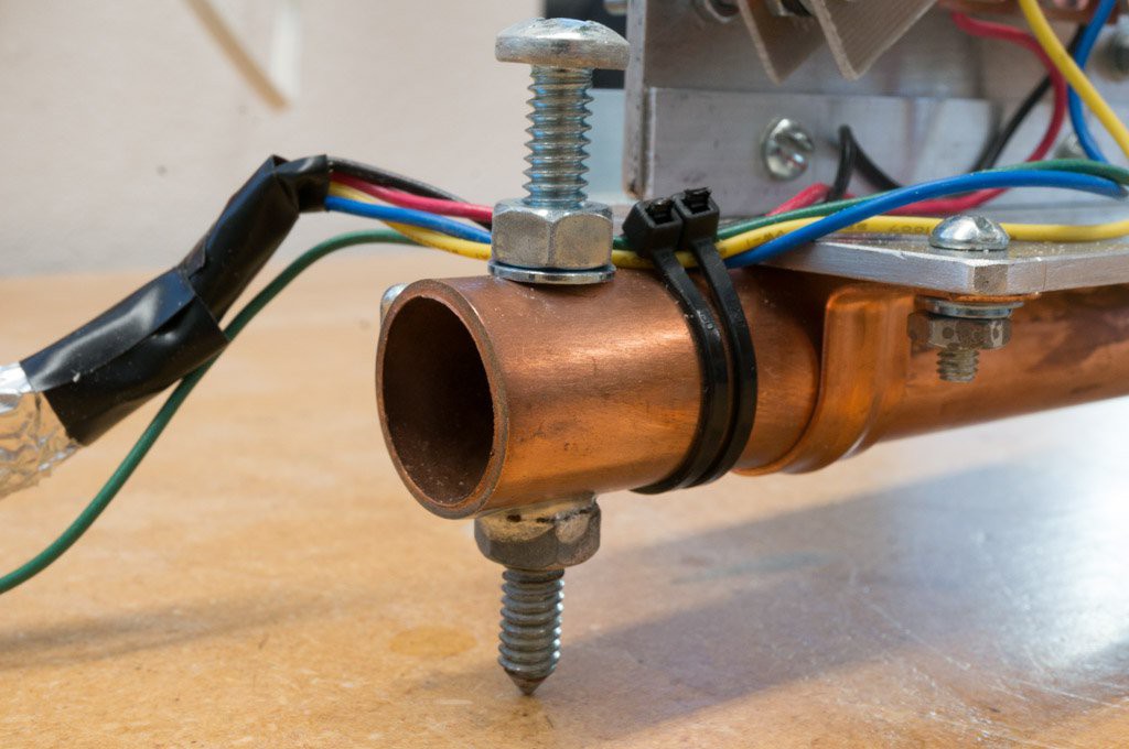
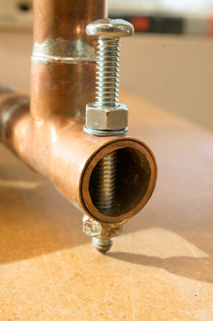
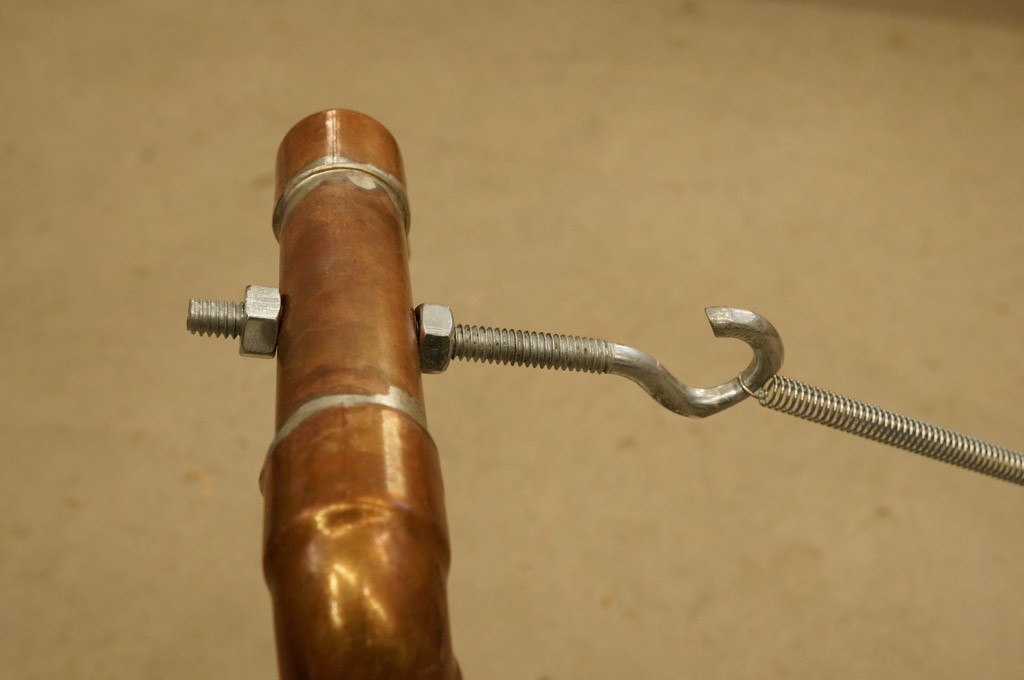
    Cut the last bit of the eye to form a hook instead. The spring has a small loop at the end so you may have to grind the point of attachment at the hook to fit. I also filed a groove on the inside of the hook for the spring to sit so that it would not move and create unwanted artifacts. It is desired to have the spring only touching that groove. You can do all of this later, when the position of the spring will be more easily determined.
  • 3
    Make the Hinge

    It is easier to show a photo of the hinge than to describe it. Here’s a view of the entire hinge.

    The hinging material is actually 4 straps of plastic made from blister pack — that tough plastic used to encase stuff for sale like SD cards or small hardware pieces. The straps are mounted on two 4” pieces of aluminum channel — the upper channel has its channel facing forward, while the lower channel is facing downward. Two of the straps, the outer straps, are set horizontally, while the inner straps are vertical. Together the straps allow the joint to flex up or down easily while preventing side-to-side movement. Here’s two more details of the hinge arrangement.

    The plates that are used to connect the hinge to the boom and the hinge to the frame should be made first. 

    The plate that connects the hinge to the frame is a 6" x 2 1/8" piece of 1/8" aluminum. Drill two holes 3/4” from the bottom spaced 2” from each end of the long side. Don't drill the holes to mount it to the frame yet.

    Use this drawing for the hinge-boom plate. 

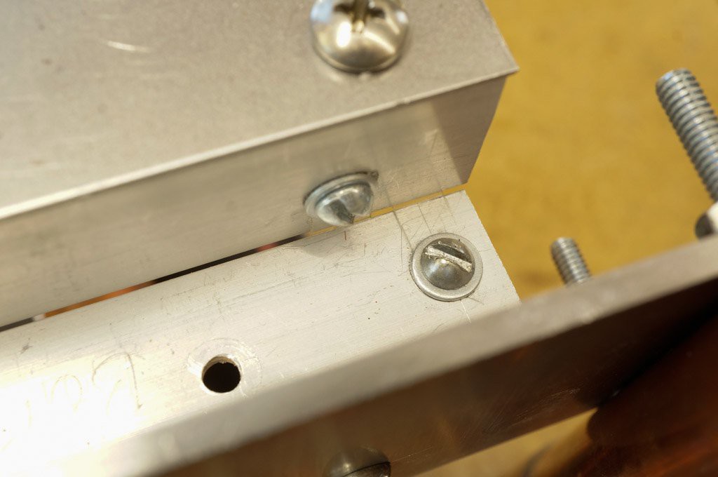
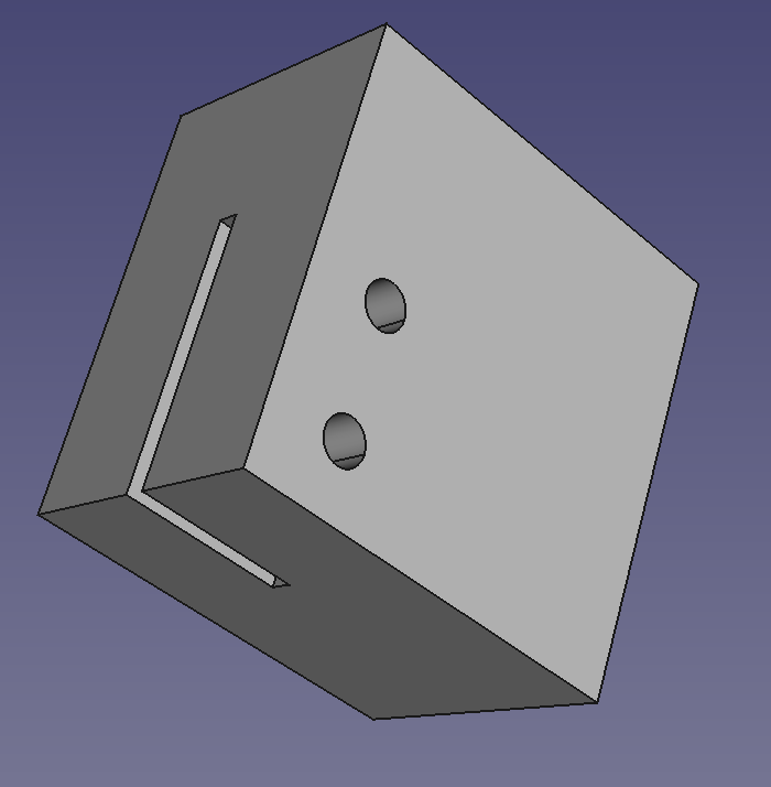
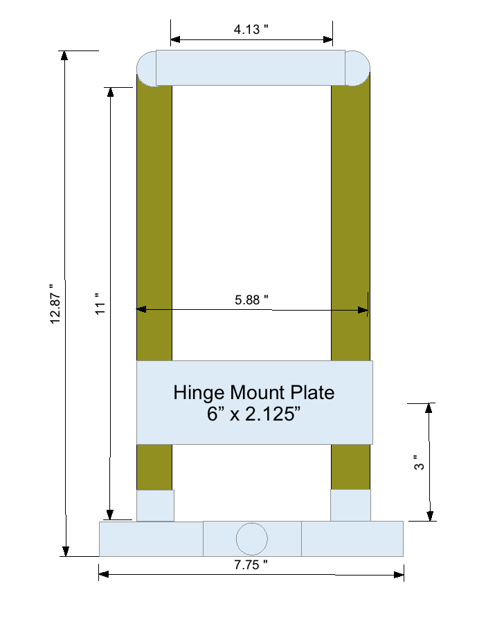
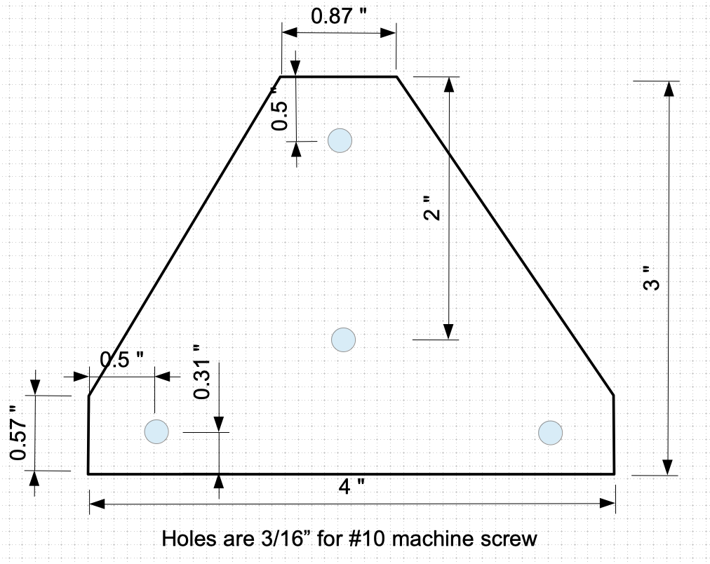
    My drawing software can't make fractional dimensions. The 0.87" translates to 7/8", 0.57" is 9/16" and 0.31" is 5/16".
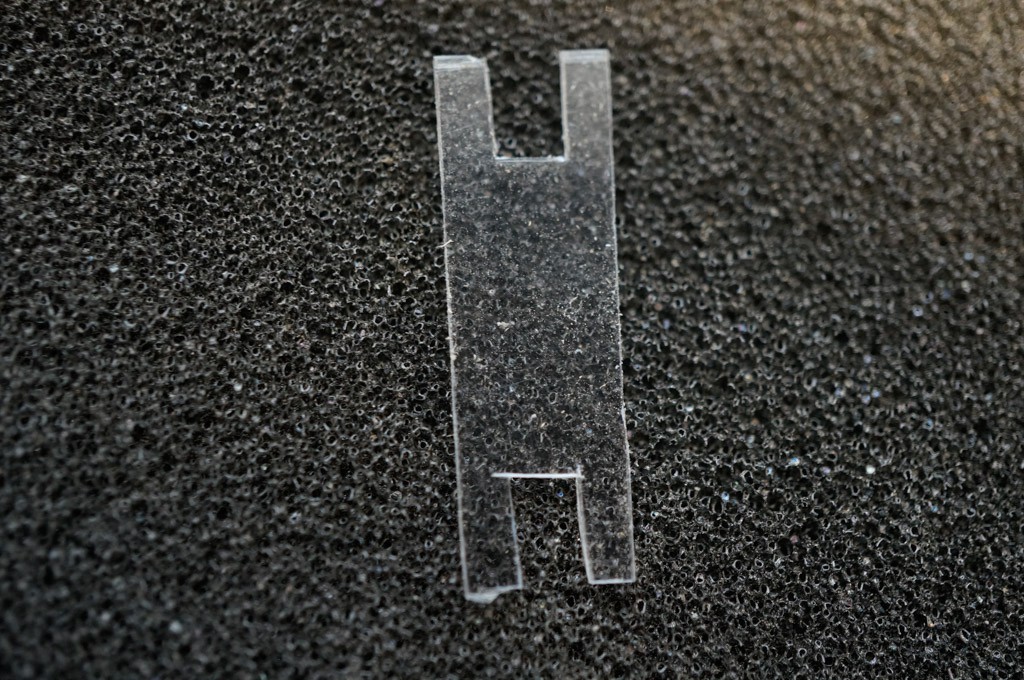
    1. Cut the hinge-boom plate from the 22gauge flat steel plate and drill 3/16” holes for #10 machine screws at the marked locations.
    2. Cut 2 pieces of aluminum channel 4 inches long.
    3. Align the hinge-boom plate with the piece that will become the top hinge channel and drill two holes in the channel using the holes drilled at the back of the hinge-boom plate as a guide.
    4. Align the channel piece that will become the bottom hinge channel to be centered over the two holes drilled in the hinge-frame plate -- take pains to keep the bottom of the channel and the hinge-frame plate parallel. Drill two holes into the channel piece using the holes in the hinge-frame plate as a guide. You can do this operation later, but this way you don't have to worry about damaging the hinge.
    5. Align the 2 channels and mark lines across both channels where the centers of the hinges should be placed — the outer hinges are approximately 1/4” from the channel ends, and the inner hinges are 5/8” in from the channel ends. Drill holes on the marked lines 5/16” from the channel edges facing toward the hinge point. The holes should be sized for the 3/8” #6/32 machine screws that will hold the straps in place.
    6. Make 4 hinge straps from blister pack material. These should be approximately 5/16” x 7/8” with slots cut in each end like the photo below.

      Attach the 4 straps to the channel pieces with 3/8" #6/32 machine screws. Use flat washers between the head and the hinge strap. Use a split washer under the nut. Try to keep the space between the two channel pieces as small as possible since this will reduce the side-to-side movement of the hinge. See the hinge detail photos above. 

      Set the hinge assembly aside for later.

View all 13 instructions

Enjoy this project?

Share

Discussions

Bharbour wrote 01/25/2019 at 23:41 point

Nice writeup, thanks!

  Are you sure? yes | no

Dan Maloney wrote 01/21/2019 at 16:48 point

This looks fantastic! I'd love to see more detail about the sensor and the electronics end of this.

  Are you sure? yes | no

Bud Bennett wrote 01/21/2019 at 23:12 point

I'll get to it. I started the project in 2015. Typically, I did not document everything. I decided to create this project when I found a cheap PCB source to make the sensor stator and rotor parts -- using OSH Park was gonna cost a small fortune for the large PCB area required. I'm finding that I have forgotten (and did not document) a lot of information related to the design of the seismometer. I will have to shutdown the seismometer operation in order to get the information needed to allow others to recreated it. 

The electronics are pretty easy, and I have all of the docs for that. But first things first -- the mechanical stuff.

  Are you sure? yes | no

Sophi Kravitz wrote 01/21/2019 at 16:19 point

Hi, what seismic software are you using for data collection?

  Are you sure? yes | no

Bud Bennett wrote 01/21/2019 at 23:00 point

I'm using a custom python script to extract the data from the Cap2Dig converter. Then I call a couple of off-the-shelf programs: ascii2mseed to create an mseed file, and ringserver to make the data available to any seismic display program. I have another Raspberry Pi that just sits in a corner and archives the daily seismic data. I use ObsPy to view the archived data. I'm just beginning to document all of this -- the software stuff is toward the end of the project -- I'll get to it eventually. 

  Are you sure? yes | no

Similar Projects

Does this project spark your interest?

Become a member to follow this project and never miss any updates