 Bud Bennett
This log contains the details of the mechanical stuff -- the dimensions and materials. I will attempt to generate a concise description of how to build the seismometer in the Instructions section. I believe these drawings are accurate. Sorry for the Imperial dimensions, but that's the standard here in the U.S.A.
A large part of the design is simply copied from this article. I highly recommend that you read that article prior building this unit since a lot of it is similar and the detail about assembling the damping unit is identical and explained well . I started out using wooden frame components to keep the cost low while testing out the concepts. I migrated to copper tubing (plumbing pipe and accessories) because I was concerned that the stresses in the wood screws was causing artifacts in the sensor data -- this was probably unfounded. In any case, once you get the frame soldered together there isn't anything that affects it other than temperature.
The critical dimension is the distance from the hinge to the sensor -- this must be 16.5" due to the design of the sensor. It is also desirable to keep the length of the spring close to what is shown here, but spring tension can be adjusted easily by changing the mass and the eyebolt. The placement of the mass should be very close to the point where the spring is attached to the boom to lessen the force on the hinge. Almost everything else can be adjusted during assembly.
Note: I may be changing this log as I document other parts of the project. I'll remove this note when things become more stable.
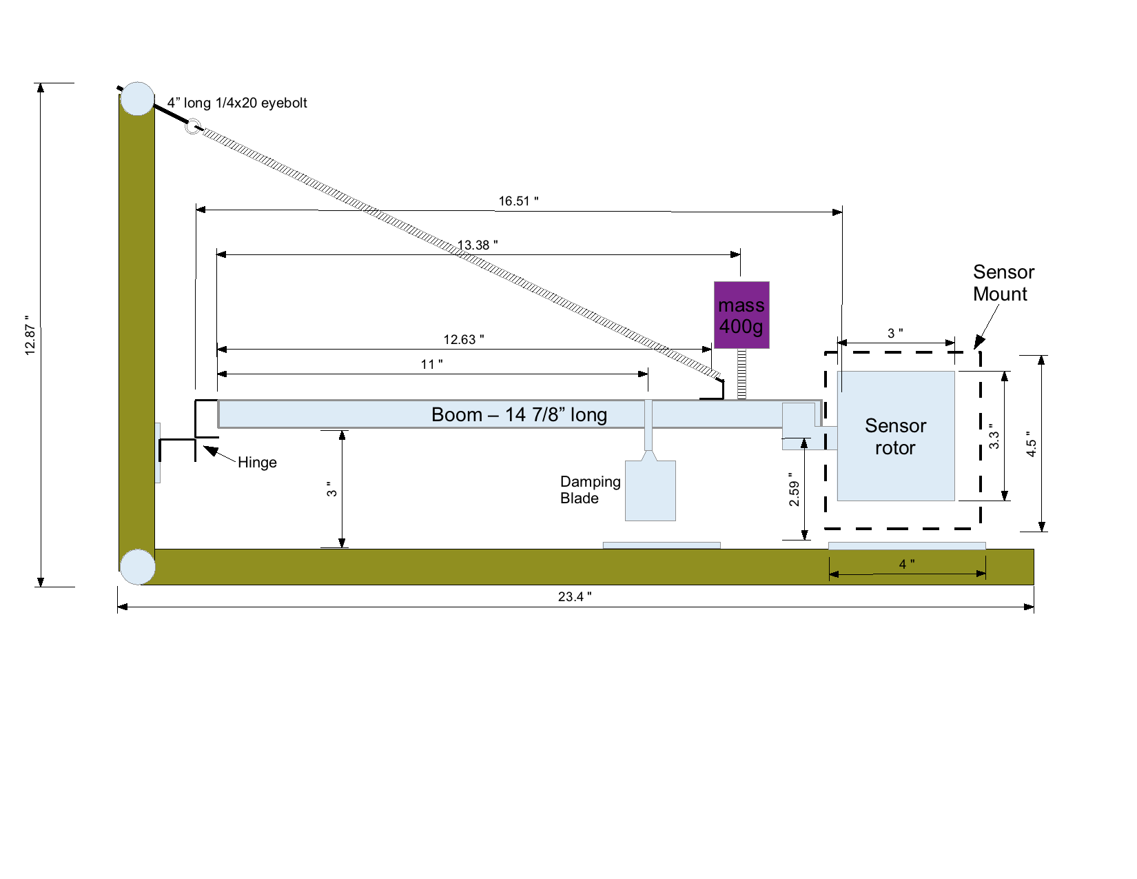
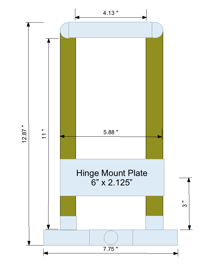
Above: the side elevation. Below: the front elevation.
Seismometer Mechanical Bill Of Materials:
boom - 4ft x 3/4” aluminum trim channel —(Lowes #215871) $10.49
Springs(2) - Lowes #199346 x 1 - $3.50
24” steel framer's square - Lowes #118056 - $5.97
Frame:
1 - 22” long 3/4” copper pipe, for the base
2 - 11” long 3/4” copper pipe
1 - 4.125” long 3/4” copper pipe
2 - 3/4” copper 90° elbow
3 - 3/4” copper tee
2 - 1.5” long 3/4” copper pipe to connect tees
2 - 3/4" long 3/4" copper pipe to reinforce tees at ends
11 gauge(?) steel sheet to connect hinge to boom.
4 - 1/8” thick aluminum plates to attach boom, damping, and sensor.
8” x 24” glass plate to rest unit on floor.
Feet:
3 - 2.5" 1/4x20 machine screw
6 - 1/4x20 nut
3 - 1/4 flat washer
Hinge:
2 - 4" long aluminum trim channel
1 - 1/8" aluminum plate
4 - 1.25" #8/32 machine screws
4 - #8 split washer
4 - #8/32 nut
blister pack
+++
Boom:
1 - 14 7/8" long aluminum trim channel
1 - 7/8" long aluminum trim channel (for spring attachment)
3"x4" 22gauge sheet steel
1.25"x1.25"x3/4" wood block
2 - 1/2" #8 sheet metal screw
1 - 1" #6/32 machine screw
2 - #6 flat washer
1 - #6/32 nut
4 - 3/8" #10/32 machine screw
4 - #10/32 nut
1 - 1/2" #10/32 machine screw
1 - #10 split washer
1 - #10/32 nut
Mass:
1 - empty can of tomato paste
1 - 1.5" 1/4x20 machine screw
3 - 1/4"x20 nut
1 - 1/4" split washer
~400g lead weight
Sensor:
4 - #4/40 x 1.5" screw
8 - #4 flat washer
12 - #4/40 nut
4 - 3.5mm spacers
6 - 0.5" #10/32 machine screw
6 - #10 split washer
6 - #10/32 nut
6 - #10 flat washer
2 - 3/4" copper pipe hanger
1 - 4" long aluminum trim channel
4"x4.5"x1/8" aluminum plate
2.5x4"x1/8" aluminum plate
Damping:
3 ea. 1.5” x 1/4x20 bolts - round head
9 ea. 1/4x20 nuts
4 ea. Neodymium Magnets
6 ea. 2"x2.75"x1/16" steel plate (use framer's square)
1 ea. 1.5” x 1/4x20 brass bolt
2 ea. 1/4x20 brass nut
1.25"x2" 22-24 gauge copper sheet
4 ea. 1/2" #10/32 machine screw
4 ea. #10/32 nut
4 ea. #10 flat washer
4 ea. #10 split washer
2 ea. 3/4" copper pipe hangers
Misc hardware:
1 - 4” long 1/4” eyebolt to attach top of spring.
2 - 1/4"x20 nuts for eyebolt
Discussions
Become a Hackaday.io Member
Create an account to leave a comment. Already have an account? Log In.