 Koen van Vliet
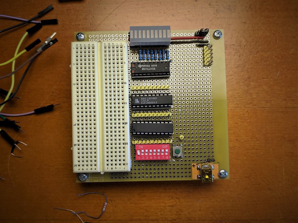
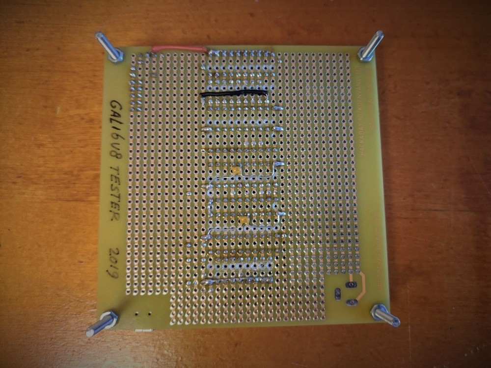
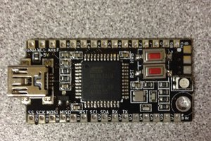
I often find myself needing a combination of SMD and trough hole parts for a project. If I want to make a quick prototype I would like them to be on the same prototype board. Therefore I am developing the prototype board of my dreams starting with basic stripboard with some power connectors and eventually moving up to a combined SMD/trough hole prototype board with various connector footprints.
0%
0%
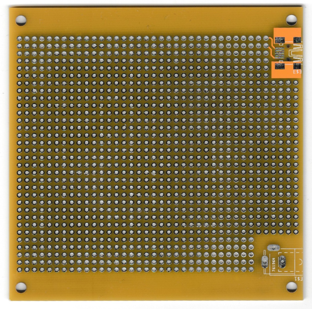
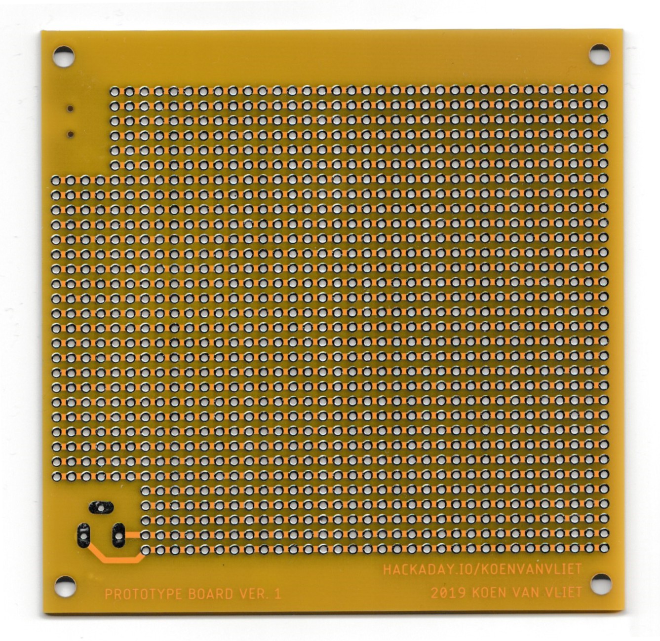
Getting my own perfboard manufactured
Prototype PCBs for conventional and SMD components
Become a Hackaday.io member
Already have an account? Log in.
Just one more thing
To make the experience fit your profile, pick a username and tell us what interests you.
Pick an awesome username
hackaday.io/
Your profile's URL: hackaday.io/username. Max 25 alphanumeric characters.
Pick a few interests
Projects that share your interests
People that share your interests
 The Big One
 technolomaniac
 danjovic
 Frank Buss