Close
0%
0%

LoRaNicator

A wireless telecommunications device, based on LoRa technology, that receives and displays alphanumeric messages.

Public Chat
Similar projects worth following
LoRaNicator is a pager device based on LoRa technology.
- 128x64px monochrome LCD with build in ST7565R-G Controller
- ATSAMD21G18A-AU Cortex-M0+ 32bit low power ARM MCU (Arduino compatible)
- Extremely Accurate I2C RTC
- On-Board Single-Cell Li-Polymer Charge Management Controller
- Smart push-button on/off controller
- Micro SD-Card Slot
- RFM95W LoRa Transceiver (868MHz or 915MHz)
- 3-way Navigation Switch
- High-Efficient Buck-Boost Voltage Converter
- On-Board Coin Pager Motor
- On-Board Piezoelectric Sounder
- GPIO Header for External Periphery
- 2-Layer PCB
- Dimensions LxWxH (mm): 100x78x14 (without battery incl. SMA 8mm connector)
- Open Source Hardware

Project Write-Up

Tiny note: maybe my English sucks a bit, but I hope you can understand the most of the text below :-)

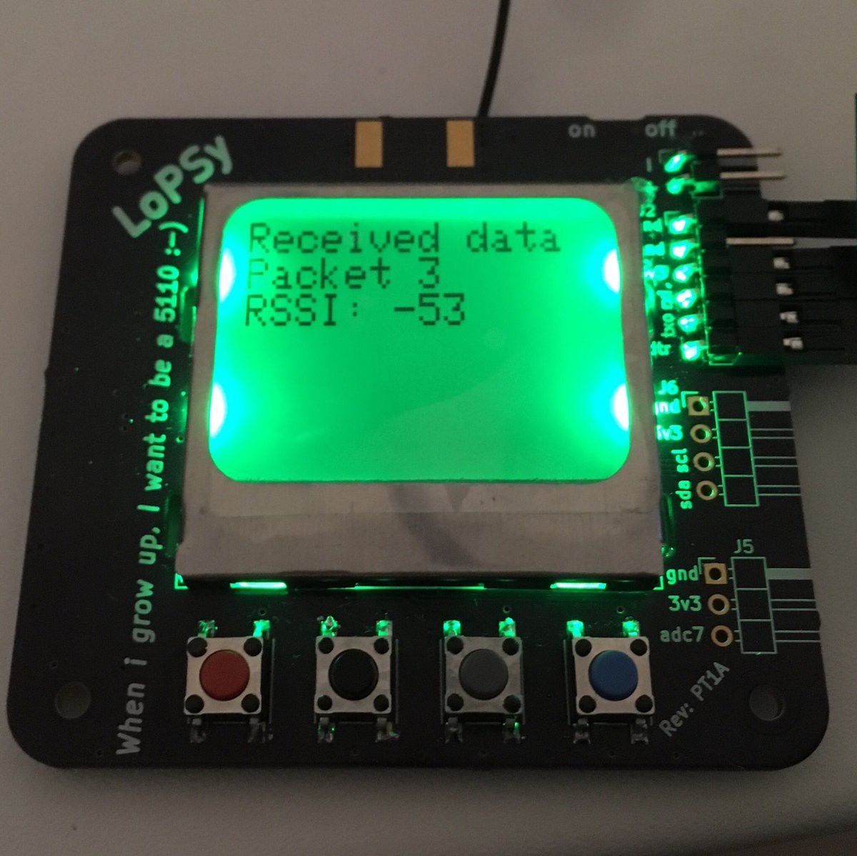
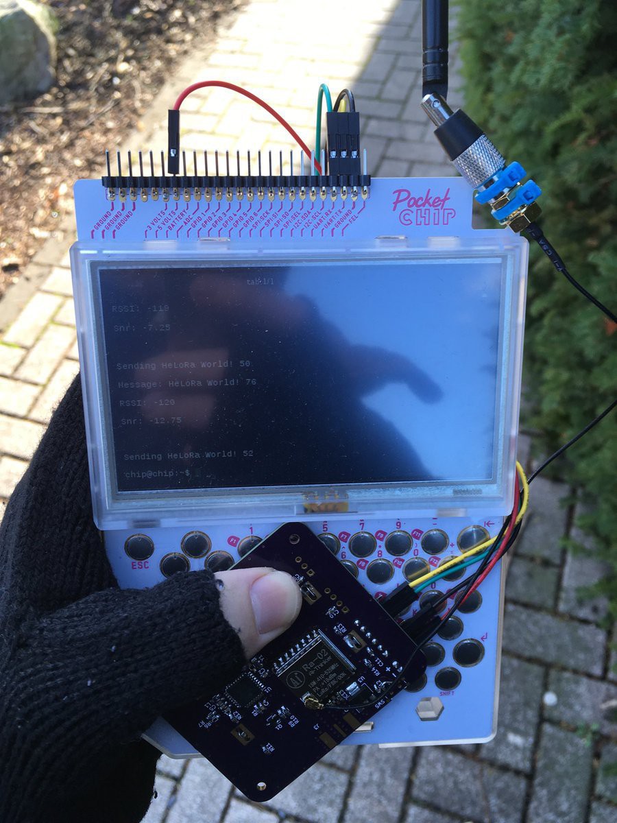
A couple of months ago, I wanted to experiment with LoRa modules. I started with a breadboard, two AI-Thinker Ra-02 LoRa modules, Nokia displays and ATmega328 boards. After a couple of experiments, I designed a tiny board, my first LoRa pager.

I played around with the new board for a while, made some range tests and got some ideas for improvements.

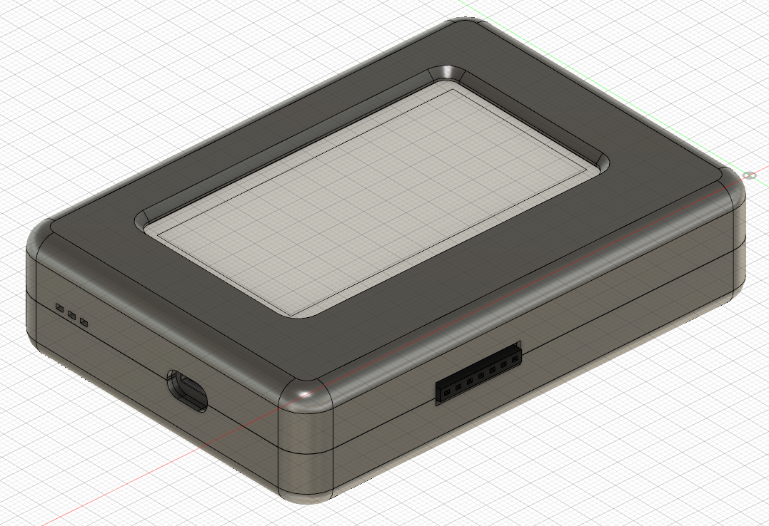
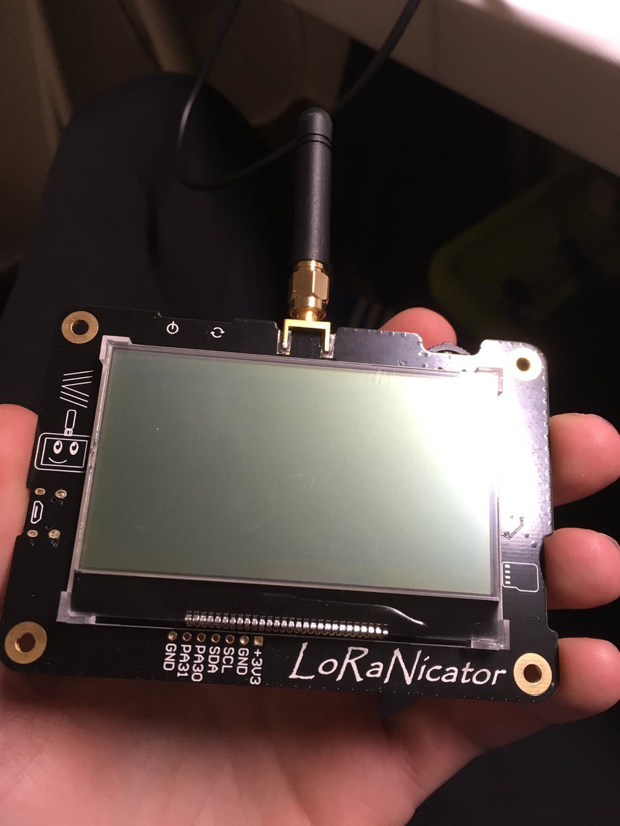
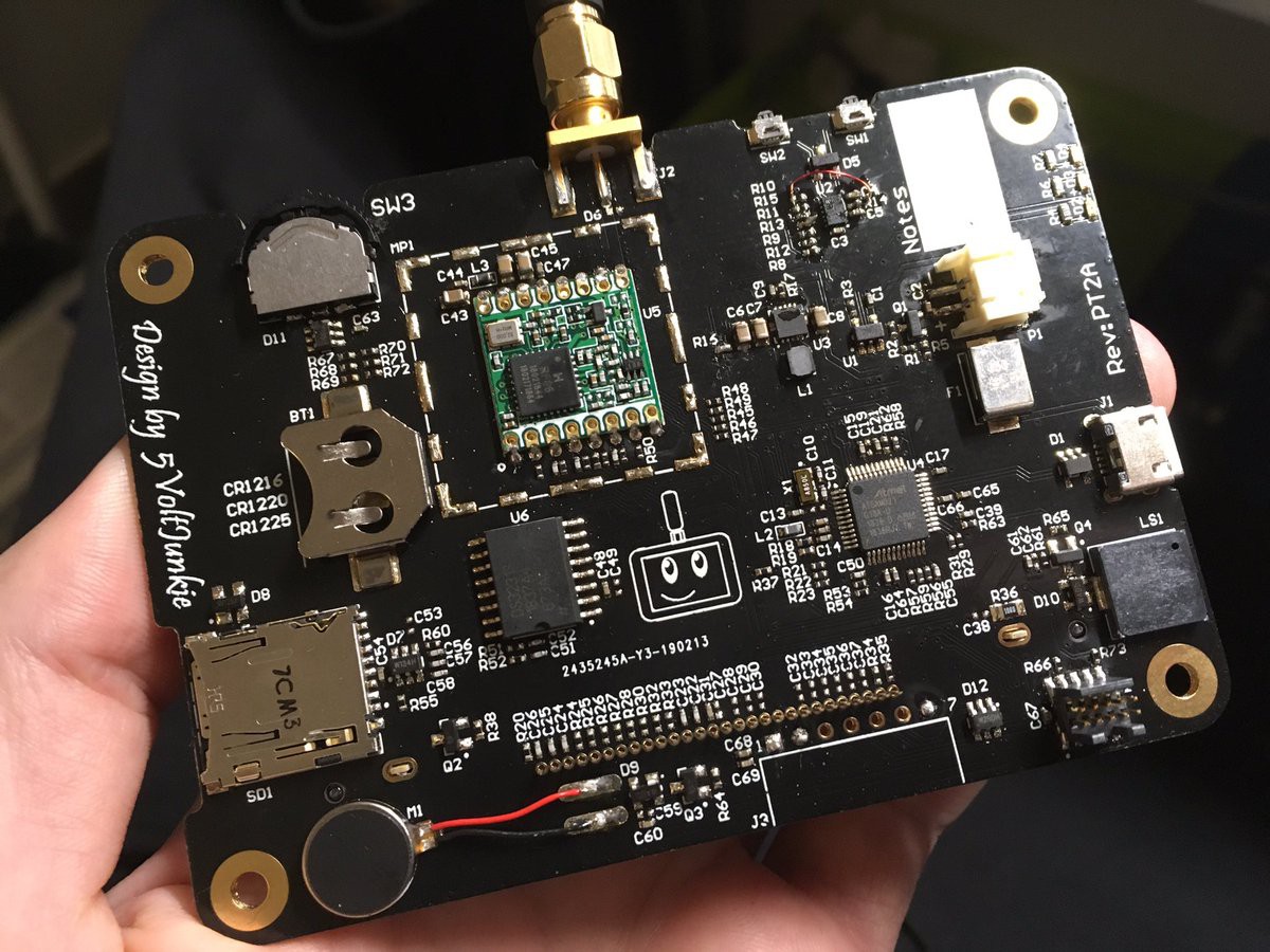
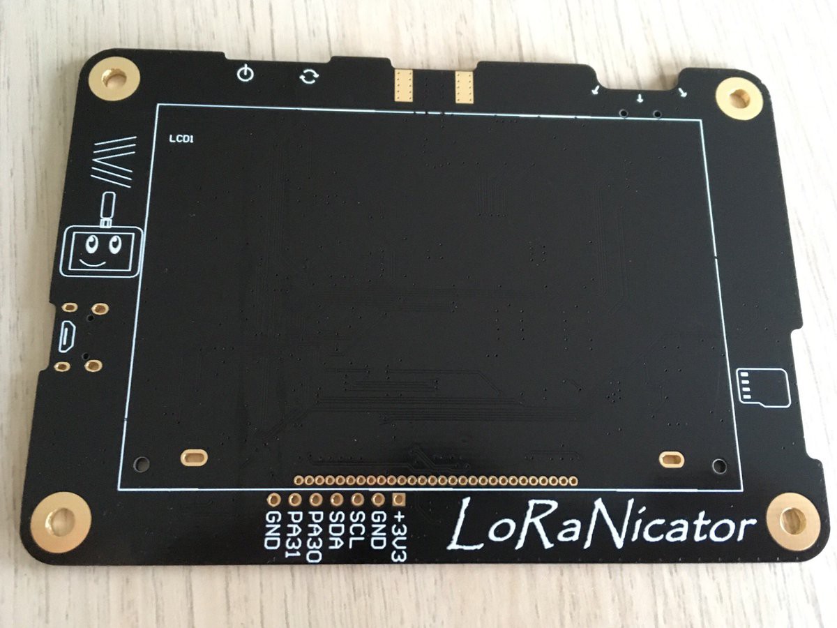
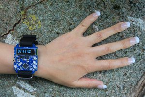
In the second version of the board, I wanted to keep the board Arduino compatible, but needed a better microcontroller, so I used a SAMD21 Cortex M0 (same on Arduino Zero MKR) microcontroller instead of ATmega328p. I was a bit unhappy with the Nokia display and replaced it with a bigger one. The availability of the AI-Thinker Ra-02 module isn't as good as the RFM95 and I also wanted to get rid of the U.FL connector. So the three main components were replaced and I needed some more features like LiPo Charger, real time clock, sd-card, a proper on/off circuit, navigation switch instead of common push buttons and a buck/boost-voltage converter. I also added some nice-to have things, eg. vibration motor and buzzer.

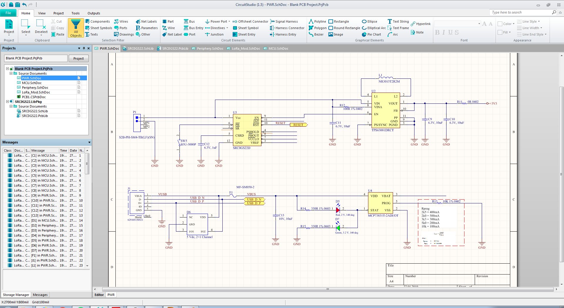
While designing the schematic, I decided to pick components, which I can get from the common big distributers for electronic components. I decided to choose all the components from Digi-Key, so I can save some shipping costs.

(I don't want to write the detailed hardware description here. For hardware details see the "LoRaNicator Hardware Description" below.)

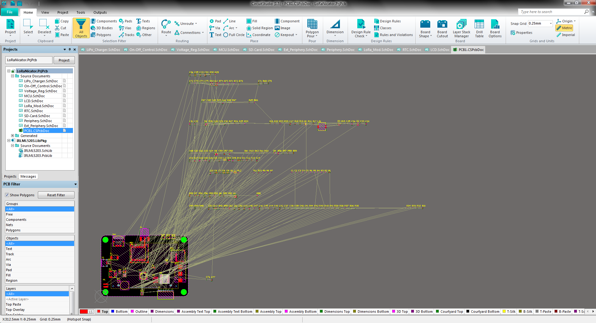
After 10 sheets of schematics drawing, I started to design the two layer board and configured the design rules first. I used following (significant) design specs which are compatible with the most pcb manufacturers (OSHPark, JLCPCB etc.)

Min. Trace Width / Clearance                    6.3mil (0.16mm)

Min. Via Drill / Outer Diameter                 10mil (0.254mm) / 20mil (0.508mm)

For the power rail I've chosen a thicker traces: ~23mil (0.6mm). There are two interfaces, where the impedance controlled design has been required. The antenna trace and the USB differential pair.

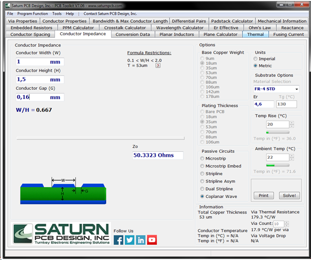
For those kind of trace design I like to use the PCB Toolkit. Since the board is a two layer design, with 1.6mm thickness, I neglected the USB differential pair to avoid crazy thick traces. The USB traces are pretty short, so it shouldn't make any trouble.

I only focused on the width of the antenna trace. The transmission-line I decided to go with, is coplanar waveguide with ground plane (GCPW). I entered the substrate thickness of the pcb (1.5mm / 59mil) and the overall clearance 0.16mm (6.3mil) and calculated 1mm (~40mil) for the trace width to get a 50Ohm impedance.


I also modified the signal pad of the SMA connector (same width as the trace) to match the 50R impedance. I added a rounded corners to the pad and added a copper cut-out at the edge, next to the signal pin. Furthermore I added a via fence around the GCPW.

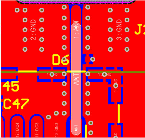
A good ground connection is also a factor to improve the HF design. So I created a special design rules in CurcuitStudio, to make a solid connection to GND pins of SMA connector and the RFM95 module. The ground connection for all the other components has the relief connection format

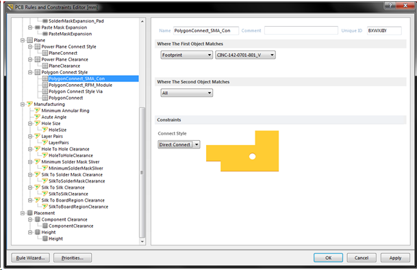
Also placed a lot of vias, for direct connection to the ground plane on the other side of pcb. Maybe it will improve the HF performance or maybe not, but I placed a shield can over the RFM95 module.

After designing the schematics and pcb, I ordered the board and a stencil for reflow soldering. The boards came with a gold finish and black solder mask and looked pretty nice :)


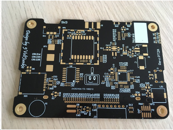
There are about 180 components on the board and many resistors and capacitors in 0402 package. So I didn't want to solder...
Read more »

CircuitStudio_Project_Package_HaD.zip

Altium CircuitStudio Project (Schematics, PCB)

x-zip-compressed - 2.91 MB - 03/17/2019 at 11:05

Download

x-zip-compressed - 166.57 kB - 03/17/2019 at 10:41

Download

step - 8.43 MB - 03/17/2019 at 10:24

Download

  • 1 × RFM95W Low Power Long Ra nge Transceiver Module
  • 1 × ATSAMD21G18A-AU‎ Microchip MCU 32BIT 256KB FLASH 48TQFP
  • 1 × Navigation Switch COM-08184 COM-08184
  • 1 × Vibration Motor 316040001
  • 1 × LCD COG GRAPH 128X64 Graphic LCD Display Module Transflective Black (White - Inverted) FSTN - Film Super-Twisted Nematic Parallel/Serial 128 x 64 NHD-C12864LZ-FSW-FBW-3V3‎

View all 11 components

  • Working on a case for LoRaNicator

    5Volt-Junkie04/03/2019 at 20:35 0 comments


  • Example Code

    5Volt-Junkie03/25/2019 at 18:32 0 comments

    Some people asked if I already published the LoRaNicator source code. At the moment I don't have a LoRaNicator specific code. There are just two example codes merged together and modified . The RFM95 example code from Adafruit und the display example code from u8g2 lib.


    See Adafruit Tutorial for a transmitter setup.

    If you still want to see my actual code, you can find a snippet here

    That's it!

    For tests with RTC, SD-Card, navigation switch etc, I just used Arduino example codes.

    I'm not a programmer and my source code for AVR microcontrollers was always bad. Now, the SAMD21 is completely new for me and I've to figure out a couple of things and have to RTFM ;-)

  • LCD and a new On/Off Controller

    5Volt-Junkie03/08/2019 at 10:28 0 comments

    Successfully tested the display. Also ordered a different type of On/Off-controller, which expects a feedback from microcontroller within >10 seconds instead of 2 seconds.


  • First board tests

    5Volt-Junkie03/04/2019 at 16:13 0 comments

    Started testing the hardware. Need another On/Off-controller since the current model allows only 2 seconds time frame for the feedback from microcontroller and the SAMD21 with Arduino bootloader needs ~2.5 seconds for booting and setting the GPIO to High.

     Following initial tests passed (tested with example codes)

     - RFM95 module

     - I2C RTC (fixed a mistake in routing of I2C. SDA and SCL were swaped :(  )

     - uSD-card

     - LiPo charger

     - programming over USB


    Next steps:
    - order some missing parts (capacitors for the display)
    - test display :-)

  • PCBs arrived :)

    5Volt-Junkie02/28/2019 at 16:37 0 comments


  • Green light for pcb layout

    5Volt-Junkie02/08/2019 at 18:49 0 comments

    The schematic is almost done. Just need to add some information to part properties. Now I can start with the PCB design. The dimensions of the board will be about 100x70mm big (3.9x2.76inch).

    I already ordered a couple of components, because I had to create some libraries and it's also a good feeling to having some real components while working on the project :-)

  • Starting with power

    5Volt-Junkie01/27/2019 at 21:35 0 comments

    Started with the power management today. A couple of month ago, I found a very interesting ic from ST, the SRC0. It's a small on/off controller, which can be connected to a SMPS, so the power supply can be enabled / disabled by a simple press of the push-button. Furthermore it has an input for external signal, to disable the power (e.g. from microcontroller).


    For the SMPS I would like to use the TI TPS63001 buck-boost converter. It provides a fixed +3,3V voltage output @ >1000mA current output (Vin = 2.6 - 4.2 VDC).
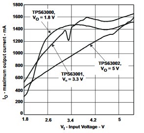
    In this voltage range and at ca. 100mA load, the efficiency stays >90%, which is not so bad :)

    For the charging circuit I'll use MCP73831. The circuit will be powered by 1 LiPo cell.

  • Start

    5Volt-Junkie01/26/2019 at 23:33 0 comments

    After playing around with the first Prototype of LoPSy (LoRa Paging System ;-) ) and the first range test went well, I wanted to start with a new hardware revision.

    The first hardware prototype contained a Nokia display, AI-Thinker Ra-02 433 MHz LoRa module and an ATmega328 µC. 

    For the new hardware revision I would like to replace the mentioned components and add few more functions.

    Some requirements:

    • SMPS instead of linear regulator
    • 1-cell LiPo charger IC
    • ATSAMD21 microcontroller (compatibility with Arduino Zero MKR (and Adafruit Feather?))
    • Get rid of the Nokia Display
    • uSD-card
    • tiny pager motor
    • buzzer
    • to be defined...

View all 8 project logs

Enjoy this project?

Share

Discussions

Davinder Chandhok wrote 12/23/2020 at 12:00 point

Can I make one just from the included files? I live in Germany, how much do all the components cost?

  Are you sure? yes | no

5Volt-Junkie wrote 04/06/2019 at 15:35 point

LoRaNicator communicates over LoRa only. There is no WiFi or BLE on board. 

  Are you sure? yes | no

Similar Projects

Does this project spark your interest?

Become a member to follow this project and never miss any updates