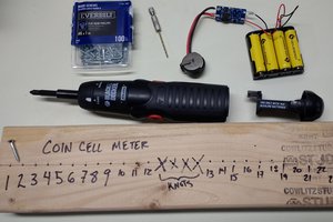
 Daren Schwenke
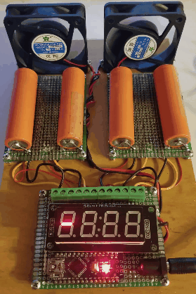
What is this for?
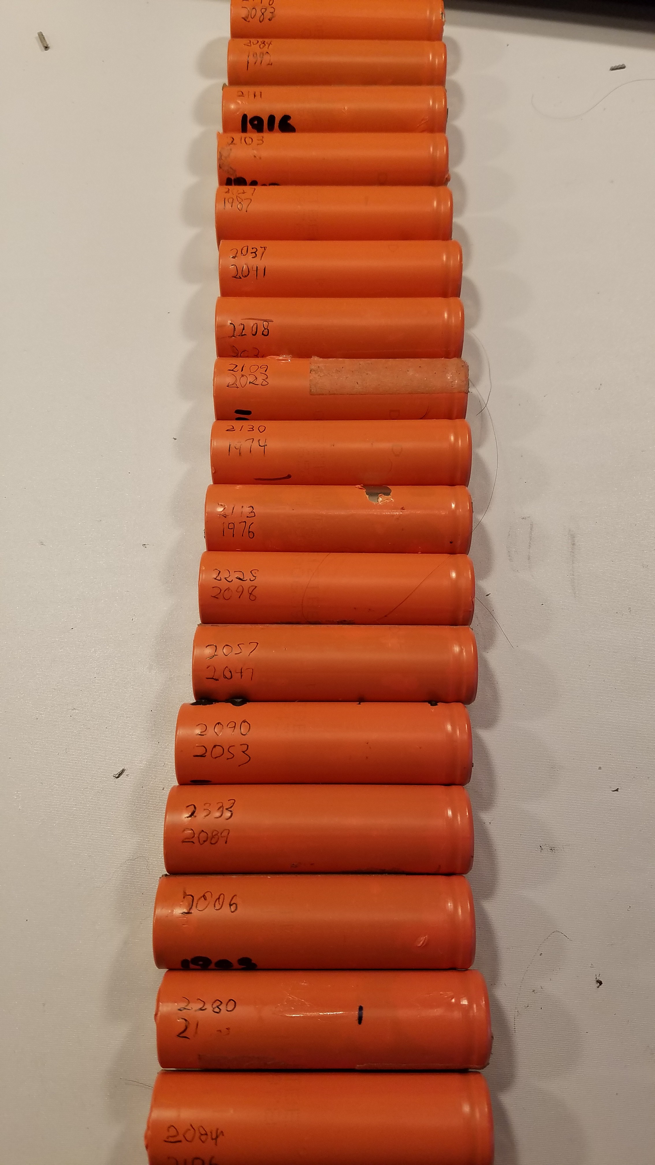
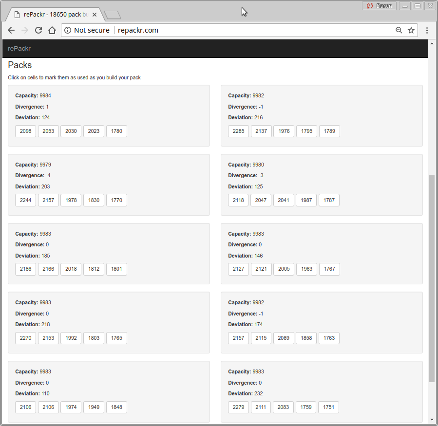
Li-Ion battery packs are arranged with cells in parallel to increase current, and then groups of those in series to increase voltage. So a 10s5p pack has 5 cells in parallel, and 10 sets of those in series.
To build a battery pack that you can charge and discharge quickly, it has to be balanced. The total mAh capacity for each parallel bank of cells needs to match the total mAh capacity of every other parallel bank of cells. Why building a balanced pack matters..
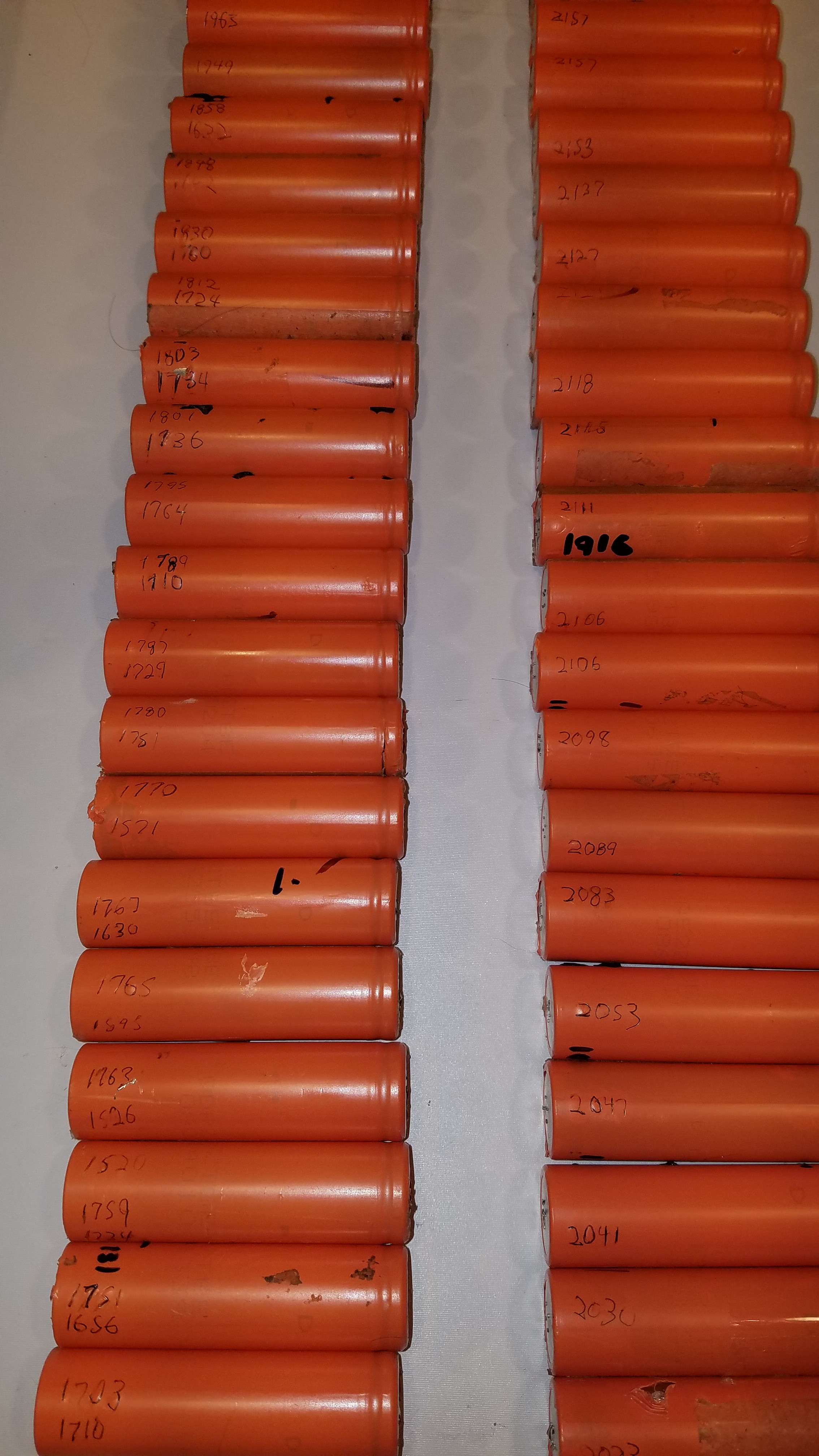
Fully charging and then discharging each cell at a known rate will give you the capacity. Then you can just play matchmaker to build your balanced pack. This is the discharger which gives you those used cell capacity numbers.
Constant current, mostly..
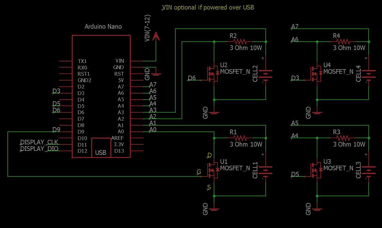
Normally as the battery voltage drops off, so would the current provided by a fixed value load resistor. This discharger monitors the current, and then adjusts the PWM duty cycle as need to maintain the target current. Current is directly measured as the voltage drop across the load resistor, so this consumes 2 ADC channels per cell.
The 3 ohm value of the load resistor was chosen to provide the target discharge current of 1A at the cutoff voltage of 3.0V. So over the voltage range of a fully charged cell to a fully discharged cell, this results in PWM tracking from about 80% to 100%. Doing true DC constant current just takes a couple more components, but this then runs the mosfet in the linear range instead of switching. That produces a *ton* of heat. I prefer cheating.
You set the target discharge current and the starting PWM level in the .ino file. You will still need to calibrate for accurate results.
Usage
Discharging starts when you insert a cell. Cell voltage and accumulated mAh are displayed while discharging.
Discharge is stopped when a cell is discharged to 3V (or whatever you set) and the capacity in mAh is displayed. For a good cell, discharging takes about 2 hours.
Discharging will not restart again until the cell is removed to prevent cell recovery from starting another cycle.
Caveats
I'm sampling values which are directly connected to a running PWM source, so the input to the ADC is essentially one of two levels. To compensate for this and still get my desired analog reading, I'm oversampling the ADC inputs by a factor of 100x and then averaging. Works.
Safety?
There is no protection for reverse hookup, the mosfet gates are directly connected to the Nano with no pulldown resistors to prevent 'floating' inputs if turned off, the ADC pins are directly exposed to whatever you plug in... etc. There are tons of ways to improve this. That being said, as long as you don't put the cells in backwards, everything should work just fine for the foreseeable future. Eventually you will screw up and destroy the Nano. Twenty minutes later you will have a new one in its place.
This project is all about turning battery power into heat, and will need to continuously dissipate 12W. Make sure you have somewhere for that heat to go. Discharging at just 1A can still cause 'bad' cells to heat up, which can turn them into little rockets. I added the fans to keep my nichrome wire load resistors cool, but keeping the batteries cool isn't a bad idea either. Be safe.


 Ted Yapo
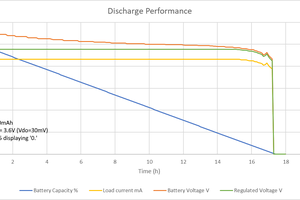
 George
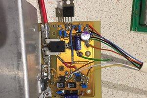
 Saabman
Nice! I am running this right now. Just a couple of suggestions on the hand drawn schematic. The symbol is correct, but it looks like the S and D identifiers are swapped? Also, D9 controls the PWM for analog inputs A0/A1. Thanks for posting this project