The Power Stage Variations
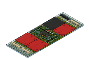
The reason why PowerPACk32 was designed as two different boards was to make it easy to deal with the different topologies. Although a 2 board solution is often undesirable, when experimenting there are a few advantages worth mentioning:
- The Microcontroller side of things was implemented in a 4 layer board, whereas the 2 layer board was generated in a 2 layer copper clad. If the entire solution had been implemented in a single board, then the entire PCB would have had to be either 4 layers or 2 layers.
- By splitting the module, I was able to design one FET board with single shunt and one FET board with three shunts (SENSE resistors). If a different topology was to be implemented (i.e. two shunts for phases U and V and a single shunt for total current; or using TO247 package FETs) I can easily modify the entire solution by simply changing the FET board.
- While experimenting/developing code for many different motors, I may need to change SENSE resistors, FETs, voltage dividers, etc. multiple times. Instead of physically changing these components on a single board, I can have multiple boards with different configurations which I can plug and play in seconds. Had the solution been a single board, I could also have multiple boards with different configurations but you can see how the stock gets bulkier really quick...
On PowerPACk lingo, the MCU side is always called the Brain board and the FET module, the FETs board. For this project you will see there is a 4 Layer Brain board and two different versions of the FET board.
The Voltage Range:
PAC5232 was designed for higher voltage applications. As the market has started to see an increase of 40V, 56V and 80V batteries (mostly for garden tools, as well as mobility solutions), there was a need for a device capable of operating at voltages much higher than the 72V the PAC5223 is rated at. The PowerPAC32 module starts to operate at around 25VDC. Most components are rated at 200V (electrolytic caps, FETs, etc), yet the Abs Max is 160VDC. The module does not have an Over Voltage protection. For 56V application, 160V represents almost 3X worth of headroom which is more than plenty when considering voltage transients.
Current Handling
The TO220 MOSFETs employed on the module are 200V 65A switches. The PowerPACk32 PP_TO220_xS module was designed with enough space to allocate a heat sink. It is of crucial importance for the system's thermal impedance to be minimized. As part of this project, I will present a model for the thermal heat sink air foil which I plan to utilize. Maximum Current will be measured once this component is implemented.
Motor Control Topologies
The PowerPACk32 module can drive tri phase BLDC motors in either Hall Sensor or Sensorless mode. For Hall Sensor, PAC5232 Timer Input captures are used to gather hall sensor commutation point as well as opcode. For Sensorless mode, phase output voltages divider are compared against the center tap to obtain the BEMF crossing point and determine optimal commutation point. The exact same hardware can be utilized for either algorithm. Alternatively, tri phase PMSM motors running Field Oriented Control algorithms could also be driven. For this project I will provide support for BLDC with Six Step Trapezoidal control.
End Application
The foreseeable end application for the PowerPACk32 module is driving a small GoKart vehicle running at somewhere in between 48V to 60V.
 Marek
Marek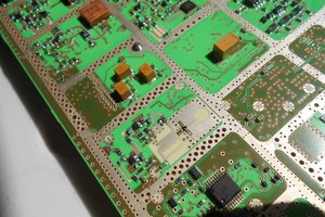
 Don Straney
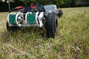
 Luke
Luke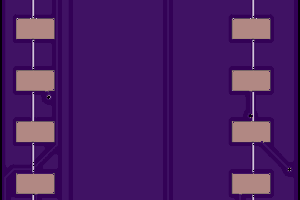
 Bob Coggeshall