 Josh Cole
Build Instructions
This is a very brief explanation of how to piece together the hexagons. It is not technically difficult, just very time consuming.
- Print the parts:
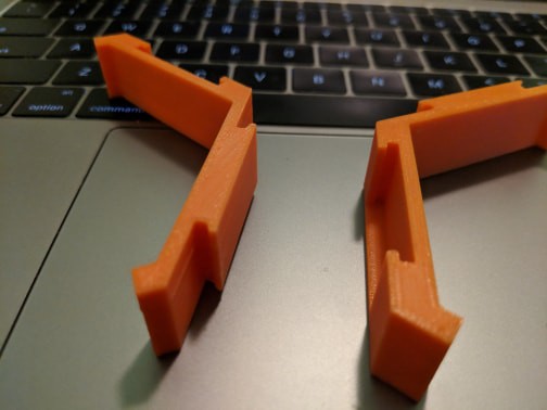
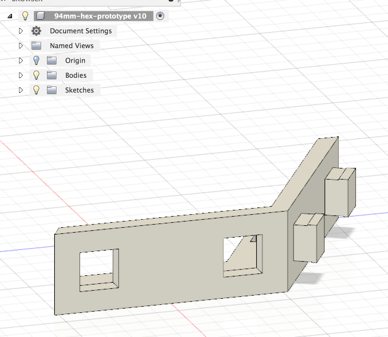
- Base Hexagon Piece
- Faceplate
- Diffraction Insert
- To assemble a single hexagon
- Take the core unit
- Attach the faceplate to the front of it, snapping it completely inside
- Reverse the part
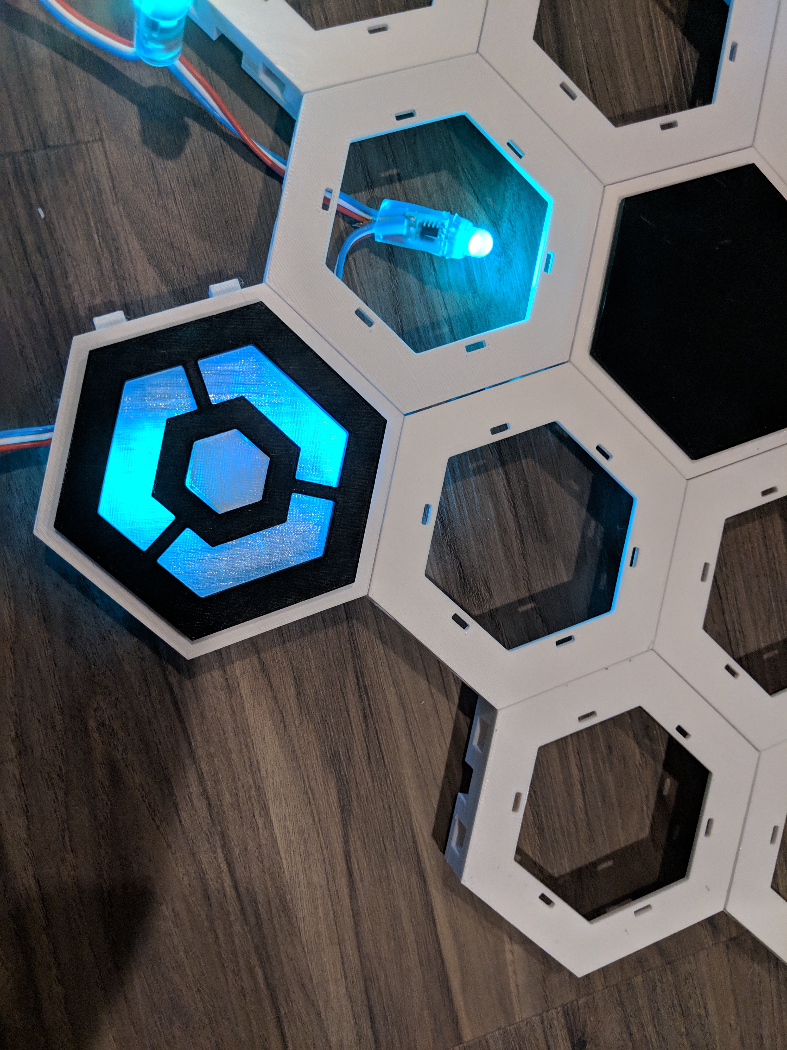
- Take the clear diffraction insert, snap it on the inside (against the faceplate leads). You will know it is correct if the small hexagonal shaped inner piece is flush with the faceplate once fully merged.
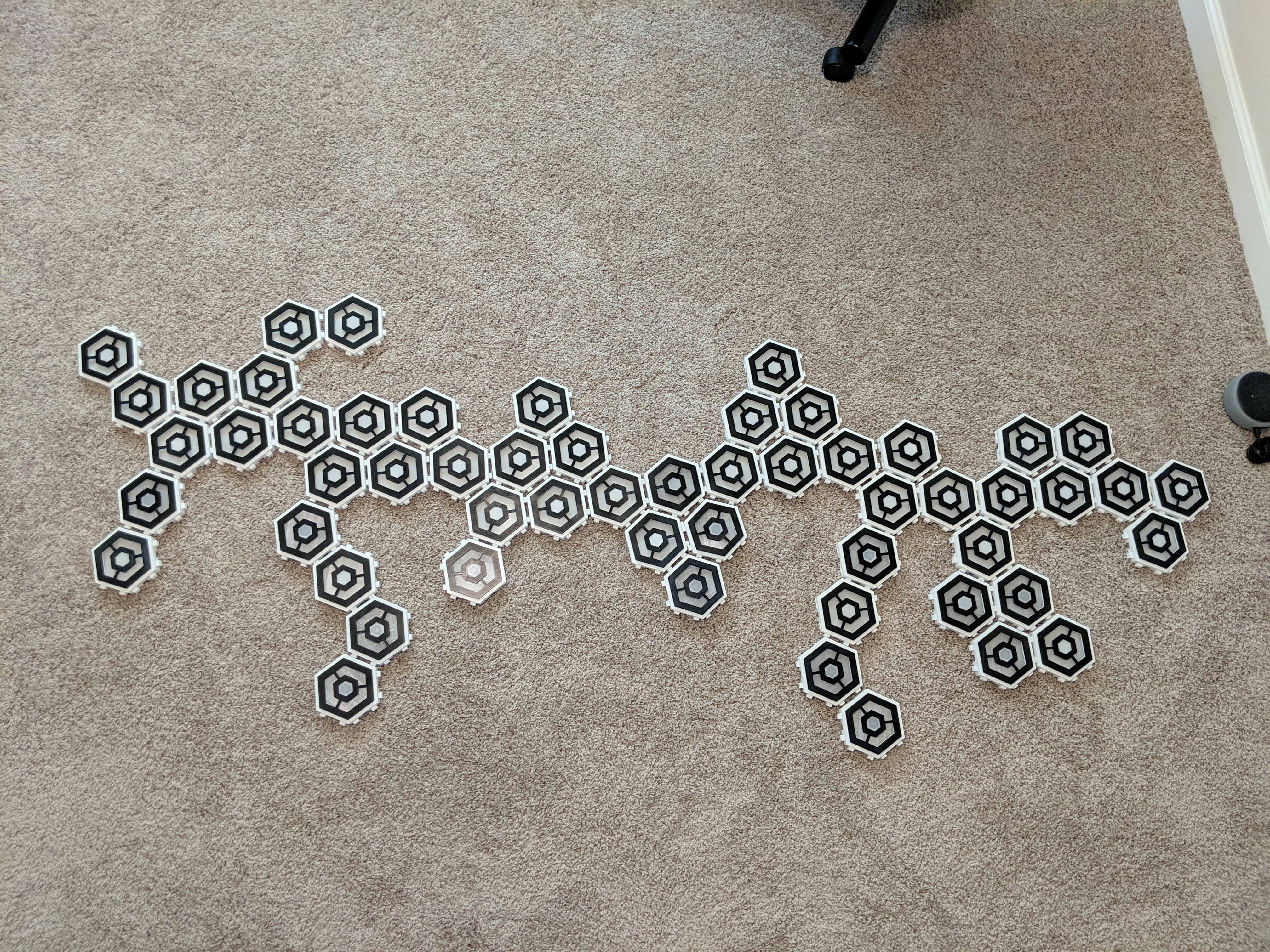
- Assemble each hexagon individually before connecting together.
- Snap hexagons together by angling them with each other and pinching the joint with your fingers until they are solidly together.
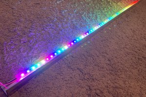
- Hot glue the light strand inside, passing it between each hexagon through the available channel.
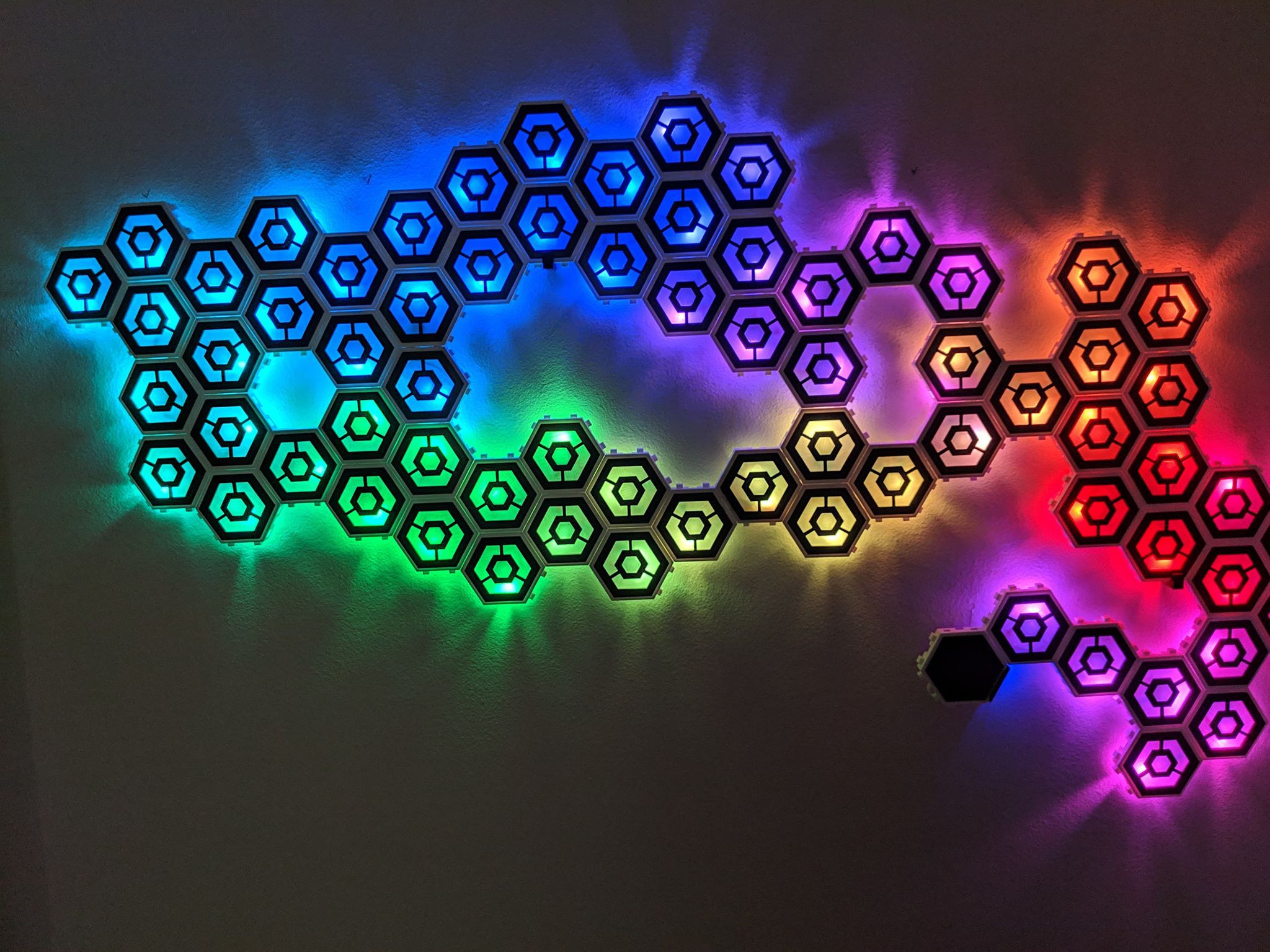
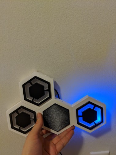
- For my hexagon wall, I decided to have 2 LEDs per hexagon. So I angled them such that the top of the light is facing roughly the middle of the hexagon unit. That seemed to create a very good dispersal pattern.
- For good measure, hot glue the joints between hexagons - or just in between each channel (as needed).
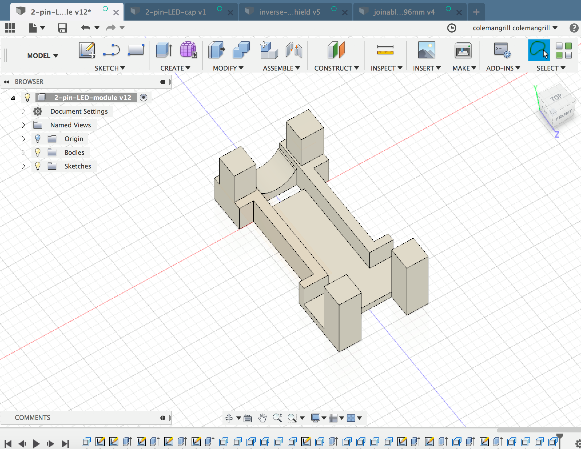
These lights operate on a single-wire communication channel. So just apply power/gnd/gpio as directed by the specific lights you're using.
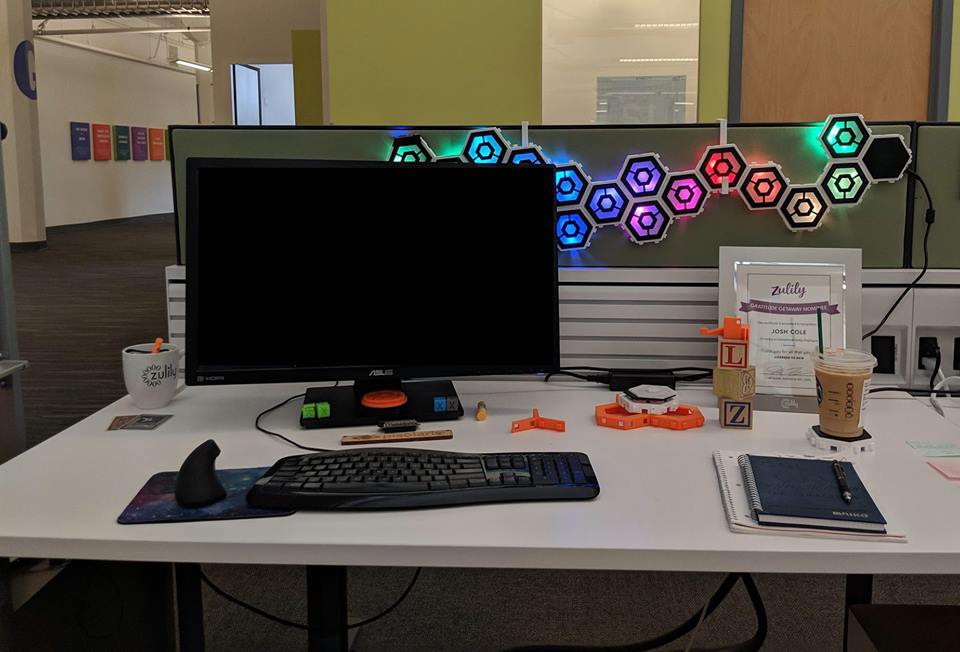
Do this 50 times and you've got yourself a wall!


 Jon Kunkee
 Eddie
Eddie
 todbot
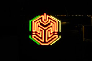
 swimmingthestyx
Instead of printing the diffuser have you thought of using polystyrene plates (they are pretty cheap on Ebay) and cut them to size. I messed around with WS2812 LEDs and polystyrene as a diffuser and the effect was quite nice.