0%
0%
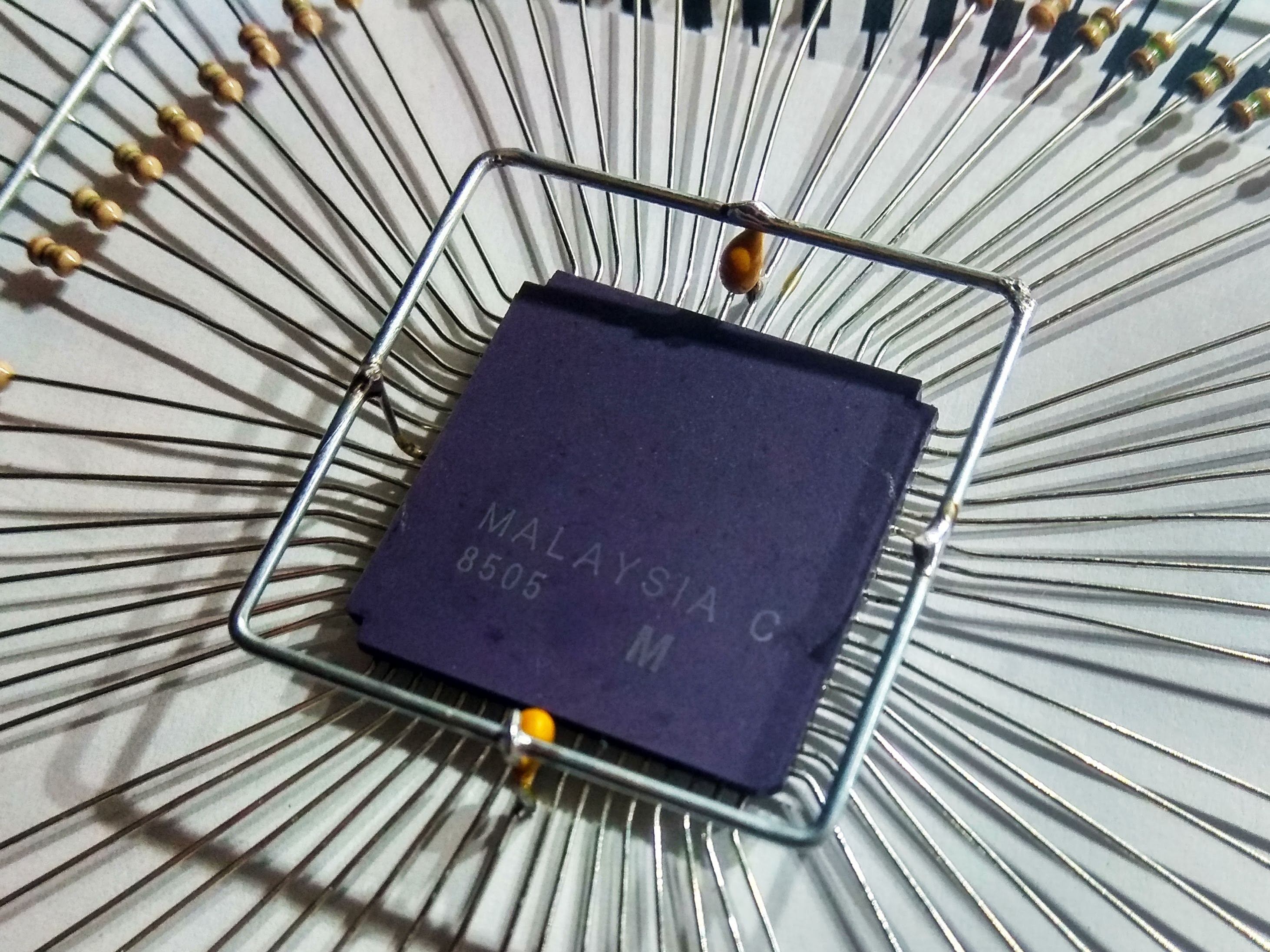
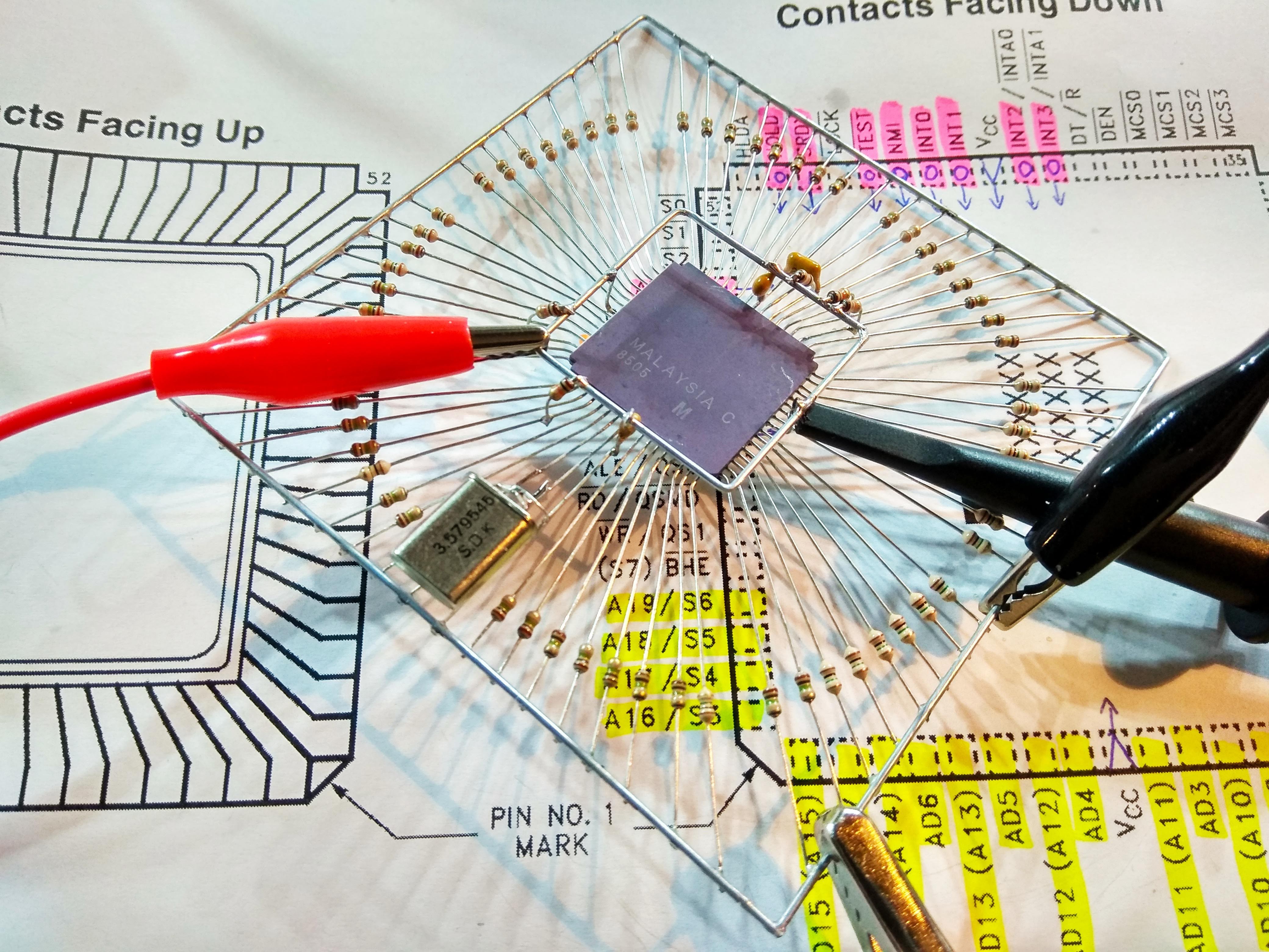
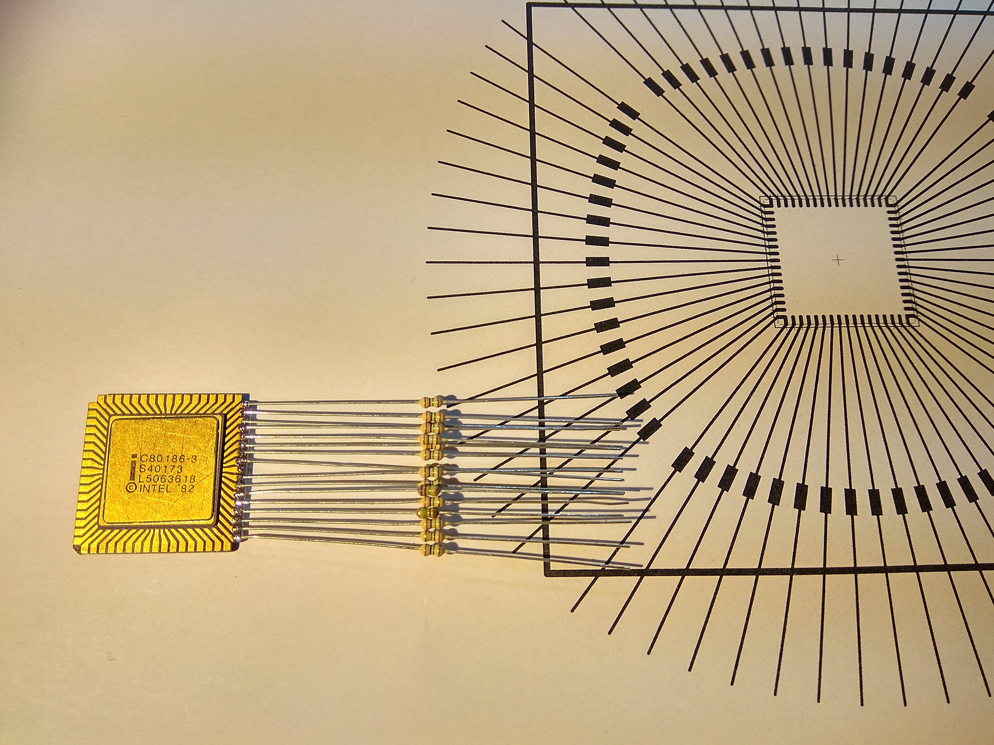
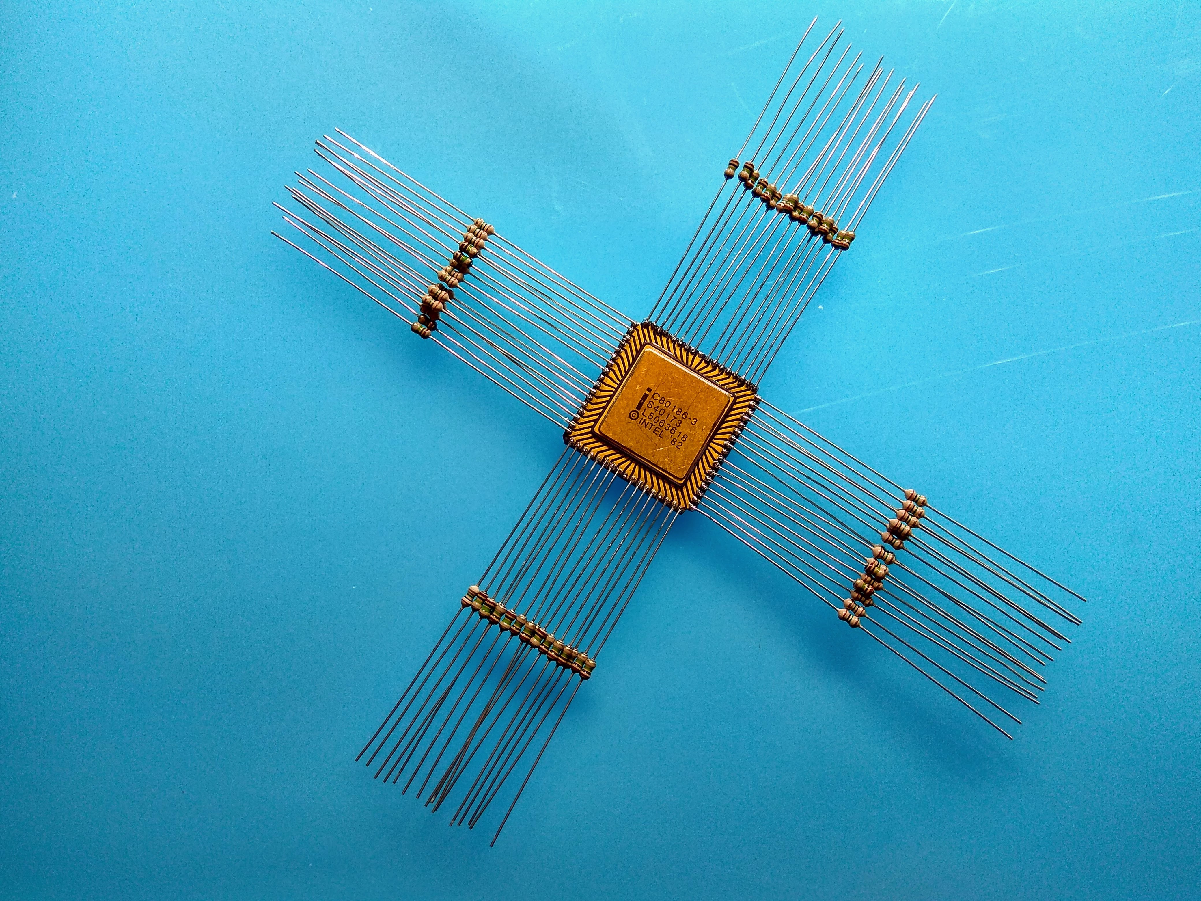
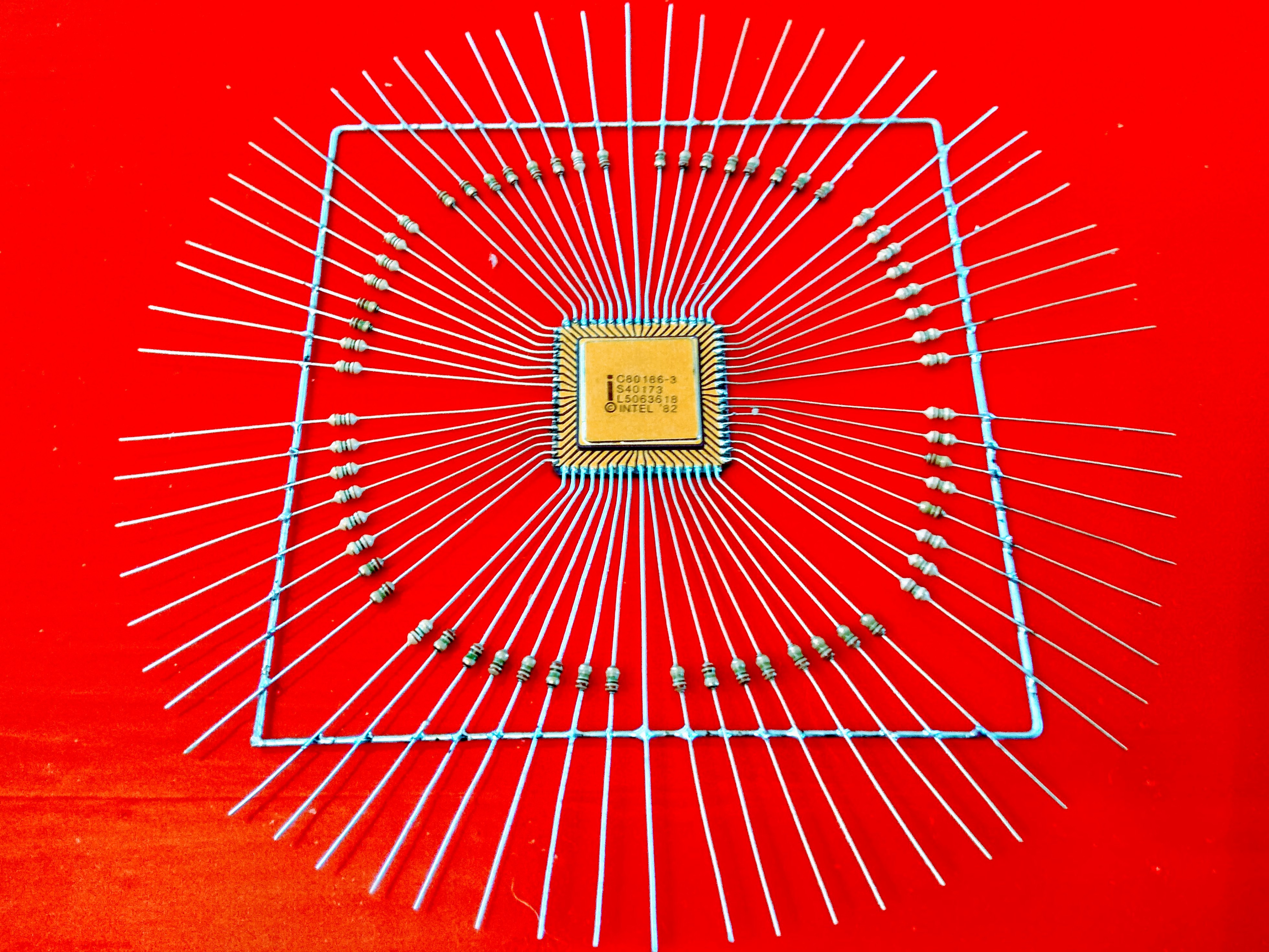
Gold186
A freeformed computer based on an Intel 80186 with 16 KB eprom, 1 MB ram and a serial port.
 matseng
Become a Hackaday.io member
Already have an account? Log in.
Just one more thing
To make the experience fit your profile, pick a username and tell us what interests you.
Pick an awesome username
hackaday.io/
Your profile's URL: hackaday.io/username. Max 25 alphanumeric characters.
Pick a few interests
Projects that share your interests
People that share your interests

 Benchoff
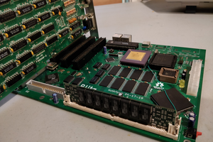
 Carson Herrington
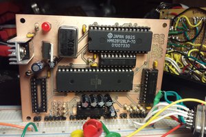
 Mars
Mars
Wow, I love it! You don't see much love for the 80186, and this is a great way to display it while putting it to work. Keep us posted!