 Stephen Holdaway
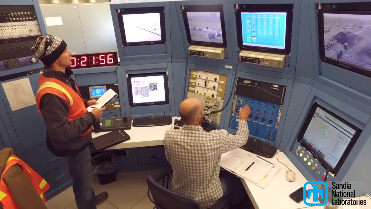
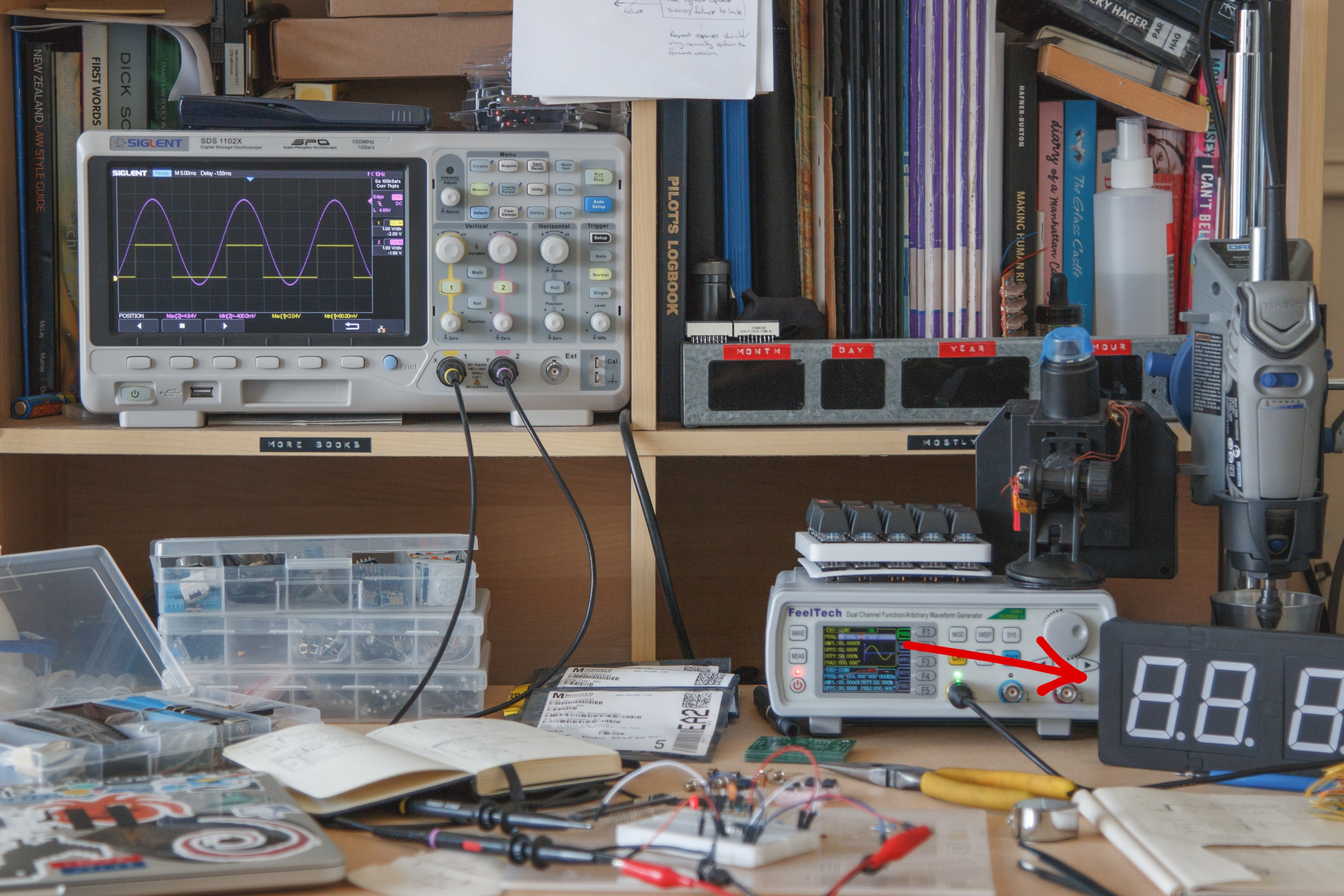
After reading Eric Schlosser's Command and Control: Nuclear Weapons, the Damascus Accident, and the Illusion of Safety a year ago and searching related topics, I found myself watching the video Rocket Sled Impact Test In Slow-Motion from Sandia National Labs. In the background of a couple of shots in this video, a large digital clock in the background caught my eye:
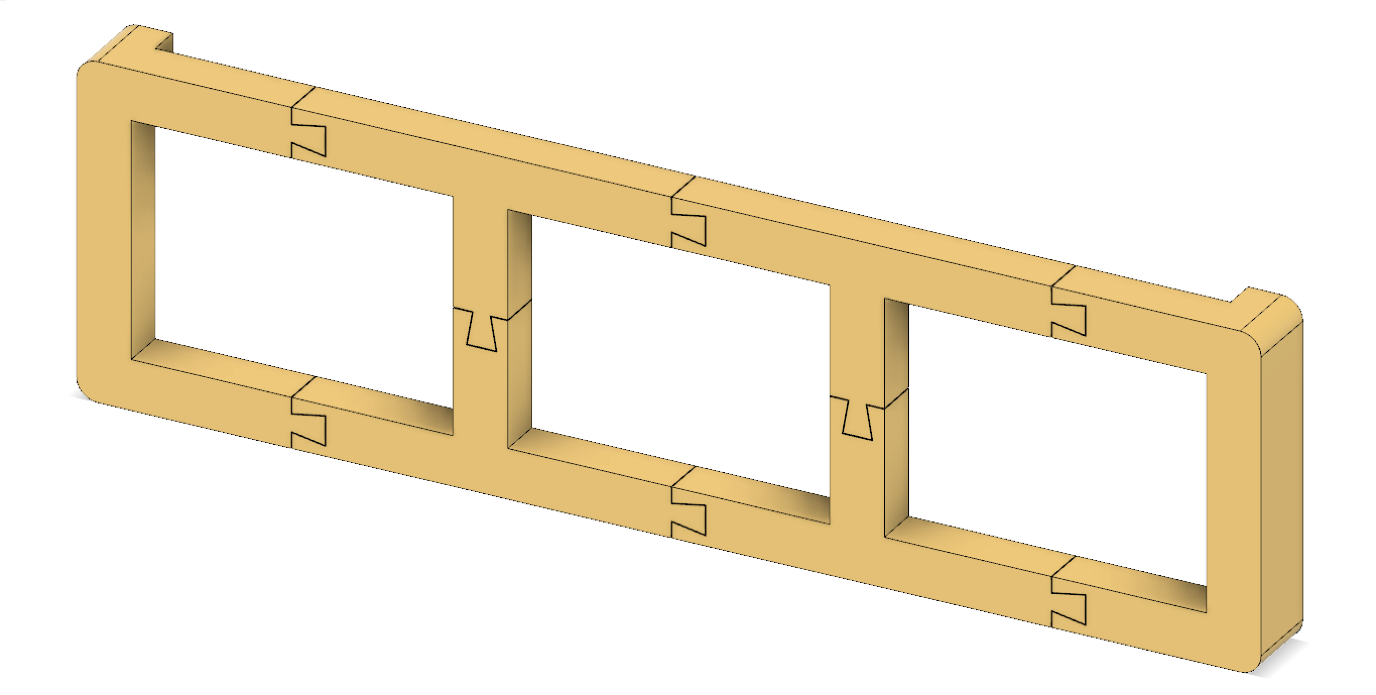
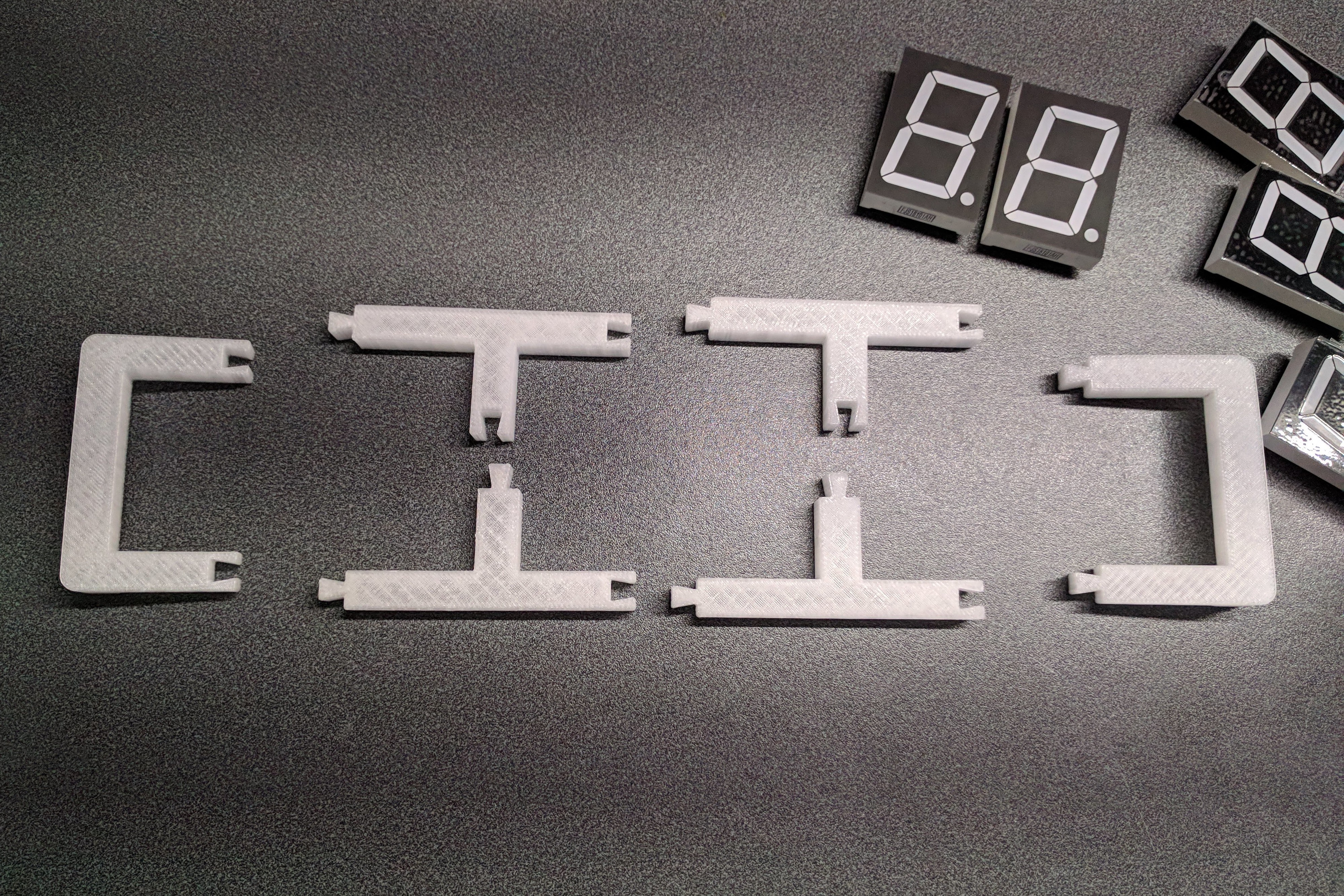
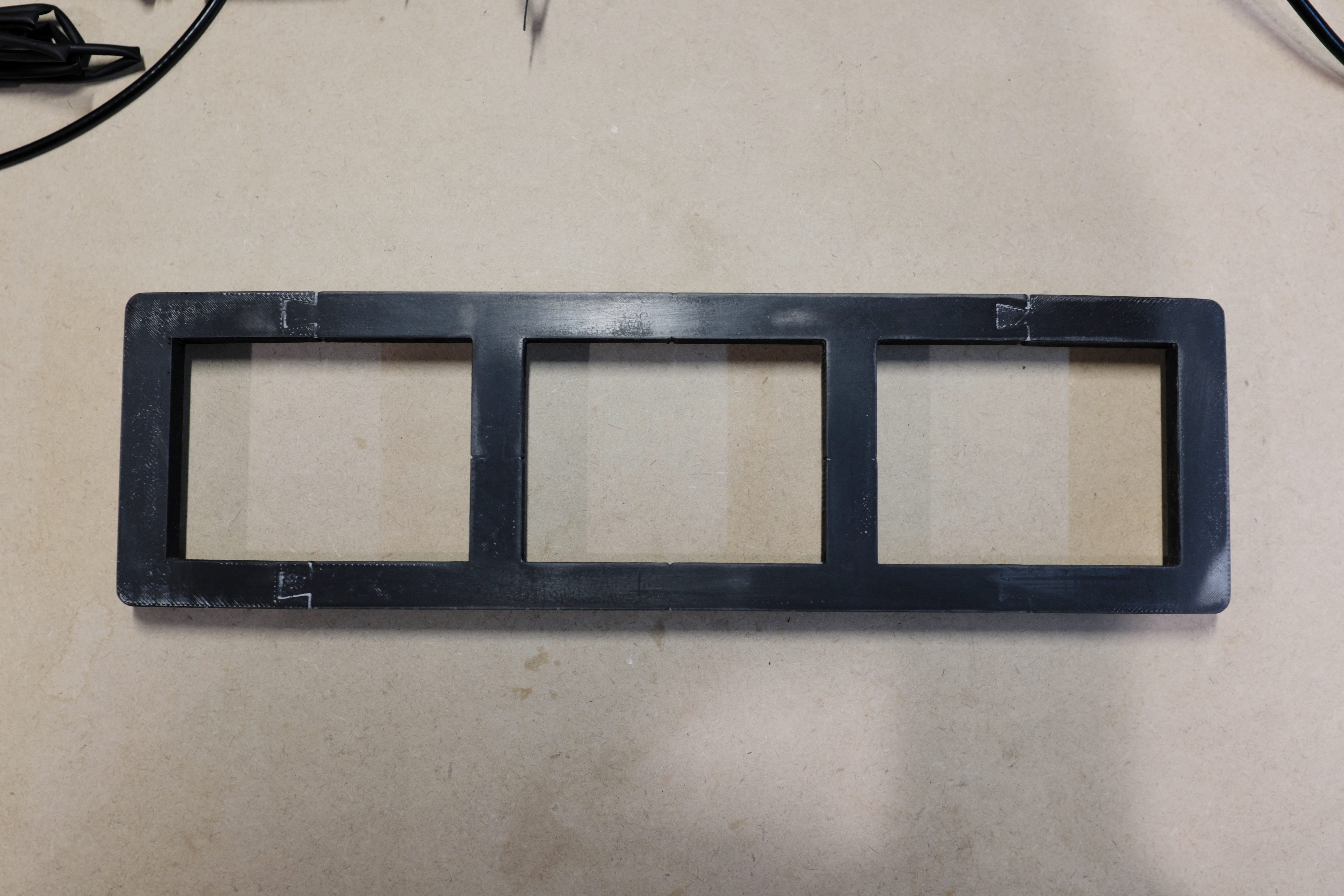
My initial "oh, that's cool" thought turned a few days later into buying a bunch of 1.8" 7-segment digits. When these arrived a month later in April 2018, I put together a frame in Fusion360 to mount them on the wall (sans any other plan, which is typical for me). The resulting 28 x 8cm design was far too big to print in one go, so I split it into 6 pieces joined with dovetails:
After printing in ABS, test fitting and bonding the joints using acetone, I gave the frame a quick sand and a paint job:
The initial results weren't ideal; the digits fit perfectly, but the dovetail joints were too obvious for my liking. I did another round of sanding and paint, then the frame and digits sat on my bench for a few months:
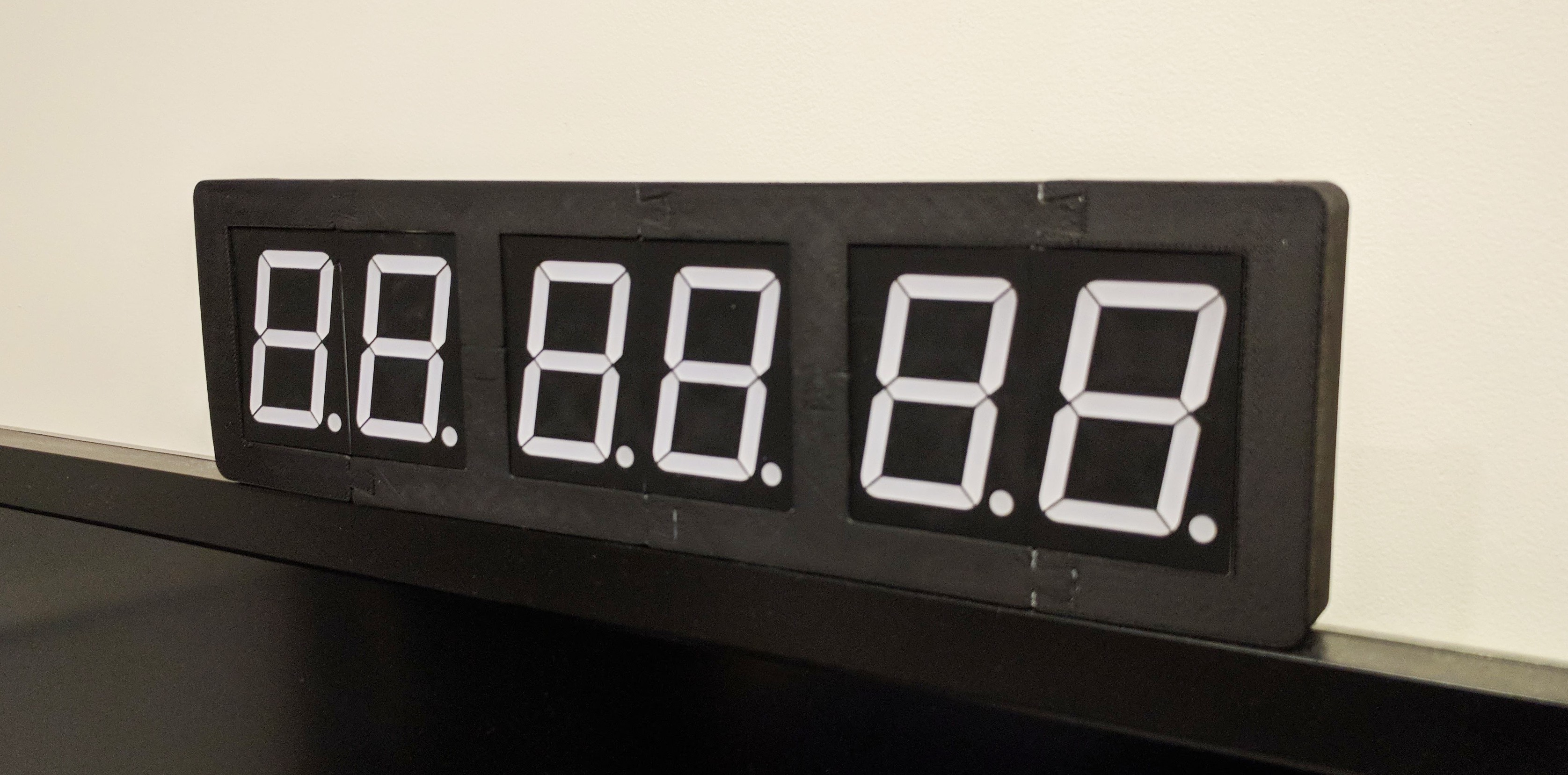
In July I had another go at sanding and painting the frame, this time using painters gap filler to fill in the gaps around the part joints. This worked much better:
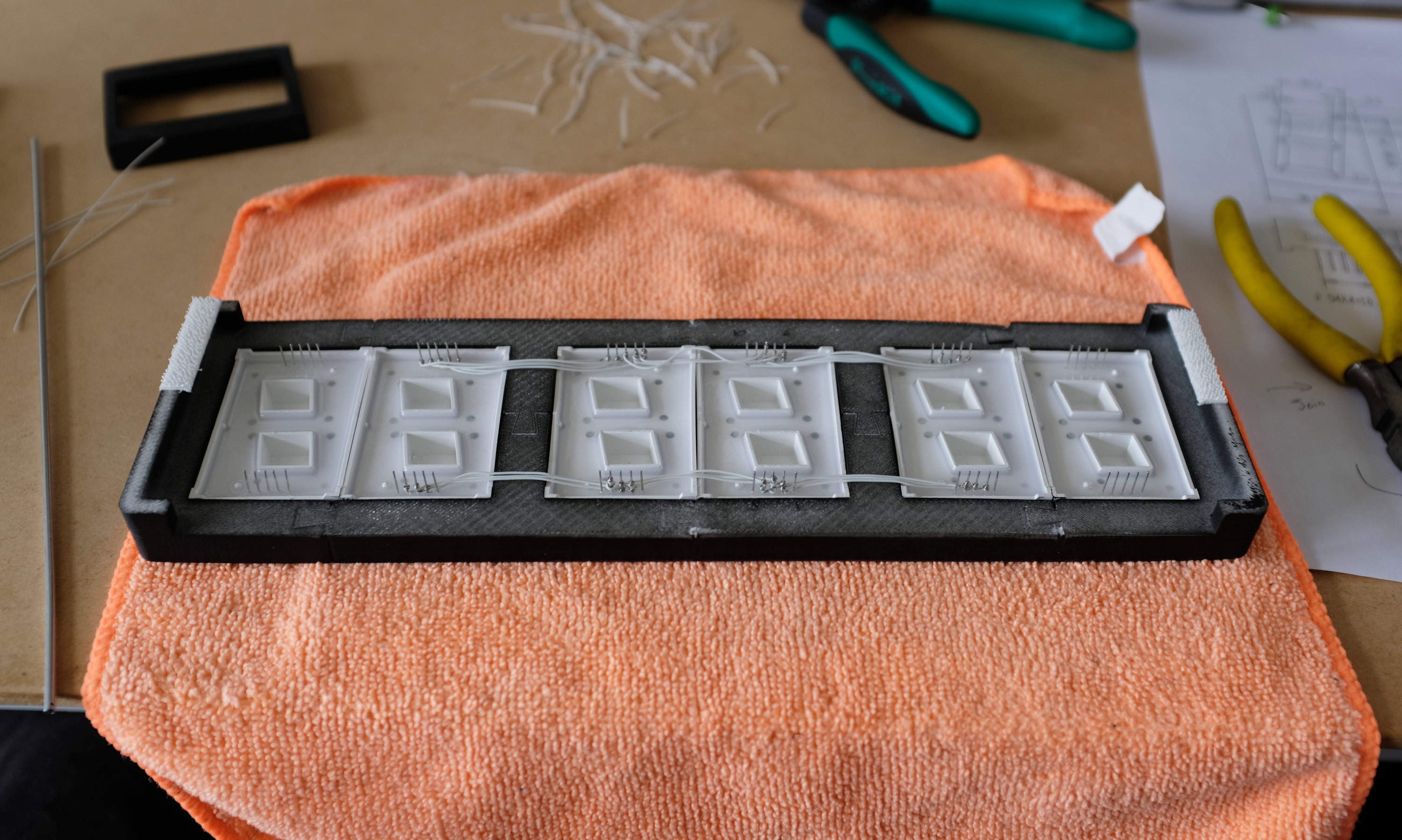
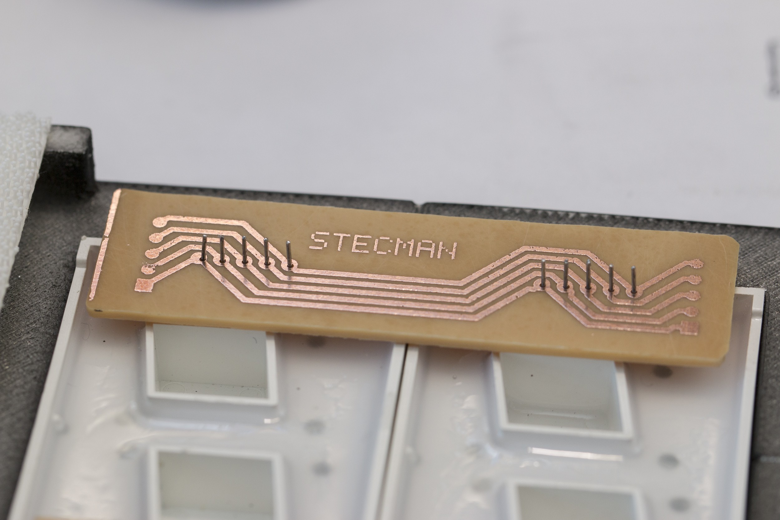
With the frame looking more polished, I wired up the displays using a home-made wire-wrapping tool:

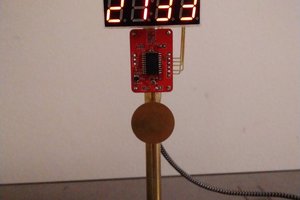
For the next while, this project lived on my desk driven by an STM8S and MAX7219 on a breadboard. Initially this only counted seconds (roughly) from the power on time, but later I calibrated the timing to have a semi-accurate clock that maintained the time given at compile+flash time. Code for this STM8 prototype is on Github for reference.
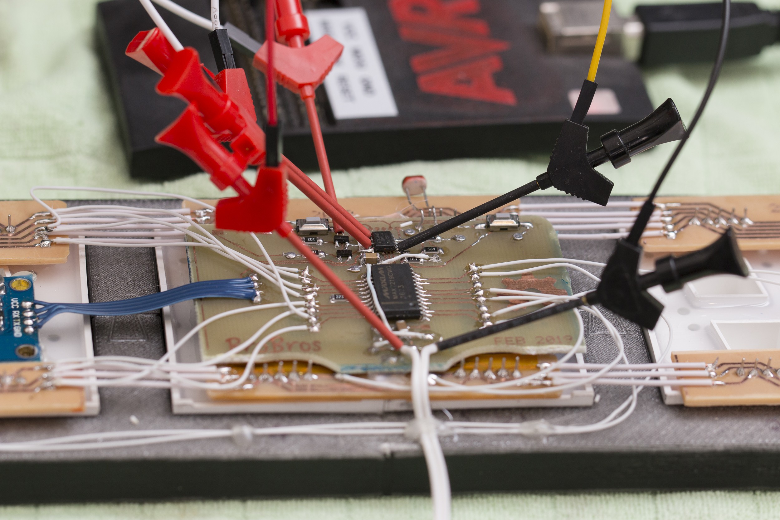
At this point I replaced the STM8 with an ATTiny13A and plugged in a NEO-6M GPS to read the actual time from. I'd worked out the Tiny could just support the number of I/O I needed, and some tinkering proved that the required C program could comfortably fit in the 1KB of available program space.
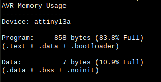
Working with the ATTiny13A for this was a bit of fun as it lacks hardware UART (for the GPS) and hardware SPI (for the MAX7219). Additionally, the NMEA sentences sent by the GPS are up to 79 bytes, which won't fit into the tiny's 64 bytes of SRAM.
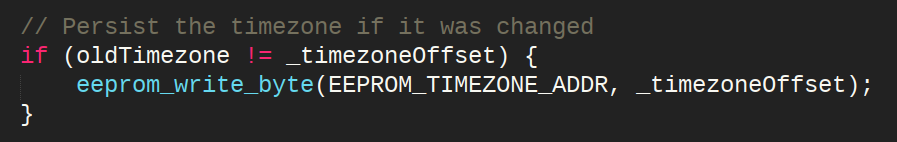
The code has a routine to find RMC ("Recommended Minimum") sentences in the GPS's serial output and extract time and date information with only a 2 byte buffer for converting the numbers represented in ASCII to 8-bit integers.
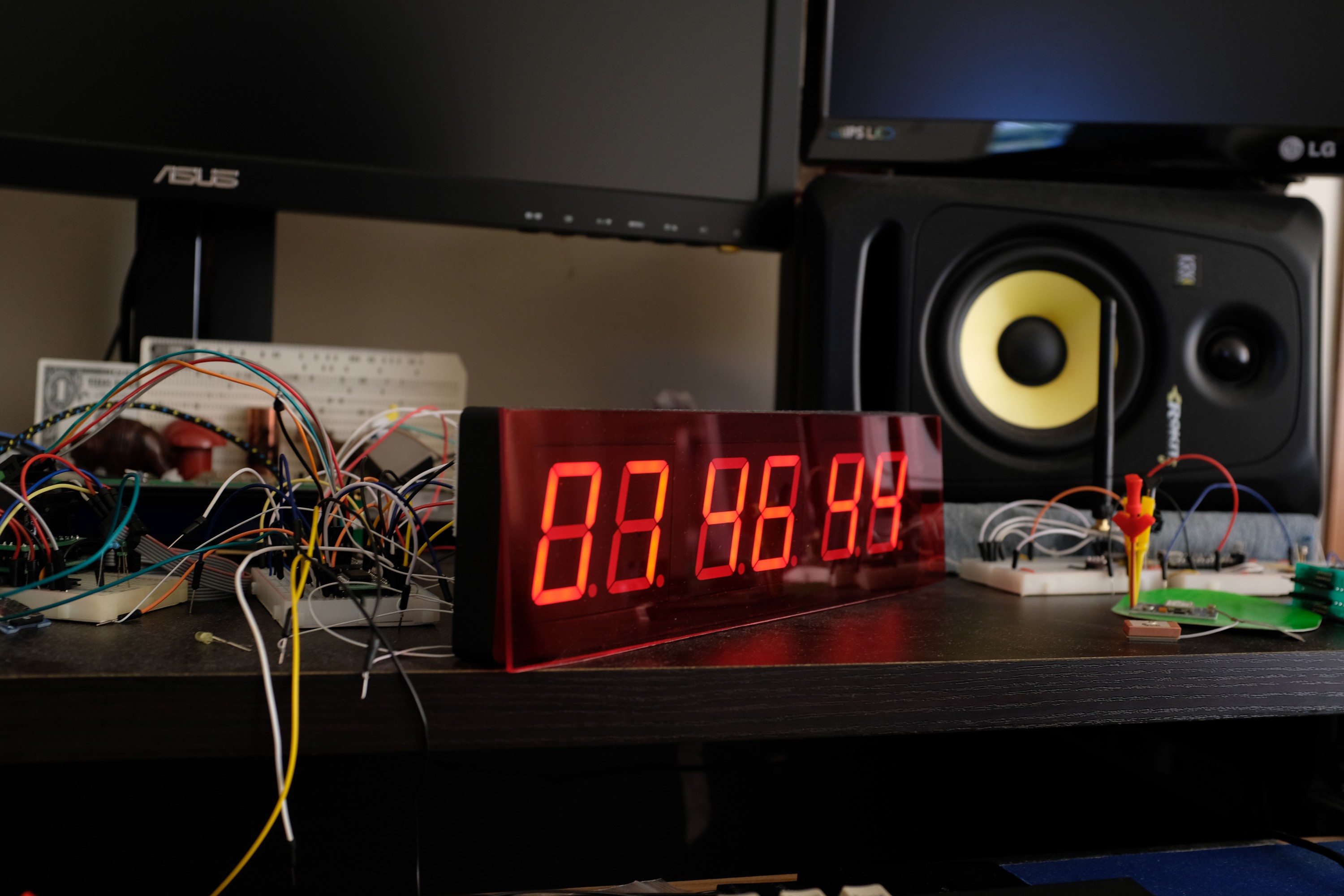
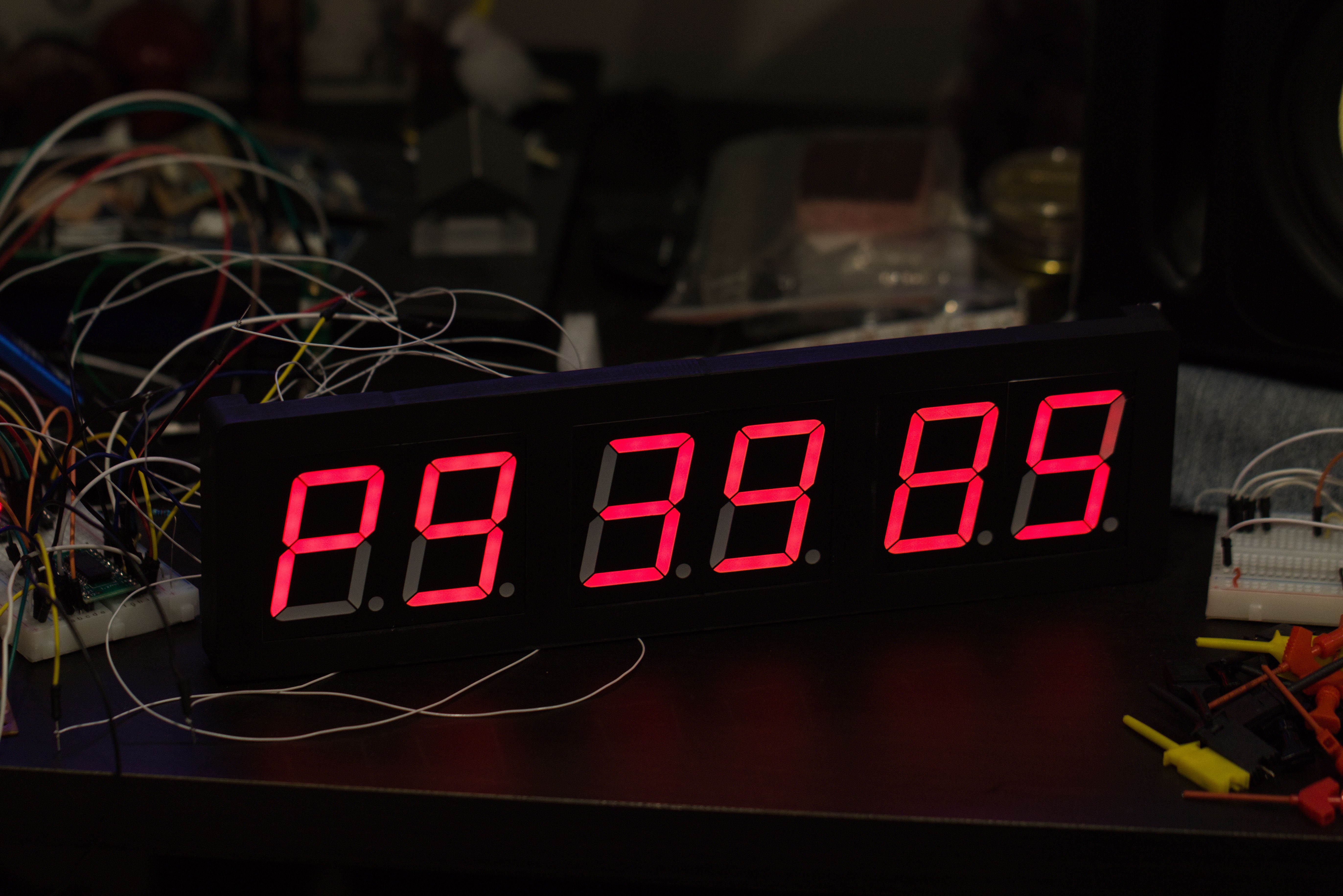
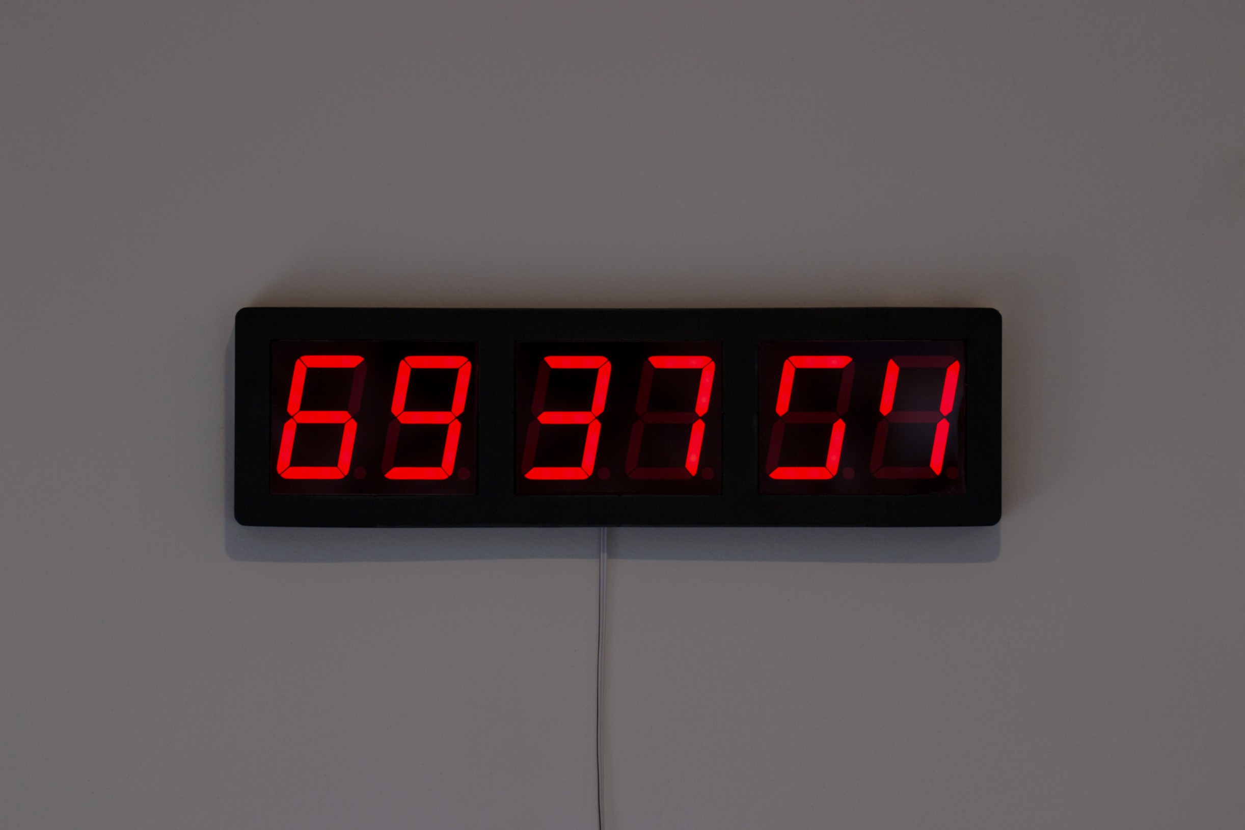
After turning the clock off for a week, my girlfriend mentioned that it'd been useful to have a clock (even if it looked like "a bomb timer from a movie"), so I thought I'd finish it off.
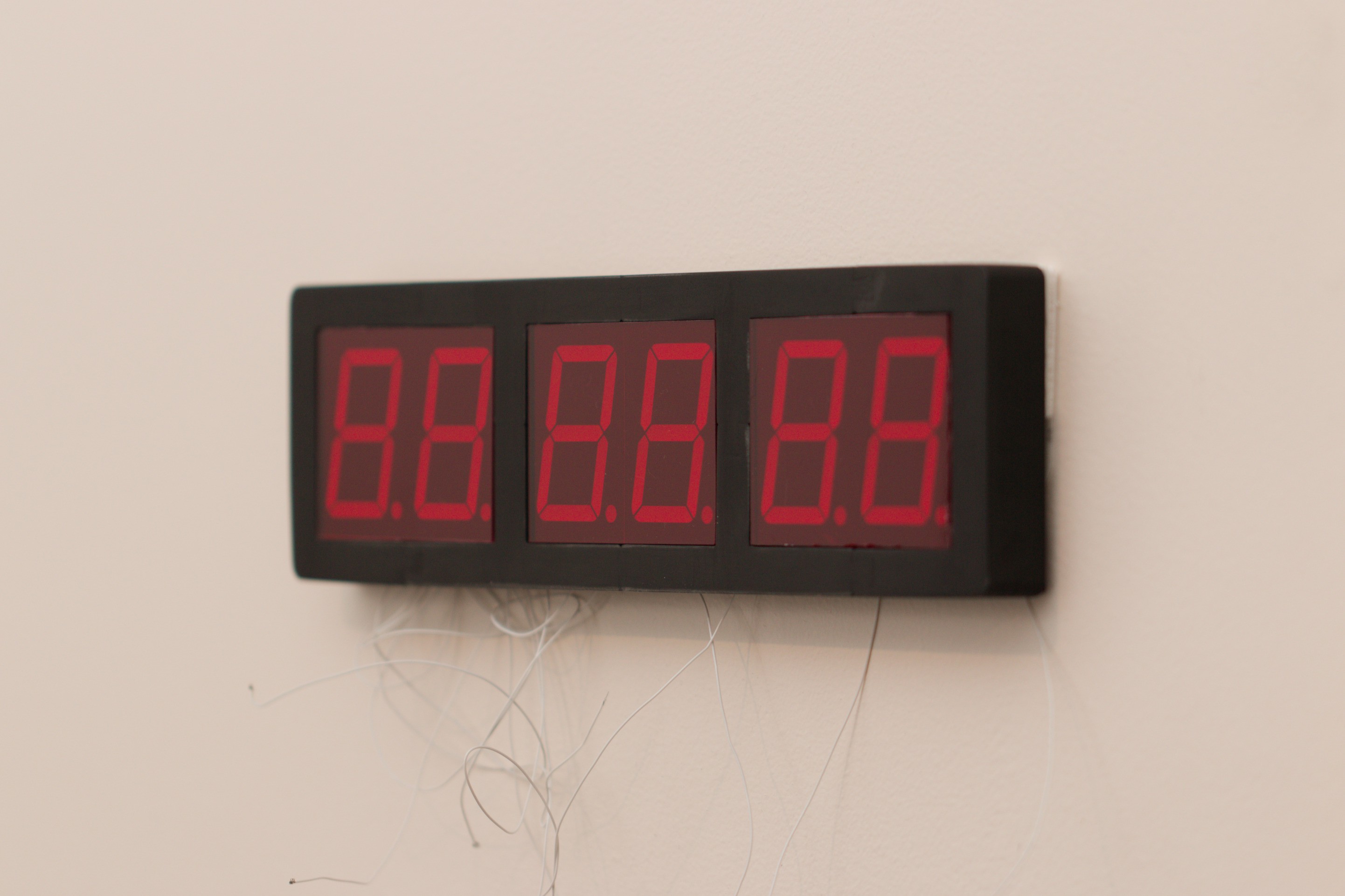
I didn't like the look with a single piece of acrylic across the front, so I broke that filter into smaller pieces and recessed them:


 Pierre-Loup M.
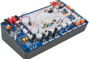
 Just Me NL
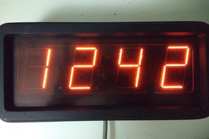
 Ken Yap
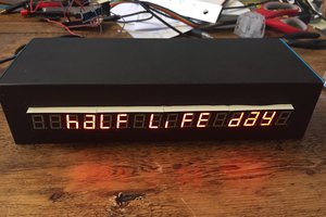
 Mark VandeWettering
Absolutely flawless execution! I'd give more than +1 if I could!