 Stephen Holdaway
As winter approaches here in the southern hemisphere, the wire-wrapping from the original build of this display is proving to be be a bit unreliable. Without proper wire-wrap pins and the right tool, there's just not enough force to stop connections coming loose. The effectiveness of percussive maintenance has been dwindling, so it's time to for some upgrades.
Better display connections
I thought about simply adding solder to the wire-wrap joints to make them more robust, but the mess of overlapping wires meant I was likely to melt some insulation and short pins out. Instead I figured I'd completely replace the point-to-point wiring with some PCBs to make it tidier and stronger.
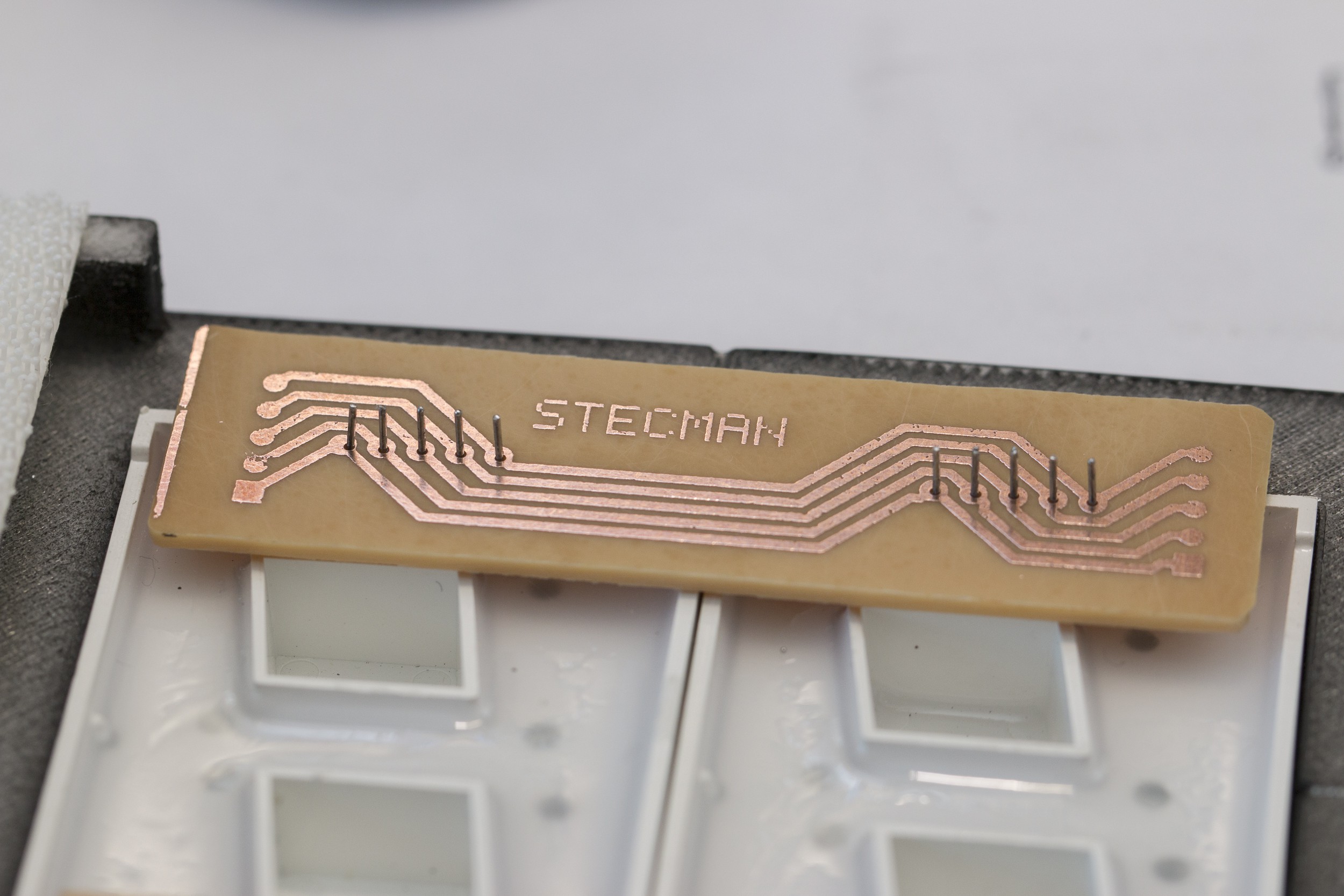
After a few iterations of layout, I ended up with two small boards to attach to each pair of digits that connect all of the segments:

I needed this fixed over the weekend, so the layout was designed for etching my own PCBs instead of ordering them. Ideally this would've been one long board to connect all digits, but the equipment I have makes it impractical to make a board larger than about 100mm square.
These are fiddly to make, but they turned out ok:

Once constructed, the 6 boards were soldered into place and wired together with 0.5mm (22 AWG) solid copper wire. 16 wires was far more manageable than the 40 point-to-point connections when I wire-wrapped these originally:

Once the driver was wired back in, I was pleased to find I hadn't made any mistakes or shorted or broken anything. The original build had the digits wired backwards which I'd neglected to fix in hardware at the time and was managing in my local copy of the code:

With sturdy new connections, the clock should hopefully be maintenance-free for quite some time.
As a finishing touch I added a 50uF electrolytic capacitor to the board to stop the ceramic caps whining when the display is being driven at a high brightness. This wasn't audible originally and I'm not sure why it's occurring after 3 months of use, but the extra cap has completely silenced it.
Firmware improvements
Over the last couple of months we've seen an unexpected timezone increment a number of times - usually by one or two steps, and usually overnight or when the house was dark in the evening.
The most likely suspect was the shared ADC reading for the light sensor and timezone change button that only required a single sample below a set threshold to increment the timezone. I've changed this to require 5 readings 100ms apart before the timezone will be incremented (fix), putting the existing 500ms delay to use.
The uncommanded timezone increments also revealed a bug where a negative value for hours wasn't being wrapped (fix). This resulted in some mild entertainment:
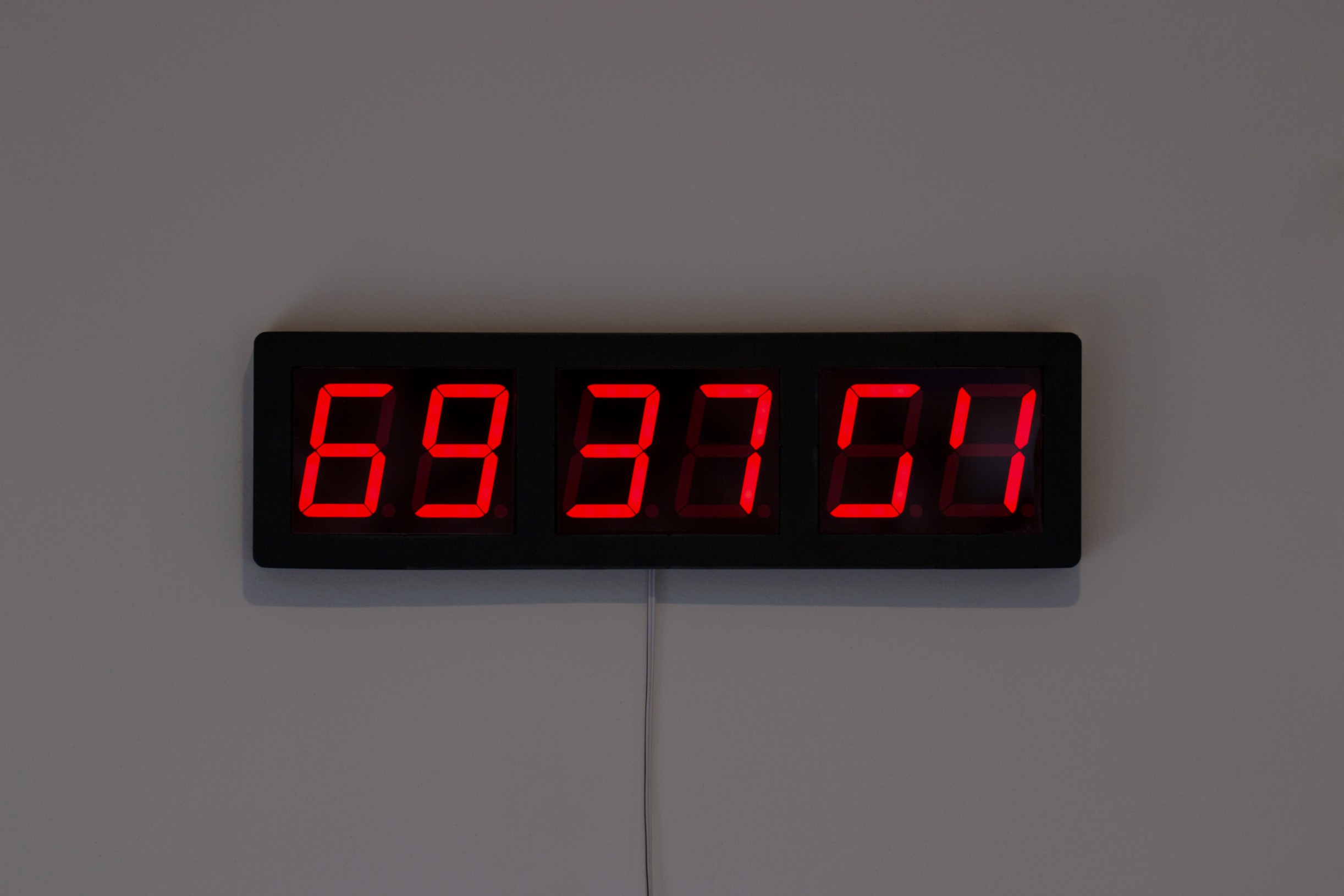
The fun thing here is that the hour is correct in the one's column when the timezone is set to -12 due to the way the math works out:
# Unsigned addition of -12 offset to UTC hour "09"
9 + -12 = 253

# Reduced by 24 as the value is greater than 23
# This makes the ones column match the UTC hour
253 - 24 = 229
The "6" comes from the MAX7219's interpretation of the tens value:
# The number of tens is calculated
229 / 10 = 22

# Displayed as "6" because the MAX7219 ignores the high nibble
22 & 0x0F = 6
I made these fixes a few weeks ago, but I'd been putting off updating the firmware for this as it's a bit of a pig to program: the footprint for the programming header is the wrong pitch, so instead of using a pogo-pin jig as intended, each connection has to be made manually with test clips:
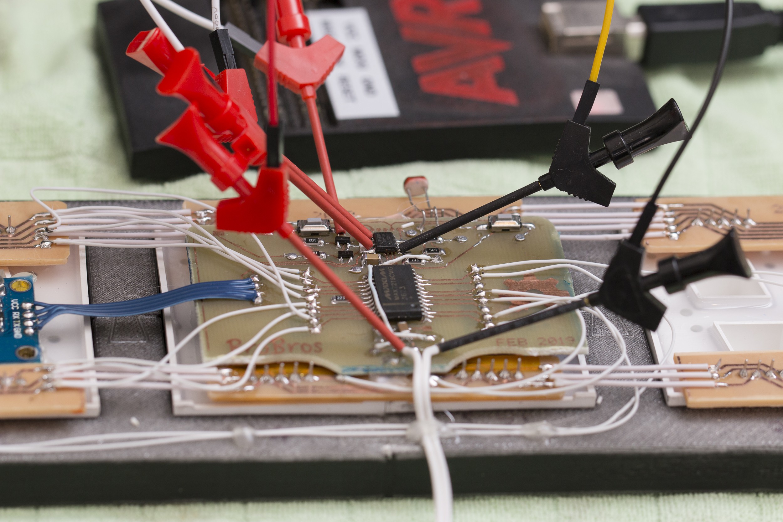
The digit order needed to be corrected before the display could be used again, giving a chance to push these fixes at the same time. As a bonus, I no longer have to maintain a digit-reversed version of the code while keeping the code in the correct wiring on GitHub!
Discussions
Become a Hackaday.io Member
Create an account to leave a comment. Already have an account? Log In.