Close
0%
0%

USB-C-PD Soldering Pen for Weller RT Tips

Small and powerfull controlling unit powerd from USB-C-PD

Public Chat
Similar projects worth following
This is my project to build a controller unit for the Weller RT-tips.
The intention for this project was to built a cheaper and even more compact
controlling unit for one of the best soldering tips for small and medium sized soldering joints. It aims to professionals who not want to pay from around 700€ for a big controlling unit but also like the professional feel and results of these tips. Another big benefit is the high variety of different tips.

By the time this project wasn't cheaper than buying a finishend Weller station, but I still have lots of fun working on this project. However, I have a soldering pen which fulfill all my needs!
Soon everybody can have one because I will share the production files.

I'm very glad that my project made it into the top 20!

Enjoy looking around on my project page and feel free to like and leave comment!
Ideas for improvements are welcome :)

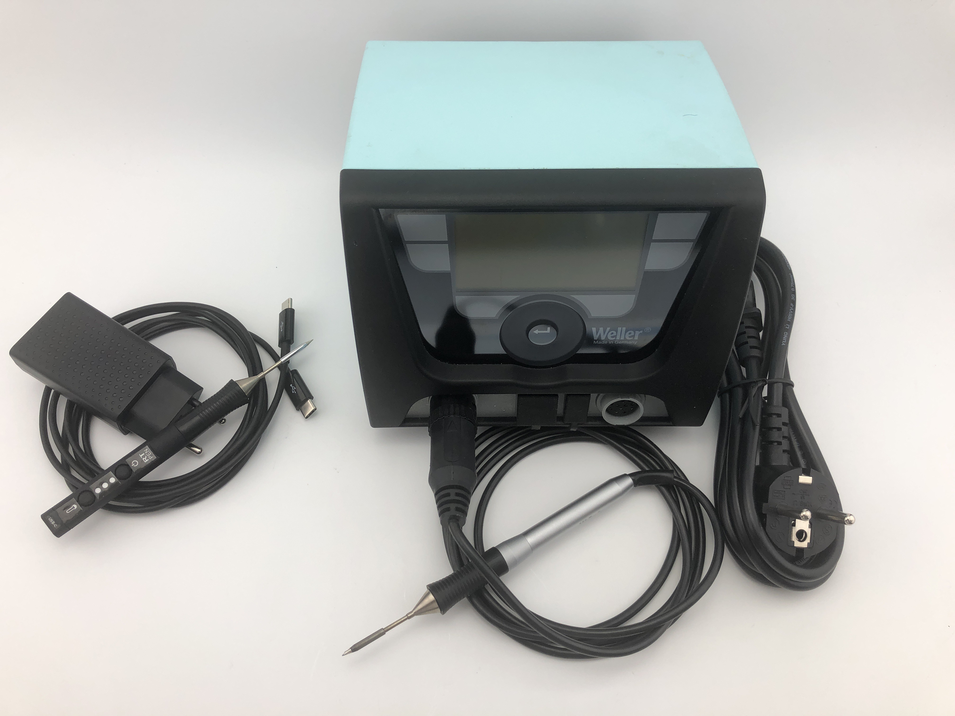
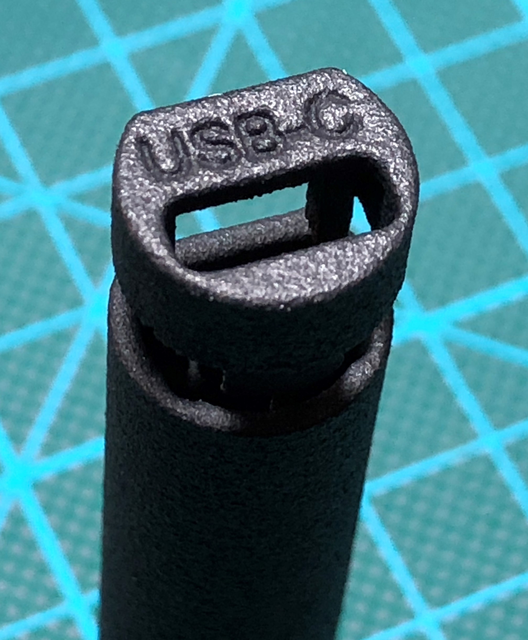
I have used the PD 3.0 with 9V/3A for supply. It can be powered from an USB-PD power supply (even suitable laptop USB-C power supplies) or with an PD-Power bank for soldering on the go.
The heat up time from 25°C to 350°C is around 6s. Auto-standby temperature is around 180°C, by picking up from the rest around 3s are needed to reheat.

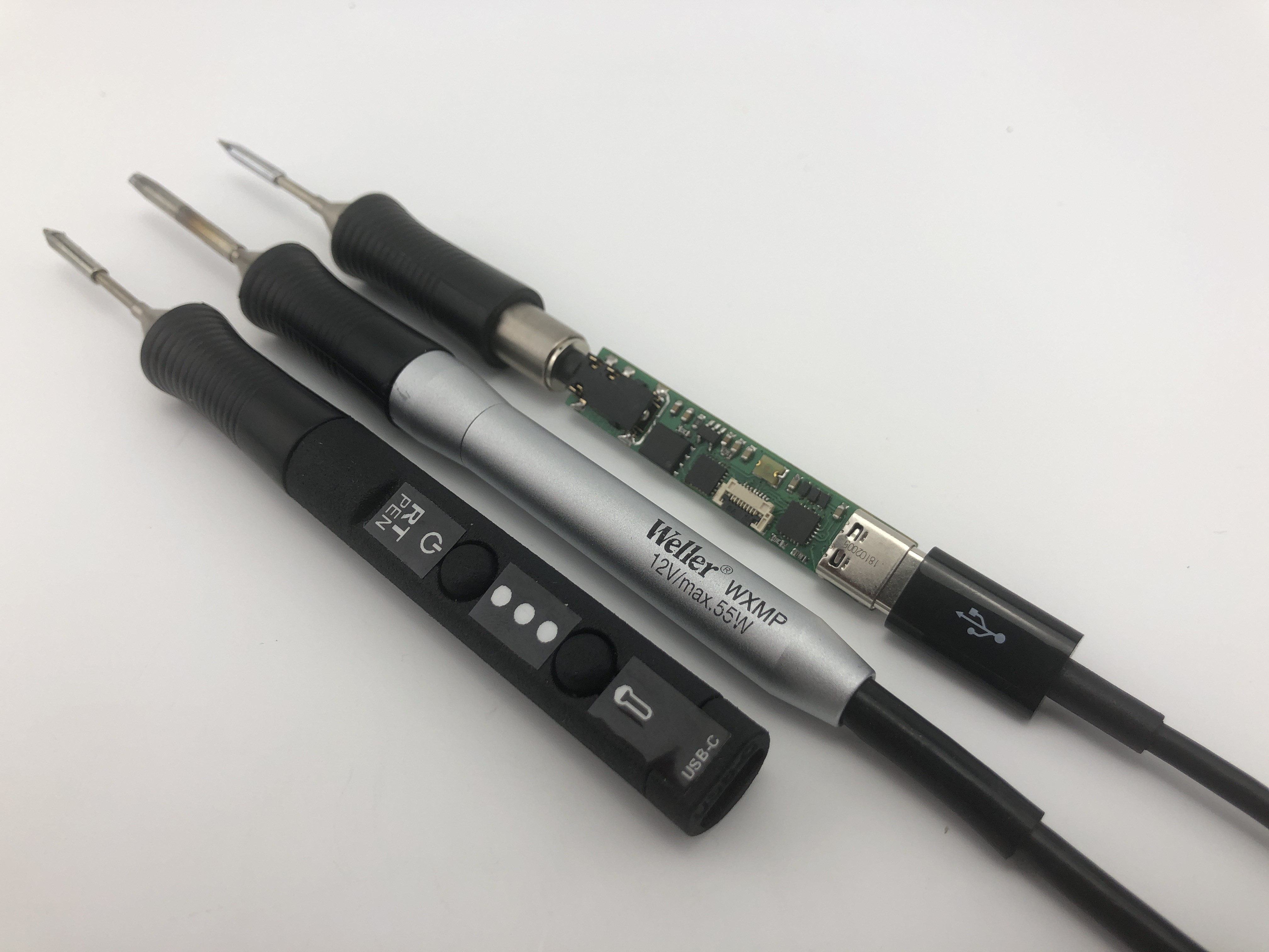
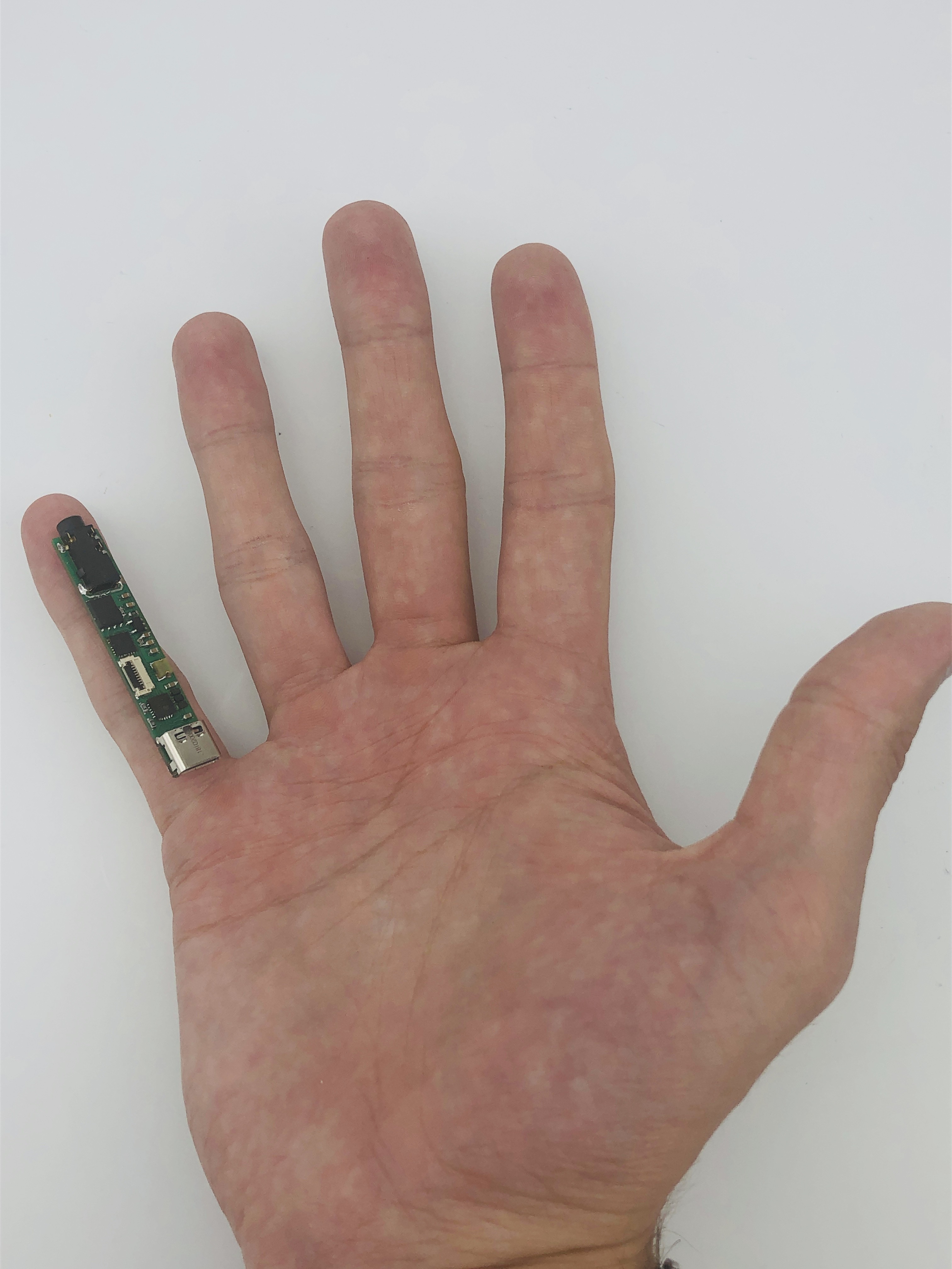
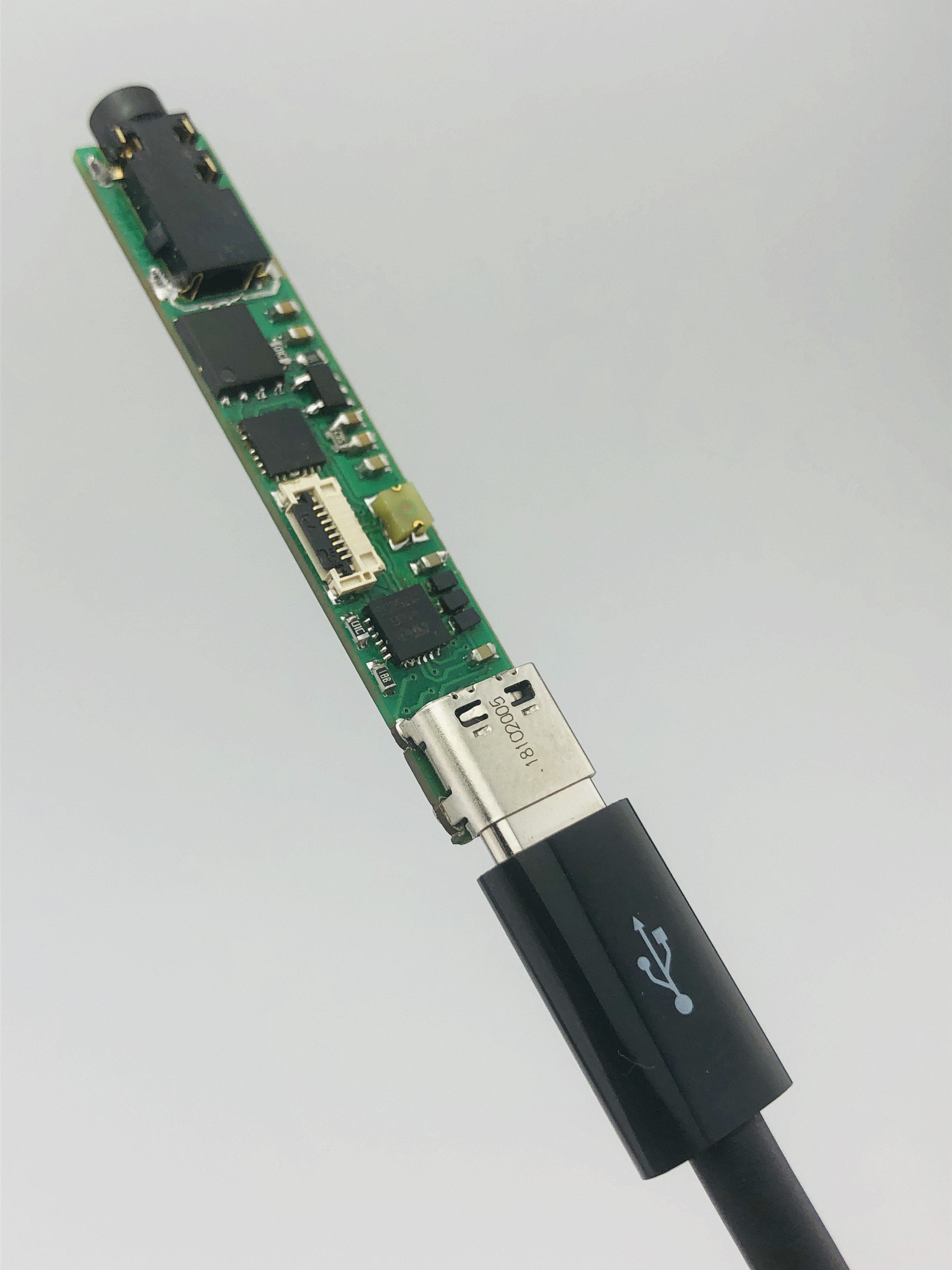
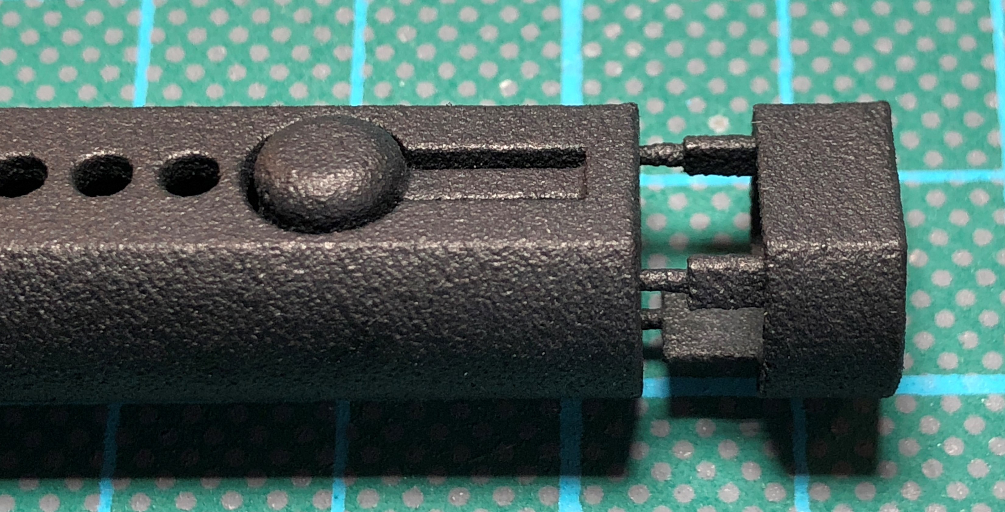
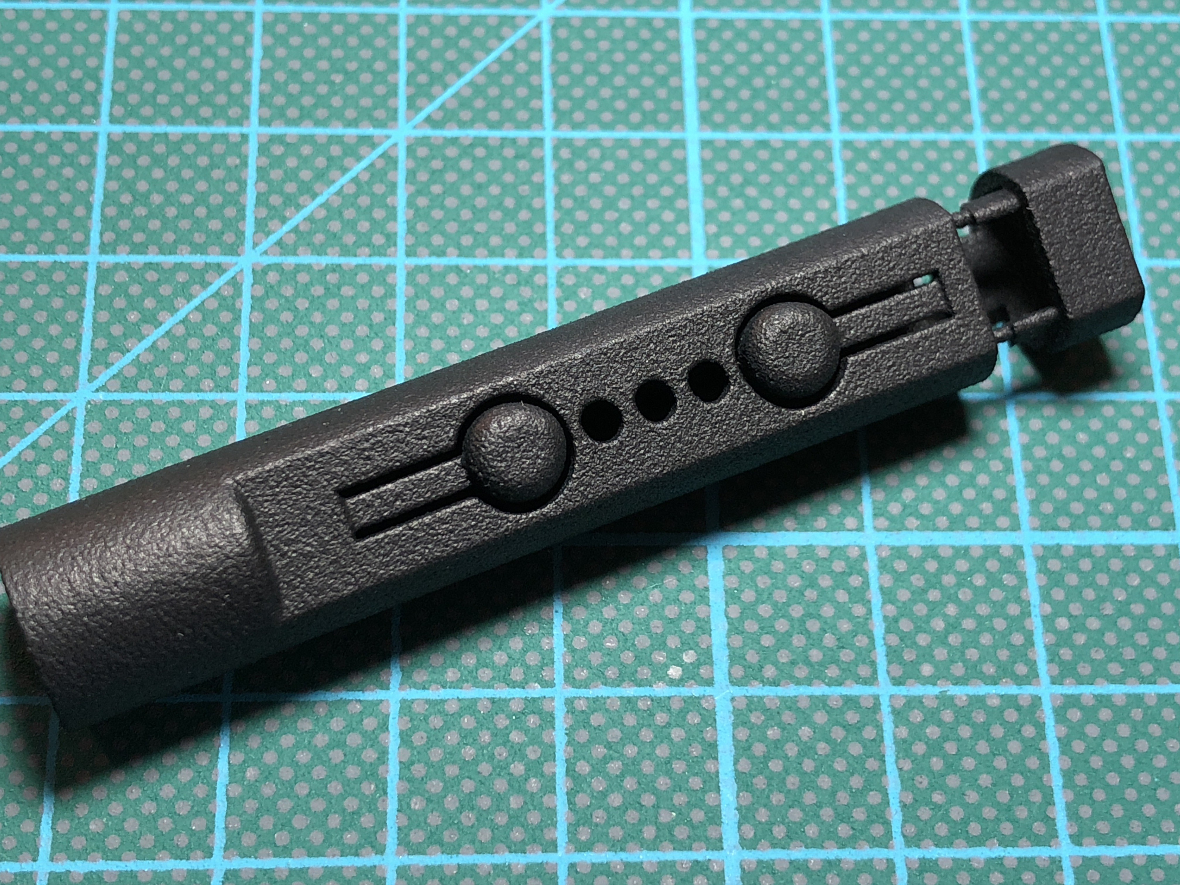
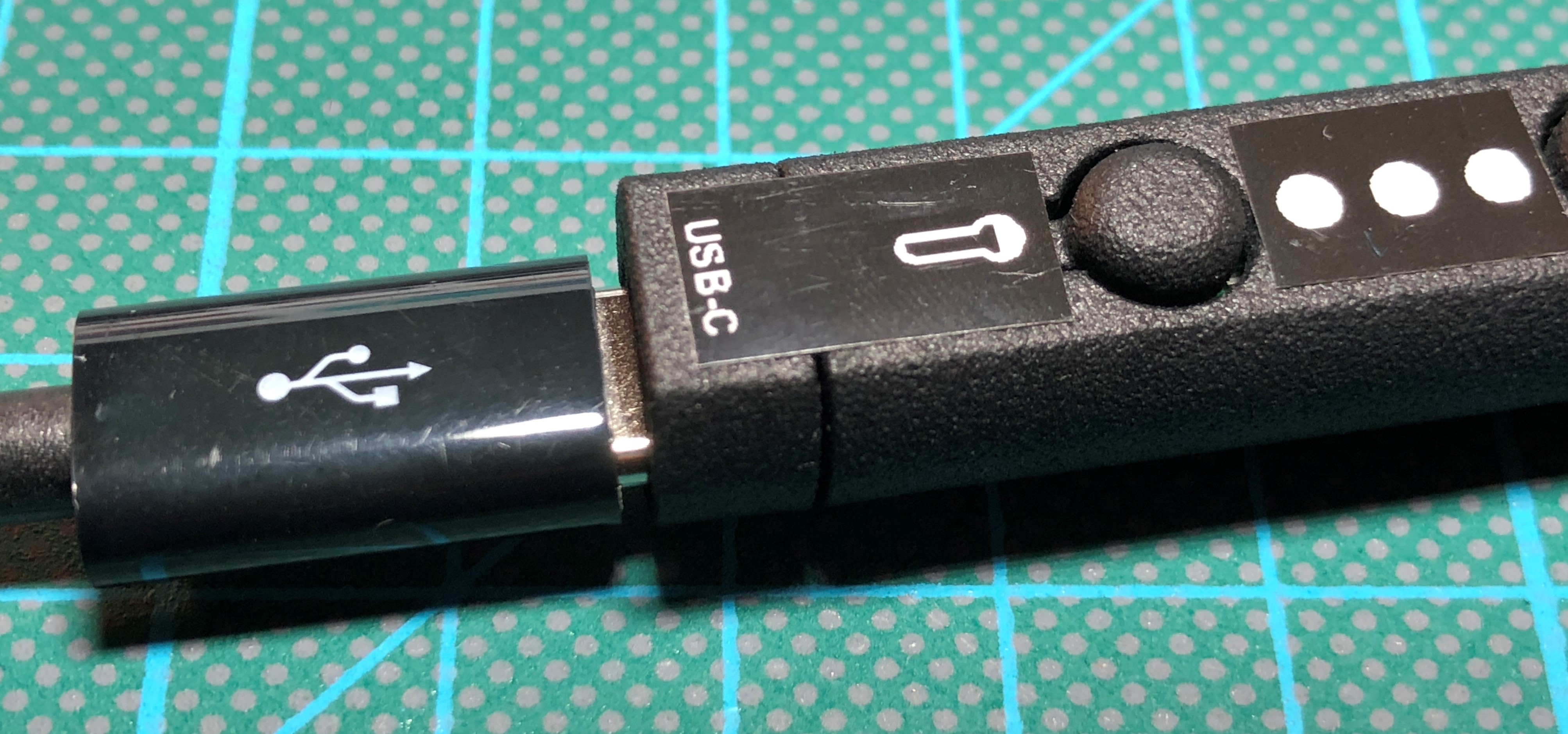
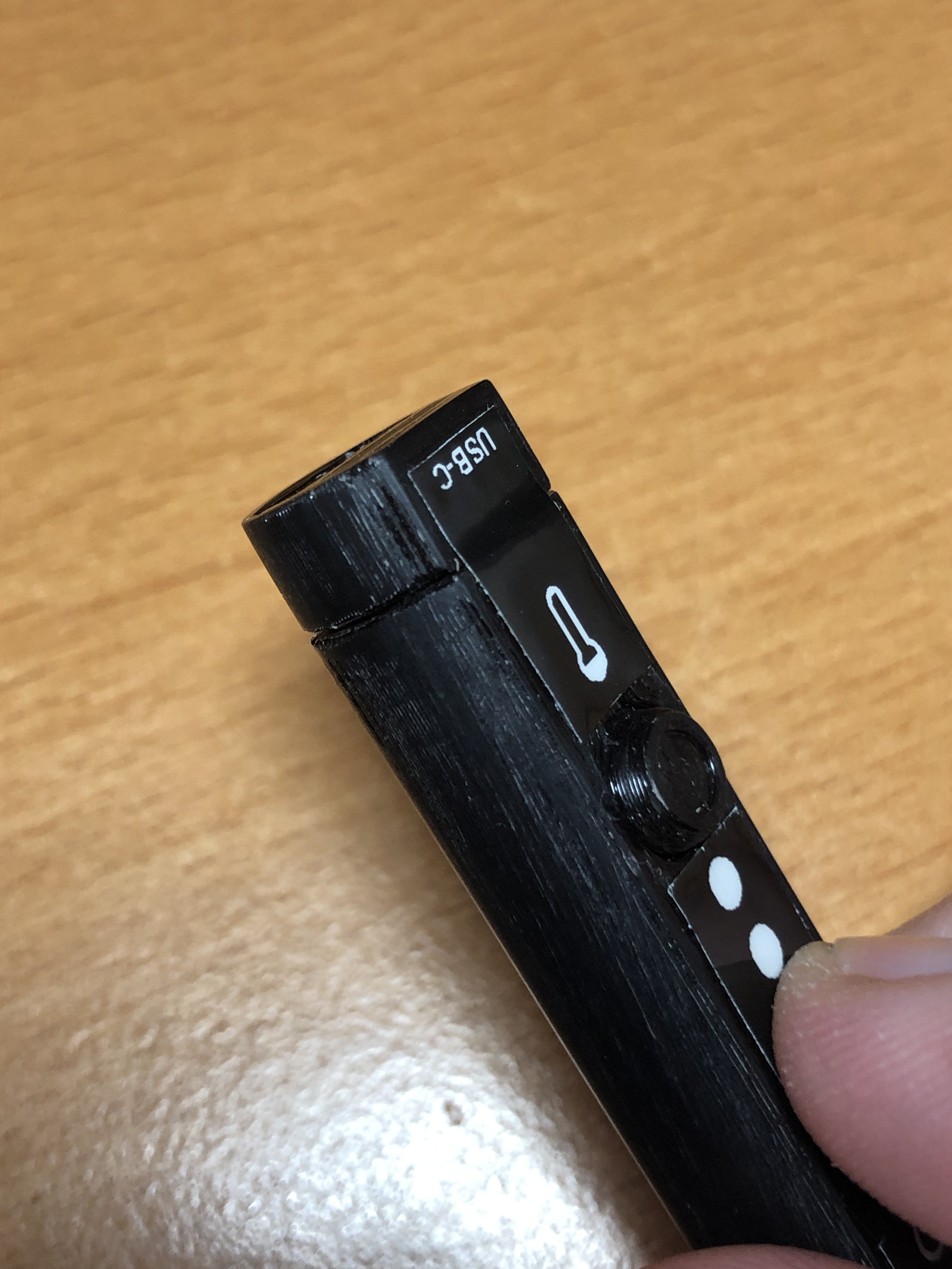
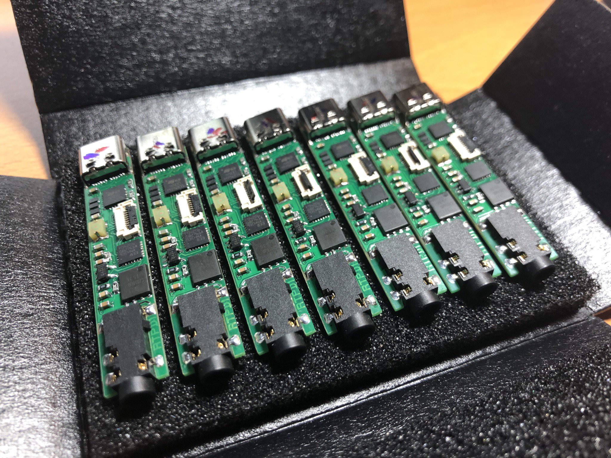
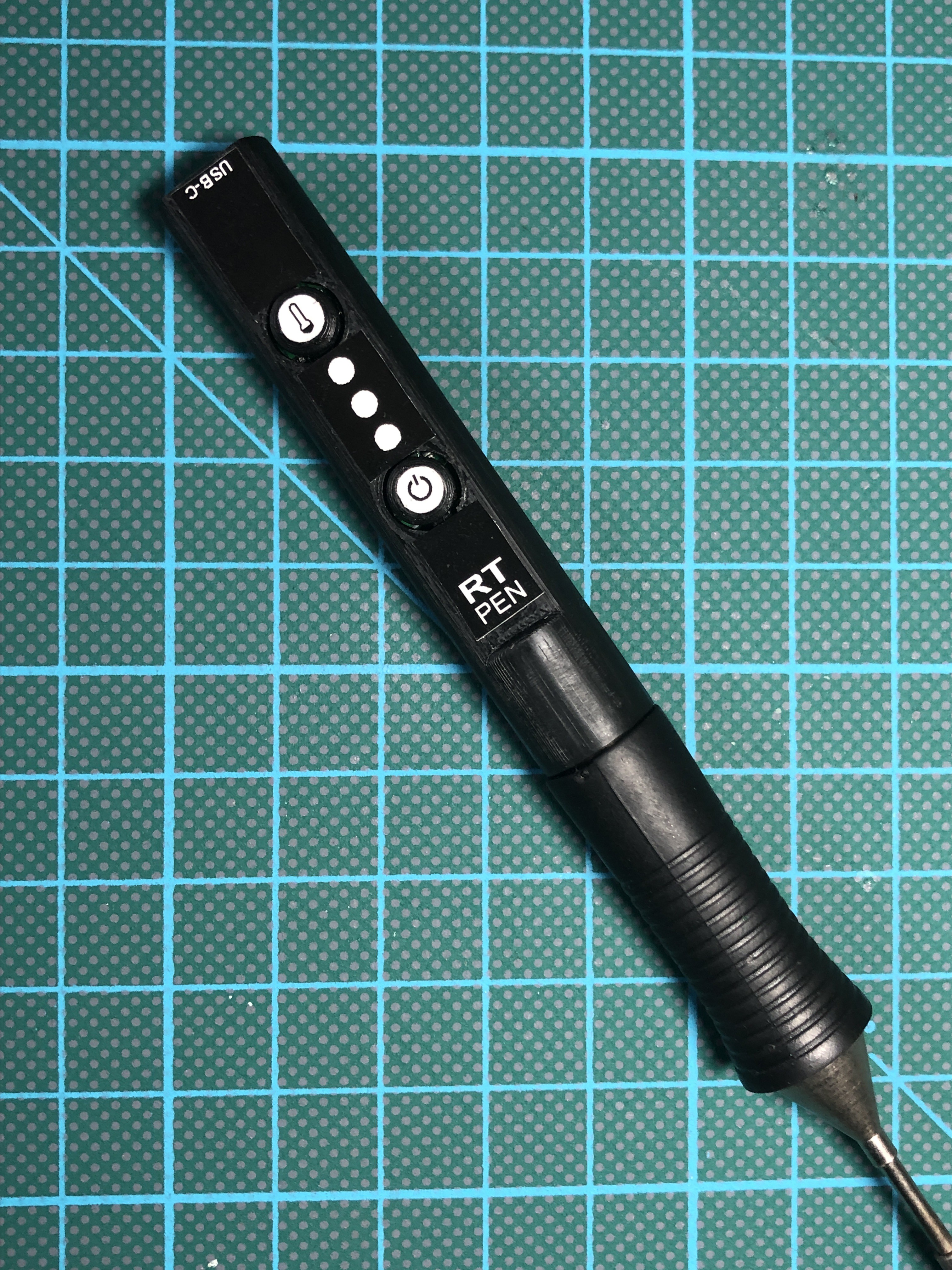
The main goal by the designing the PCB, Enclosure and UI was not to exceed the diameter of rubber grip to keep it as small, handy and portable as possible.

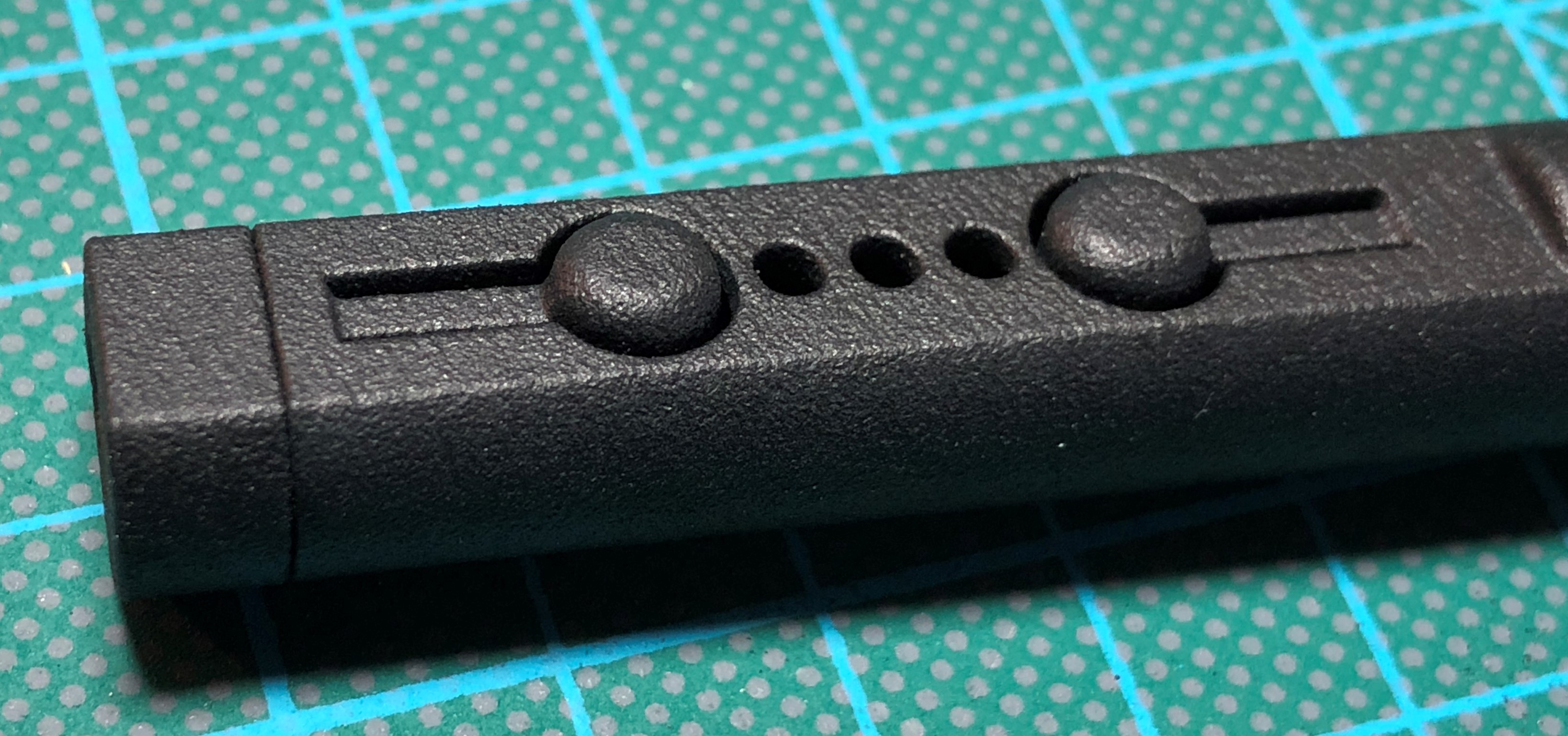
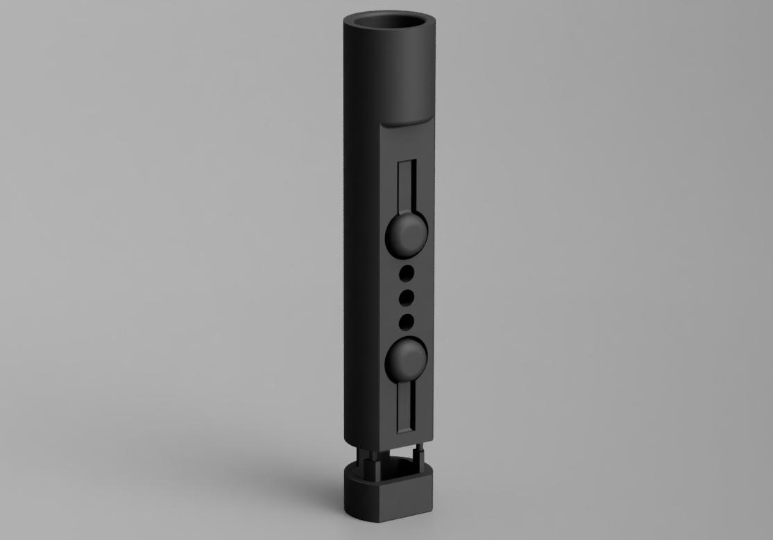
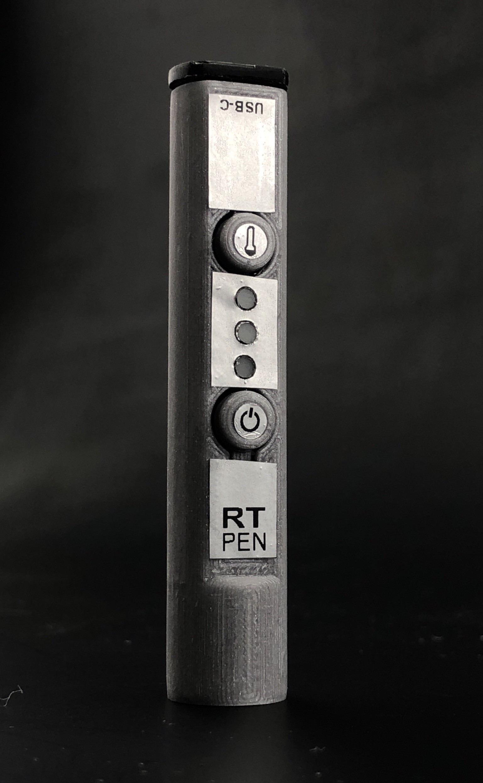
The user-interface consist tree LED's and two buttons. The LED's indicate which temperature profile is active (Low, Mid or High) as well as the operating modes (user-standby, auto-standby, auto-off, warm-up and overheat). 

Its UI is simple! - If any LED blinks, the Soldering Pen is not ready or at the desired temperature range. Steady light than means that the pen is ready.

I have chosen the simple 3-LED-Display because there is no need to set or know the temperature in 1°C steps. There are three basic groups of soldering types:

- Very sensitive components(e.g. temperature sensors)

- Regular sensitive components and Wires (e.g. Resistors, Capacitors, most types of IC's)

- Not sensitive parts (e.g. large copper areas)

Based on this knowledge I implemented the three profiles.

One button controls the user-standby mode the other changes the temperature profiles.
The pen fits perfectly in the original Weller safety rest WDH 51.

When it comes to a regular transportation (eg. in tool cases) weight ist very important. The soldering pen itself wights around 9 grams, with tip (RT1) 19 grams. Complete set with soldering pen, tip, cable and power supply (DA45C) is just around 150 grams! Less than a modern smartphone.

Here are the video demonstrations:

Adobe Portable Document Format - 799.84 kB - 09/30/2019 at 19:44

Preview
Download

RTPD1-SW_v3.hex

Software for the Soldering Pen

hex - 34.13 kB - 09/30/2019 at 09:56

Download

plain - 245.00 bytes - 09/30/2019 at 09:49

Download

Development and Prototype history.pdf

This document shows every prototype stage in the past with its requirements.

Adobe Portable Document Format - 1.17 MB - 09/30/2019 at 08:35

Preview
Download

Portable Network Graphics (PNG) - 17.71 kB - 09/30/2019 at 08:28

Preview
Download

View all 13 files

  • 1 × STM32F042G6U6 MCU
  • 1 × DMC1016UPD-13 Dual Mosfet
  • 1 × LM3480IM3-3.3/NOPB 3V3 regulator
  • 1 × F721A108MMCAQ2 1000µF Cap
  • 1 × STUSB4500QTR USB Controller

View all 6 components

  • New photos and size comparison

    Thomas Leputsch09/20/2019 at 17:19 0 comments

    I've done a side by side photo of the RT Pen and the original Weller.

    When about the half wattage is enough, much table-space and cash can be saved with RT Pen. The RT Pen includes every feature for hobbyist usage. 

    I've tested the the RT Pen with the new GaNFast power supply from AUKEY (PA-Y21) with 30 Watts. Worked fine, and is even smaller and more lightweight than the used from ARTSYN power supply. 

    Here are some photos of the comparison:

  • New housing just arrived

    Thomas Leputsch09/17/2019 at 15:11 0 comments

    The order of the 3D-Printed cases just arrived. I'm very impressed by the precision and surface.

    The three joints from the cap to the main body printed as expected. To remove them just cut them near the cap than  do break/cut the remaining joints off with a small flat screwdriver. Very easy and time-saving when doing larger batches.

    The parts are made of Nylon and have a nice semigloss black finish with an rough surface which has a very good grip and feel. No fingerprints are visible on the surface. 

    For now I used the not so nice cut old stickers I had here but im currently working on new one. 

    The sticker at the USB-C side also secures the -already tight in place- cap from falling off.

    Here are some photos:

  • Composition of Parts

    Thomas Leputsch09/13/2019 at 13:39 0 comments

    With the PCB already inserted, the following animation shows how the remaining parts are put together.

  • Professional MJF 3D-Print

    Thomas Leputsch09/11/2019 at 10:56 0 comments

    New, slightly improved design is just put into production in a professional 3D-Printing house.

    I've chosen Nylon PA12 with an 80µm layer height in semigloss black.

    The prize @100 pcs. comes down to a few Euros.

    This is a render of the current CAD model. Optimized for one-print-job. 

  • Improved cap design

    Thomas Leputsch05/04/2019 at 15:48 0 comments

    With the new design the cap can be hold in place by the top-sticker or additionally with a wraparound-sticker. Fits perfectly now with the USB-C.


  • Just soldered some boards

    Thomas Leputsch05/03/2019 at 17:04 0 comments

    All new PCB’s are fine. Just a little SW adjustment due to a new OPA.

  • 3D-Printed transport case

    Thomas Leputsch04/04/2019 at 20:05 0 comments

  • Silver edition ;-)

    Thomas Leputsch03/01/2019 at 18:49 0 comments

  • New 3D Print

    Thomas Leputsch02/24/2019 at 15:08 0 comments

    This is the current version of the housing, now with labels on the buttons. The button size is also increased for better pressing feedback.

    Outer diameter of the housing now is 12.5mm. Nearly the same as the rubber grip on the RT Tip.

  • USB Virtual COM-Port and housing

    Thomas Leputsch02/17/2019 at 15:40 0 comments

    Just finished programming the USB connection directly from/to the STM32. Next step will be to implement an emulated EEPROM because there in no dedicated data EEPROM on the used STM32.

    New housing design is also finished.

View all 11 project logs

Enjoy this project?

Share

Discussions

alightmotionmodapkoffical wrote 07/31/2023 at 07:03 point

How are you powering the top? Square wave, sine wave switched at crossing, something more distinctive?  I want to strive something like this, and I need to layout it myself, but I need to ensure to do it proper. Seems like you are doing this right.

you can see here https://alightmotionmodapk.org/alight-motion-pro-apk/

  Are you sure? yes | no

lajoidcnds wrote 06/19/2023 at 06:06 point

Hye, you are doing a great job, and I want to interlink this with my blog webpage. You can find more information about this:) https://boardsriding.com/tips-and-guide/

  Are you sure? yes | no

Insta_Jun wrote 01/31/2021 at 19:37 point

you konw, the fun thing in this project is that, In order to build a soldering pen, you must firstly buy a solding pen for PCB soldering. LOL
BTW. i have a few questions to the schematic.

  1. why don’t we place a filter capacitor near the voltage supply pin of op amp, MCU and PD?
  2. what is the purpose of the tanatal capacitor? is a 1 uF capacitor not enough?

Thanks!

  Are you sure? yes | no

Matt M wrote 01/31/2021 at 17:45 point

Hi, can you share the tip characterization data with us to use as a baseline? I'd imagine all the tips are slighty different and can vary but it would be helpful to see what relation you had with yours.

Also, what frequency are you using on the PWM? Probably down in the Hz right? 10 or so?

  Are you sure? yes | no

scheuss wrote 05/14/2020 at 07:11 point

Hi, thank you for that awesome project, we made two and they work very well. However, we would like to make some customization in the firmware. Would it be possible to upload the source code?
Thanks

  Are you sure? yes | no

coldfire wrote 01/19/2020 at 16:53 point

do u have an alternate for F721A108MMCAQ2, i cant find this item anywhere in stock in the uk

  Are you sure? yes | no

Thomas Leputsch wrote 01/20/2020 at 07:02 point

Hi, from the electronics side it depends on the power supply. In some cases it may work without. From the mechanics side, it is used to center the pcb if you plan to use my case design. 

Have you checked stock at mouser? 

  Are you sure? yes | no

coldfire wrote 01/20/2020 at 10:34 point

yep tried mouser, they are out of stock with 46 week lead time

  Are you sure? yes | no

3gfisch wrote 01/10/2020 at 00:33 point

Hi again :) I tested some soldering with an old Weller RT “Messer” tip and it worked, then I ordered new tips and tested the RTM 008 S tip and first it worked but after few minutes soldering it stopped working, form what I measured the heat element seams broken now it has a high resistance ~26 Ohm instead of ~1,7 Ohm for the old still working one. I fear to destroy also the second new tip I have, does anyone have any idea how this could happen? Max USB C PD Profile configured is 9V 3A.. thanks

  Are you sure? yes | no

Thomas Leputsch wrote 01/10/2020 at 06:04 point

Hi, nice made PCB. Black looks good :-) 

Im sorry that this happened... do you noticed a red glowing tip before it died? Maybe a slight change of the thermocouple caused a over regulation? Hard to say due to I only worked with the ‘old’ RT tips. 

As for the software, I think it’s more easier to create a new one because it’s quite simple. If you need help then, I can help you. 

Best regards,

Thomas 

  Are you sure? yes | no

3gfisch wrote 01/11/2020 at 10:36 point

no I dint noticed red glowing, i think it got broke while solder so suddenly it got cold without overshooting 🤔 maybe it was a bad tip..

Ok thanks I will try it, first I have to find an IDE, compiler and so on, im new to ARM ^^ only AVR used so far.

For the modified PCB with I2C connection, would you share the eagle files or whatever program was used? Thanks very much 😉

  Are you sure? yes | no

vlk wrote 01/20/2020 at 16:32 point

Hello, what you use for tip cleaning ? it is wet sponge or metallic brass sponge ?

  Are you sure? yes | no

3gfisch wrote 01/08/2020 at 20:54 point

We have builded two PCBs and want make a few more for our DIY friends and it looks fine so far, it would be great if you could also provide the source code. if we like to change the control loop and due to availability we have other vibration sensors which we would need to adjust the SW cause it’s going always to standby..

What we also discovered, we can’t use it with a wider current range, for example 9V 2A (basic iPad power supply) cause the MCU can’t know which profile the PD chip has negotiated and will kill the 2A limit with the 3A the MCU thinks it got. So it would be awesome if you could also publish the modifiable layout / schematics, that we can add I2C communication between the chips before building the final versions.

Thanks very much :)

Pic of the black PCB :)  https://pasteboard.co/IHhIBNl.jpg

  Are you sure? yes | no

Gregor wrote 01/07/2020 at 15:32 point

I would gladly buy this PCB/complete product, are you planning to offer it for sale anywhere?

  Are you sure? yes | no

Thomas Leputsch wrote 01/10/2020 at 06:07 point

Thanks for your positive feedback. No sorry, by the time I will not sell finished units. 

  Are you sure? yes | no

Andreas Kahler wrote 01/07/2020 at 13:52 point

Awesome project, Thomas!

Thinking about building one for myself. Is the PCB 1.6mm thick or has it a non-standard thickness to fit into the case?

  Are you sure? yes | no

Thomas Leputsch wrote 01/07/2020 at 14:23 point

Hi Andreas, 

Thanks for your feedback 😀

Good idea to build some! 

1 mm PCB thickness should be used, as you can see in the partlist.

Best regards, 

Thomas

  Are you sure? yes | no

Andreas Kahler wrote 01/07/2020 at 15:14 point

Ah, missed that. Thx!

  Are you sure? yes | no

John Loeffler wrote 10/12/2019 at 21:38 point

I was looking at your vibrations sensor.  It seems to be a large cost of your parts list $4 where your total is $19.  Since you have a MCU you could use those cheap $0.30 Accelerometers.  They have a low power mode and you can have them trigger an interrupt to any pin when there thresholds are exceeded.

  Are you sure? yes | no

Thomas Leputsch wrote 10/12/2019 at 22:26 point

Hi John, yes its a quite expensive part in the part list and also with limited availability. I chose them due to its simple implementation and no need of extra components. Just one track to the MCU. In a next version I will try to remove the PD-Controller, than is enough space for an accelerometer ;-)

  Are you sure? yes | no

TG-Techie wrote 10/09/2019 at 04:09 point

Great Job!

  Are you sure? yes | no

Thomas Leputsch wrote 10/09/2019 at 04:19 point

Thanks :-)

  Are you sure? yes | no

Code and Solder wrote 10/07/2019 at 19:43 point

Are you planning to sell those (or at least assembled PCBs) any time soon? I'd love to have one and ordering assembly and parts @qty1 is not that practical.

  Are you sure? yes | no

Thomas Leputsch wrote 10/08/2019 at 19:10 point

Hi, thanks for your interest. 

I will not sell it in the near Future due to its a quite big step from a prototype to production. Depending on the interest in the next weeks I will reconsider if it’s worth. I’ll keep your comment in mind and reply if something changes. 

  Are you sure? yes | no

flokreiner wrote 09/24/2019 at 18:10 point

Are you going to upload the code? Id like to try building one myself. 

  Are you sure? yes | no

Thomas Leputsch wrote 09/25/2019 at 08:11 point

Sure, I will upload it the next days. Also an manual how to program. I hope you have good soldering skills ;-) 

  Are you sure? yes | no

opticron wrote 09/23/2019 at 13:03 point

You mention that you tested with 9V/3A PD. Does it work with other voltage profiles as well? I'd expect other 9V PD profiles to work as well, but what about 12V? I only ask because some USB-PD supples have an odd selection of profiles they support and will occasionally leave out commonly supported ones.

  Are you sure? yes | no

Thomas Leputsch wrote 09/23/2019 at 16:18 point

Hi, sure it works with higher current settings too. The driver is set to request the maximal current. 12V is theoretically possible but most of the supplies can’t handle the peak at the beginn of each pulse. Original weller works with 12V and 55W quite high for this size and not really necessary in most cases. Also 9V/3A is a very popular profile on the most power suppliers.

  Are you sure? yes | no

3gfisch wrote 09/12/2019 at 18:08 point

Are the schematics and layout available? Really cool project, we had the the same idea but not really startet it..

  Are you sure? yes | no

Thomas Leputsch wrote 09/12/2019 at 19:11 point

Hi, Thanks! Within the next Week I will publish schematic and a detailed partlist. 

  Are you sure? yes | no

Thomas Leputsch wrote 09/20/2019 at 17:45 point

As promised, from today you can find the schematics under the Files tab. Enjoy building your own unit! If you have questions feel free to ask :-) 

  Are you sure? yes | no

3gfisch wrote 11/18/2019 at 17:09 point

we are currently building your PCB and it looks fine so far, we still need to flash it but could you also provide the source code if we like to change the control loop? Thanks very much :)

Pic of pcb:

https://pasteboard.co/IHhIBNl.jpg

  Are you sure? yes | no

John Loeffler wrote 09/11/2019 at 23:15 point

I know we are competitors for the Hackaday Prize but I do like your project.  I ran a 3d printing lab for a while you may want to look into soothing the parts wit a solvent.  I found that

Smooth-On XTC-3D worked fantastic. 2-3 smooth / sand gives it a nice finished look.

(https://www.amazon.com/Smooth-XTC-3D-Performance-Print-Coating/dp/B00PFXK4JY)

  Are you sure? yes | no

Thomas Leputsch wrote 09/12/2019 at 07:18 point

Thanks a lot man! I really appreciate that :-)

It seems that this is some kind of epoxy with very low viscosity. I already thought about something like that but didn’t tried it yet because the small details and gaps at the actuators may get lost or clogged and the of course working time and a bad reproduction are factors when thinking about more than a few pieces.

I hope that the ordered enclosure with a stated ‘semigloss’ coating looks quite good. 

I like your project too especially the stunning renderings and animations. Nice work John and good luck for the Hackaday Price.

  Are you sure? yes | no

Tinkerhaus wrote 09/11/2019 at 17:20 point

Please kickstart this - take my money! 

Great job. Thomas

  Are you sure? yes | no

Thomas Leputsch wrote 09/11/2019 at 18:28 point

Thanks for your positive feedback!

The Hackaday Price could be like a kickstart to finance EMC and safety testings, moulds, as well as the first Batch of Units. :-)

  Are you sure? yes | no

[deleted]

[this comment has been deleted]

Thomas Leputsch wrote 05/02/2019 at 07:59 point

Hi, thanks for your offer! By the time you can support me by liking my Project due to ongoing Hackaday Price 2019.

  Are you sure? yes | no

Tom Kelley wrote 04/22/2019 at 04:07 point

How are you powering the tip? Square wave, sine wave switched at crossing, something more exotic?  I want to try something like this, and I want to design it myself, but I want to make sure to do it right. Seems like you're doing this right. Good project, BTW. :)

  Are you sure? yes | no

Thomas Leputsch wrote 04/22/2019 at 09:11 point

Hi Tom, I‘m glad that you like it :-) 

I used a PWM, but it’s important that you not read the thermocouple voltage while the heater is on. Watch your tip carefully when testing because it takes seconds to  damage them irreparable ;-) 

Regards, 

Thomas 

  Are you sure? yes | no

Tom Kelley wrote 04/22/2019 at 14:41 point

You're the man, man. 

  Are you sure? yes | no

Similar Projects

Does this project spark your interest?

Become a member to follow this project and never miss any updates