 SHAOS
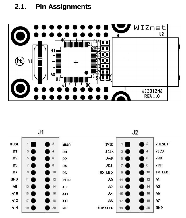
SHAOSAs I wrote in details I plan to use WizNET module WIZ812MJ (WIZ811MJ can also be used, but it doesn't have extra LEDs outputs and it's not currently available, at least on Digikey):
On-board Ethernet chip W5100 has 3 modes in which it may work:
- Direct Bus Interface mode - all 15 address lines (with 8 data lines and a few control lines) are used to address internal 32KB memory directly;
- Indirect Bus Interface mode - only 2 address lines (and all 8 data lines plus a few control lines) are used to access 4 registers that address internal 32KB memory (it's also possible to set autoincrement for address during reading or writing);
- Serial Peripheral Interface (SPI) mode - regular SPI inputs/outpus (/SS, SCLK, MOSI, MISO) are used in this mode (and all other address/data/control lines are ignored).
So we are interested in Inderect Bus Interface mode, because we have only 3 address lines available (and it's IO space, not MEM space) - to control WinNET module we will use 2 (A0 and A1) and 3rd one can be used to access ROM that will be soldered separately on the board to store MAC address and may be some other things for user. So, for user it will look like this:
3F8h - register MR of W5100 (indirect mode flag and auto-increment flag)
3F9h - register IDM_AR0 of W5100 (most significant byte of the address)
3FAh - register IDM_AR1 of W5100 (least significant byte of the address)
3FBh - register IDM_DR of W5100 (data register to read/write in indirect mode)
3FCh - reserved for future
3FDh - reserved for future
3FEh - reserved for future
3FFh - reserved for future
From WizNET module we need at least these
- GND
- +3.3V
- /RESET (if we will need to have an ability to reset module programmatically)
- /INT (interrupt to signal back to PC that buffers are full or empty)
- /CS (to programmatically chip enable WizNET module)
- /RD (read control signal)
- /WR (write control signal)
- A0
- A1
- D0
- D1
- D2
- D3
- D4
- D5
- D6
- D7
- /SCS (optional SPI - if this line goes down then module will switch to SPI mode)
- SCLK (optional SPI)
- MOSI (optional SPI)
- MISO (optional SPI)
LEDs lines /LINKLED, TX_LED and RX_LED could be used on intermediate horizontal board without going to big vertical board:
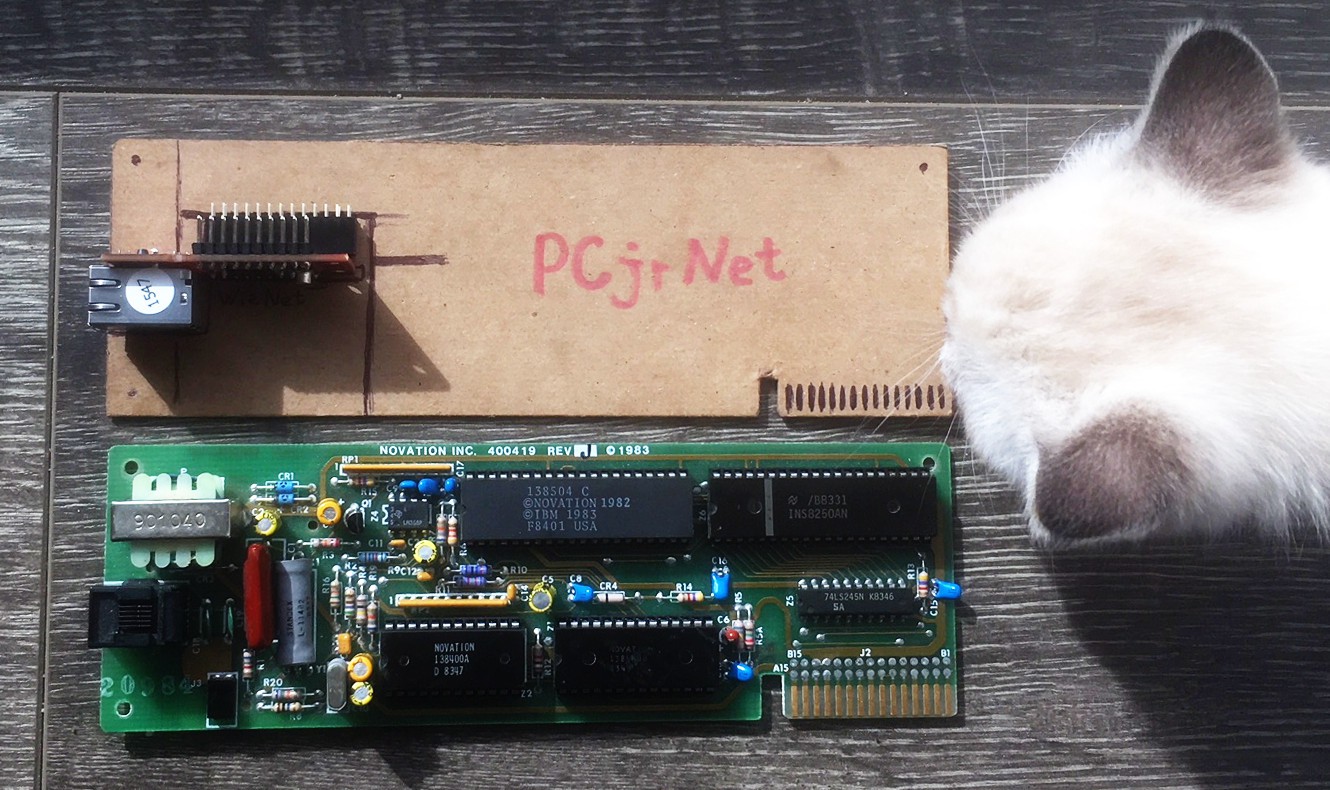
Actually that intermediate horizontal board may be turned into WizNET bread-board-friendly breakout board with 1 row of pins to make it easier to use WizNET module on standard solderless breadboard for prototyping purposes, but in this case it will be needed to extend address to all 15 address lines, so we will need to have no 21 pins, but 34 (3.5 inches long).
Discussions
Become a Hackaday.io Member
Create an account to leave a comment. Already have an account? Log In.