I had my Lego train out(that uses Lego power functions) and wanted to try controlling it using my TV-B-On remote. I did a bit of googling and found the datasheet on the IR protocol. I whipped up something quick and dirty. It didn't work. What was it? Was it the fact that I didn't send the code 5 times as per the specification? Do I actually need to count out 6 IR pulses (the stop/start bit, high and low bits all start with 6 IR pulses, it's just the delay after that differentiates them?) Do I need the send the 16 bits LSB first?
I first grabbed my Arduino Uno and uploaded the IRdump sketch from IRremote library, but the output wasn't too useful in this instance. I then pulled out my inexpensive logic analyzer and opened Pulseview(Sigrock.) I then proceeded down the rabbit hole of getting my code to count out exactly 6 IR pulses. Still not working. I then tried sending the 16 bits LSB first. Nope. I also tried sending the code 5 times as per the specification and still nothing. While I was at it, I hooked up my signal analyzer through a 3 pin IR receiver and discovered that per an IR burst it just shows up as one burst (the 6 IR pulses just shows up as a single large pulse.) So it wasn't critical to count out 6 IR pulses.
I then decided to find an Arduino Lego PF library, make up a sketch of the code that I was trying to send on my TV-B-On on my Uno, hook that up to my logic analyzer and examine the output. I found a working library here. A ran everything and decoded the bits (the PWM decoder in Pulseview made it easy to tell the 0,1, and stop/start bits apart.) I shortly discovered the problem. The problem was with the 4th nibble, the LRC data. The datasheet states that the LRC is calculated by doing an xor operation on the first three numbers and the number 0xf. I assumed that doing an xor operation on 4 numbers would work just like two numbers, is there is a single one bit in a particular position, the result is one, overwise it's zero like shown below:
1111
0100
1000
1000

result
0011
The bits that I decoded from the known working code however gave me 1011 instead. I looked up the rules for more than 2 numbers and found this from this website "To find each bit of XOR just calculate number of 1’s in the corresponding bits. If it is even or zero then that XOR’ed bit is 0. If it is odd then that XOR’ed bit is 1." I made the correction to my code and it worked. I did find out for the mode I was using at the time at least that I don't need to send the code 5 times with the specified delays per the datasheet.
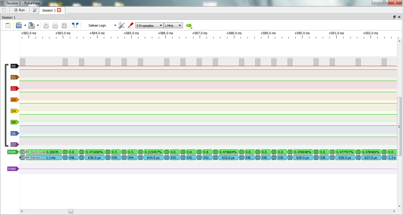
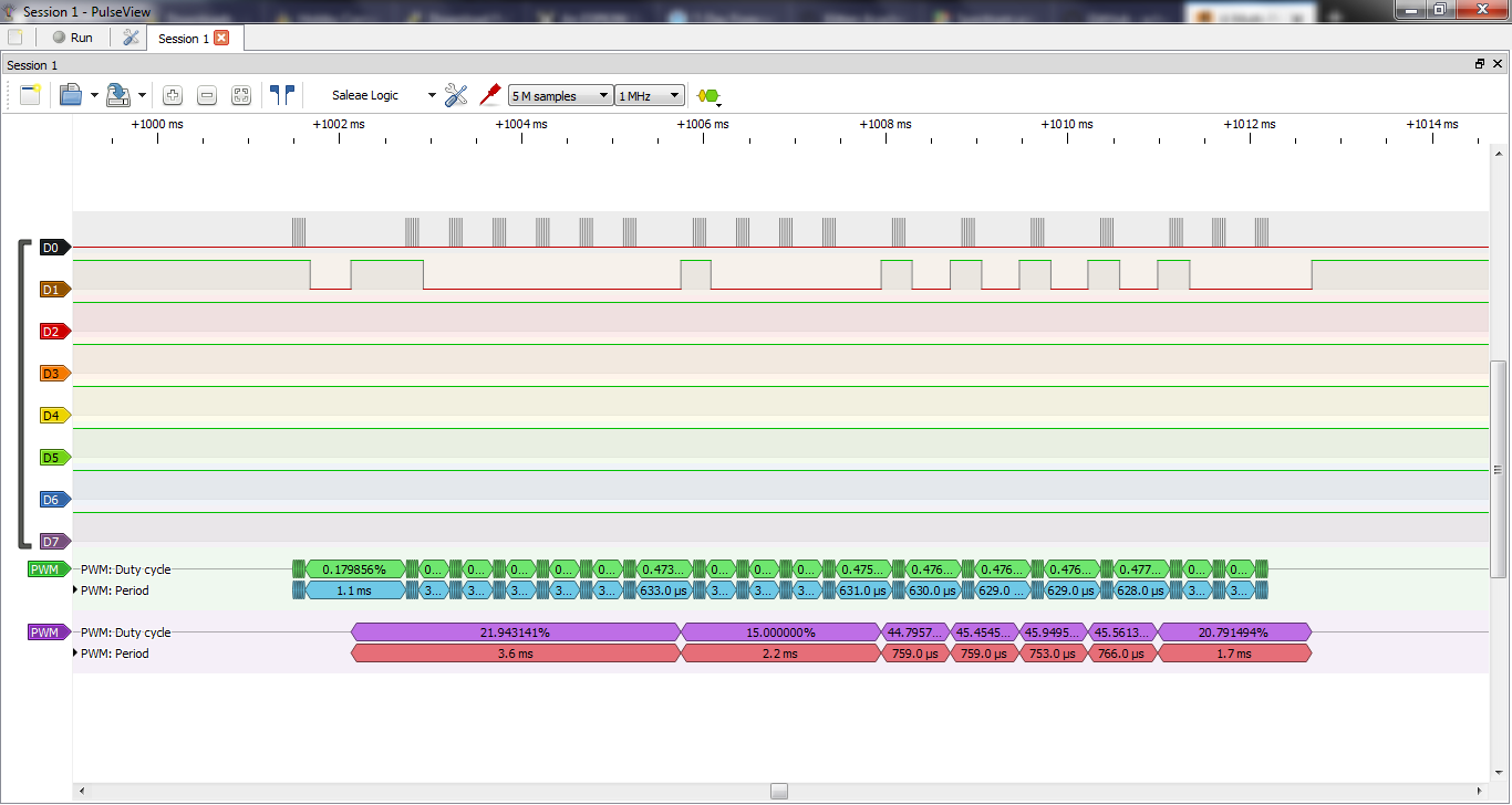
Here's a screenshot from pulseview of the generated output and I've also included my code that's still very much a work in progress.
EDIT: I've also included the capture both at the pin and thru an IR receiver. I'm not sure how to easily decode the capture thru the IR receiver.
#include <avr/io.h>
#include <avr/interrupt.h>
#define F_CPU 8000000UL //8 MHz
#include <util/delay.h>
void start_stop_bit(void);
void high_bit(void);
void low_bit(void);
void send_message(unsigned int mess);
void send_combopwm(char nib2, char nib3, char nib1);//blue,red,channel
void send_singleoutput(char mode, char output, char nib3, char nib1);//mode
//zero for red channel 1 for blue, command,channel
volatile int count=0;


#define PWM_FLT 0x0
#define PWM_FWD1 0x1
#define PWM_FWD2 0x2
#define PWM_FWD3 0x3
#define PWM_FWD4 0x4
#define PWM_FWD5 0x5
#define PWM_FWD6 0x6
#define PWM_FWD7 0x7
#define PWM_BRK 0x8
#define PWM_REV7 0x9
#define PWM_REV6 0xA
#define PWM_REV5 0xB
#define PWM_REV4 0xC
#define PWM_REV3 0xD
#define PWM_REV2 0xE
#define PWM_REV1 0xf


int main(void)
{
cli();//disable gobal interrupts
//pwm setup
DDRB |= 0b00000011; //set pin 6 as output pb1 and xmit led indicator pb0
//TCCR0A =0b00100011;//seting pwm clear and part of pwm mode
//TCCR0B =0b0001001;//set prescaler to /1
OCR0A = 212-1;
OCR0B=21; //about 10 percent duty cycle
TIMSK = 8;

//sleep mode setup
//sleep mode p 36 ish
MCUCR |=0b00010000;//enable shutdown mode
sei();//enable global interrupts


//send_combopwm(0x8,0x8,0);
send_singleoutput(0, 0,7, 0);


//additional power reduction
//disable analog comparator
ACSR =0b10000000;
PRR |=0b00001111;

MCUCR |=0b00100000; //enable sleep mode
asm("sleep");

}


//_delay_ms(1)


void start_stop_bit(void){
count=0;
TCCR0B =0b00001001;
TCCR0A =0b00100011;
_delay_us(157.8);
//TCCR0A =0b00000011;
_delay_us(1026.3);
}

void high_bit(void){
count=0;
TCCR0B =0b00001001;
TCCR0A =0b00100011;
_delay_us(157.8);
//TCCR0A =0b00000011;
_delay_us(552.6);
}

void low_bit(void){
count=0;
TCCR0B =0b00001001;
TCCR0A =0b00100011;
_delay_us(157.8);
//TCCR0A =0b00000011;
_delay_us(263.1);
}
void send_singleoutput(char mode, char output, char nib3, char nib1){

char nib2 = 4 | mode<<1 | output;
char nib4 = 0xf ^ nib1 ^ nib2 ^ nib3;

unsigned int message = nib1<<12 | nib2<<8 | nib3<<4 | nib4;

send_message(message);
}

void send_combopwm(char nib2, char nib3, char nib1){

nib1 = 0x4 | nib1;
char nib4 = 0xf ^ nib1 ^ nib2 ^ nib3;
unsigned int message = nib1<<12 | nib2<<8 | nib3<<4 | nib4;
send_message(message);

}

void send_message(unsigned int mess){

int count_send = 16;
_delay_ms(48);
PORTB |= 0b00000001; //turn on xmit led indicator
start_stop_bit();
while(count_send > 0){
    count_send--;
    if(mess &(1<<count_send)){
    high_bit();

    }
    else{
    low_bit();
    }


}
start_stop_bit();
PORTB &=~0b0000001; //turn off xmit led indicator

}
ISR(TIMER0_COMPB_vect) {
count++;
if(count >=7){
TCCR0A =0;
TCCR0B =0;
TCNT0 =0;
//count=0;
}
}
Discussions
Become a Hackaday.io Member
Create an account to leave a comment. Already have an account? Log In.