First things first, I'll post the current it draws from 2 AA batteries (rechargeables in my case) for 99%+ of the time when it's not being used as one of the contest rules was to include power measurements:
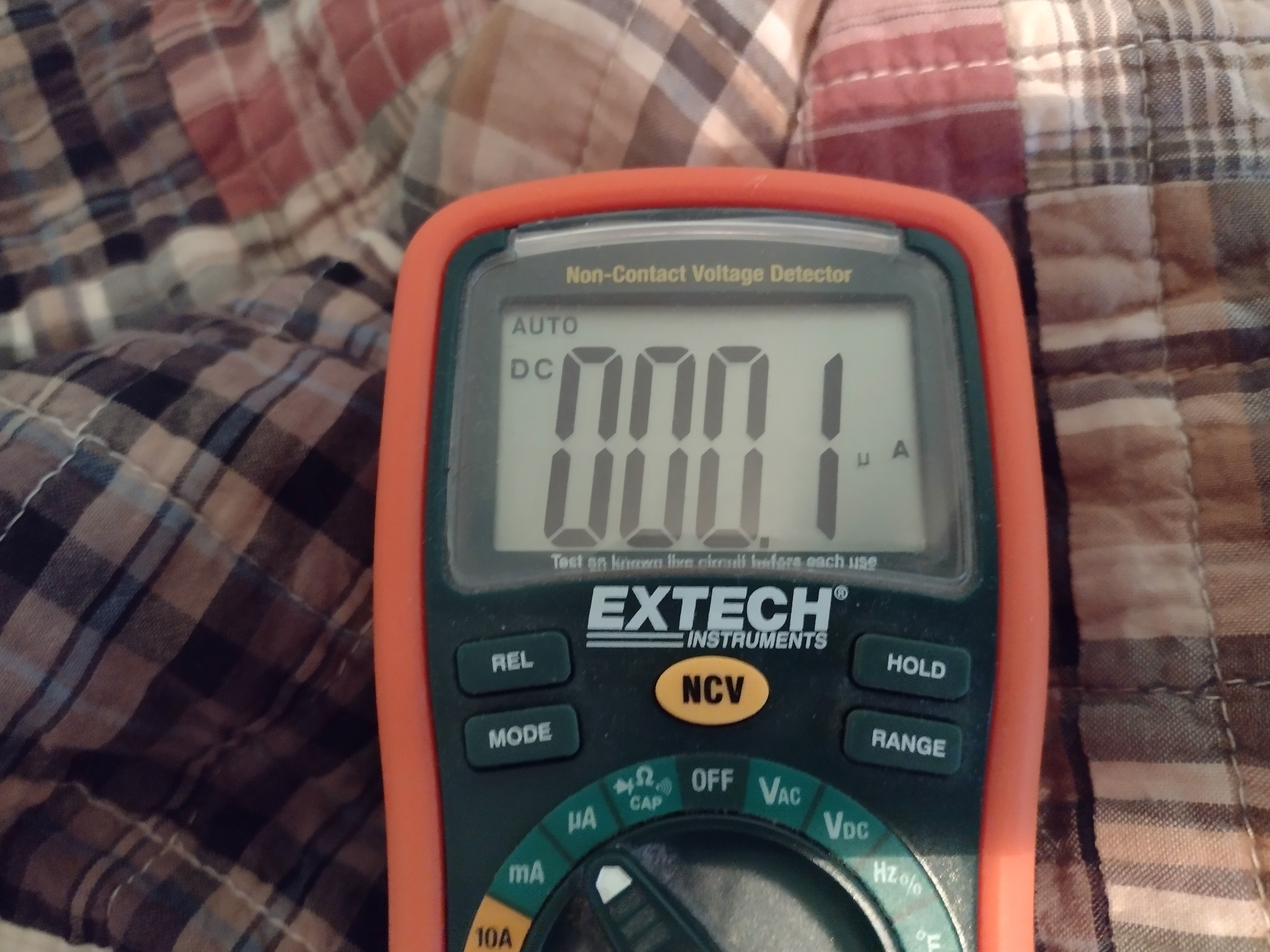
Using around a tenth of a microamp, means that the self-discharge of the batteries could very well be the limiting factor. The one that I regularly use for my living room TV has been running on 2, AA low-self discharge NiMh cells for over 2 years without recharging them.
I've assembled another board and have done some rather testing. The testing was a bit on the subjective side of things, but I've found some issues. A TV in another room that uses the same NEC protocol and uses the same code to turn the TV on/off that the living room TV uses, did not play so nicely with TV-B-On. It worked intermittently at best. I did some more research and some places state a recommended duty cycle of 1/4 to 1/3. Up until this point, I've been using a 10% duty cycle. That helped some, but it was still a bit inconsistent.
I also thought about improving the accuracy of the 38KHz signal. The timer I've used to generate the 38KHz signal ATTiny85 uses the system clock. Up until this point, I've set the ATTiny85 to use the internal RC oscillator as its clock source for the system clock. Let's take a look of the accuracy specs of that:
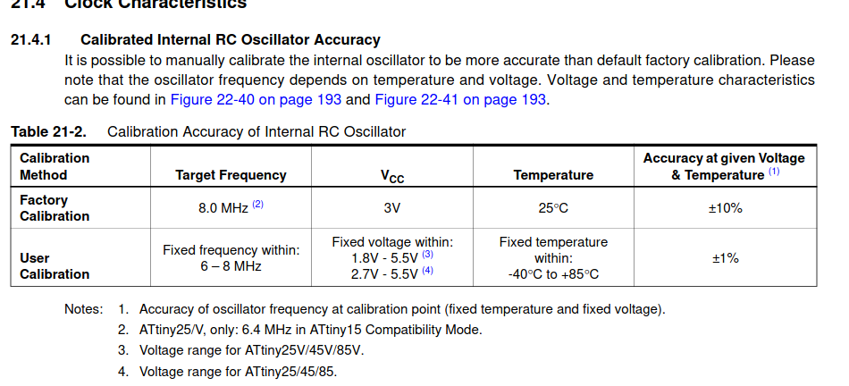
Yea, not exactly great accuracy. You can dial things in better either by changing the value in the OSCCAL register or by tweaking values used to set up the timer. The problems with doing this are two-fold. It has to be done on a chip by chip basis and the frequency varies depending on the supply voltage. It's a very finicky thing to do. The latter issue could possibly be mitigated by characterizing each chip on a range of voltage points and finding the best settings at those particular points, using the ADC to measure current supply voltage, and based on the ADC reading, select to closest set of optimal settings, but that's going down quite a rabbit hole. I did take some frequency measurements and did indeed find the signal was off anywhere from a hundred or so Hz to over a KHz or more.
There is a far better, simpler solution: use a freaking crystal. For a crystal frequency, I selected 4MHz. As to why I selected 4MHz vs. 8MHz which I have been using for the RC oscillator is for staying well within the recommended max frequency in respect to supply voltage. Running at 8MHz is perhaps running on the edge of things, especially when using nominal 1.2V NiMh cells, and double so when the voltage drops as the cells discharge. I have placed an order for some 8MHz crystals and could try it, although it's probably unnecessary. I took some frequency measurements using a 4MHz crystal, at it was almost bang-on 38KHz. Of course, fuse settings and program code had to be altered, but that didn't take much effort of time to do. I'm glad I made the provision to add a crystal when I designed the board, so a re-spin wasn't needed. I did re-validated the current draw when powered down after switching over to using the crystal, and there was no noticeable change.
Another thing to note: In most cases I tend to shy away from using a crystal with the ATTiny85. In most cases, the ATTiny85 has only 5 I/O pins to start with. Using a crystal, takes up 2 of those pins, leave only 3 pins for I/O. That wasn't a problem in this application, but that can be a major limitation. It would be really nice if Microchip would make a version of the ATTiny85 with a more accurate internal oscillator.
After switching over to the crystal, there did seem to be an improvement, but things still weren't quite right. Recharging the batteries resulted in a further improvement, but things can still be a little inconsistent.
My next course of action is more power! That is, to drive a bit more current though the IR LED. As it stands right now, depending on the particular model IR LED used and the battery voltage, peak current draw is only around 60 mA at most. It's common to overdrive IR LEDs multiple times of their rated max continuous current and it can be done without damage to those LEDs. Commonly found on datasheets for IR LEDs, is a peak current rating and under what conditions that peak current can safely be achived without risk of damage. For example, for a KingBright LED, model WP7113F3BT, the peak conditions are 1% duty cycle and a pulse width not exceeding 10 microseconds.
Up until now, I've been hesitant to do much in the way of over-driving, as not getting things right on the code side of things can result in a damaged/killed IR LED, but it looks like I may need to overdrive, as I haven't found much in the way of IR LEDs that have a continuous current rating over 100mA (most are limited to 50mA.) I'll likely use my logic analyzer to make sure things are operating as they should as a precaution.
Another thing to consider with IR LEDs is beam angle. an IR LED with a narrow beam will make better use of it's power, allowing for greater range but at the expense of requiring a more direct pointing at the IR receiver. I'll try to get some IR LEDs in with various beam angles for testing.
Okay, I've rambled on long enough. I should go to sleep and resume testing tomorrow.
Discussions
Become a Hackaday.io Member
Create an account to leave a comment. Already have an account? Log In.