 matseng
Matseng
@Ted Yapo , this link describes a latch a single transistor pulsed latch - I'm getting a feeling that it might be up your alley and that you might have some pointers for values and frequencies to use for trying it out. I couldn't get it anyway even close to working using ltspice - but I guess that that's just reasonable since it's based on changes in the CB capacitance that might not (?) be fully supported in most transistor models there..
https://web.archive.org/web/20090514061753/http://www.jdm.homepage.dk:80/refresh.htm
Ted Yapo
no matter what my dog is doing, when I say the word "treat", he drops it and gives me full attention. I'm the same way with the phrase "single transistor X"
love the ASCII art, will have a look
Matseng
Great! Hopefully RF would not be required as in your DDL ;-)
Ted Yapo
that transistor symbol looks like the ones you use
Matseng:
Ah yes... Now when you mention it I can see it. Definitely the same. Maybe it was especially popular in Scandinavia back in the late 70's ;-)
Ted Yapo:
I would try a power transistor to start. Your average small-signal one will have Cbe's in the low pF range (4 pF for the 2N3904). Big, slow power transistors like the 2N3055 will have a much higher value, and may be easier to get working
I mean Ccb (noted as output capacitance on the datasheet)
@matseng Look for SPICE BJT models with values for MJE and MJC, which model the voltage-dependence of the junction capacitances (see this pdf for how it works : https://ecee.colorado.edu/~bart/book/book/chapter5/pdf/ch5_6_3.pdf).
LTspice's model for the 2N3904 does not include these factors (nor does the 2N3055). You might find a better model elsewhere.
@matseng It definitely looks like a bench exercise. But, you could fake it in LTspice by adding an external capacitor across the transistor to model each state. At least, you could see how it's supposed to work, and if you guess the additional capacitance.
As for values, I would probably resort to trial-and-error in sims. Try a value from every decade from 100 ohms to 100 meg or so.
@matseng try this. It may be completely wrong, but it seems to work as a latch. Interchange the spice directives and comments to get the other state.

it simulates the CB capacitance with an external cap
Matseng
@Ted Yapo Oh, that's great work! Thanks a lot! I'll play around with it in spice and see if I can get anything working IRL as well.
I've got sooo much to learn about spice...
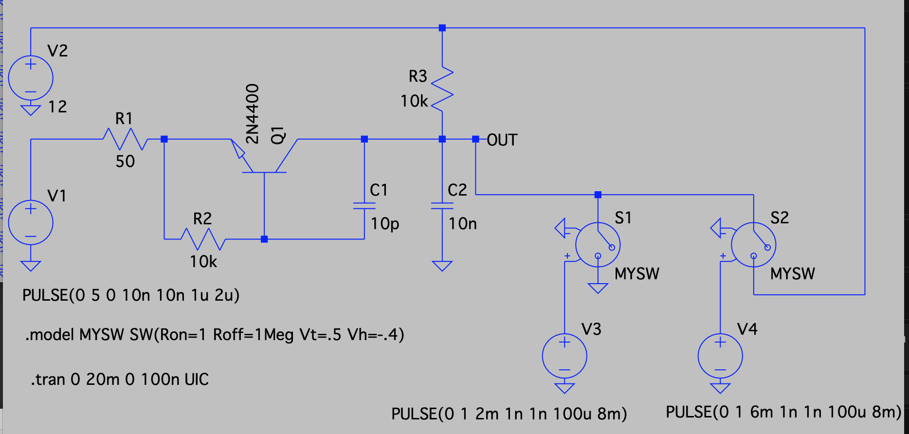
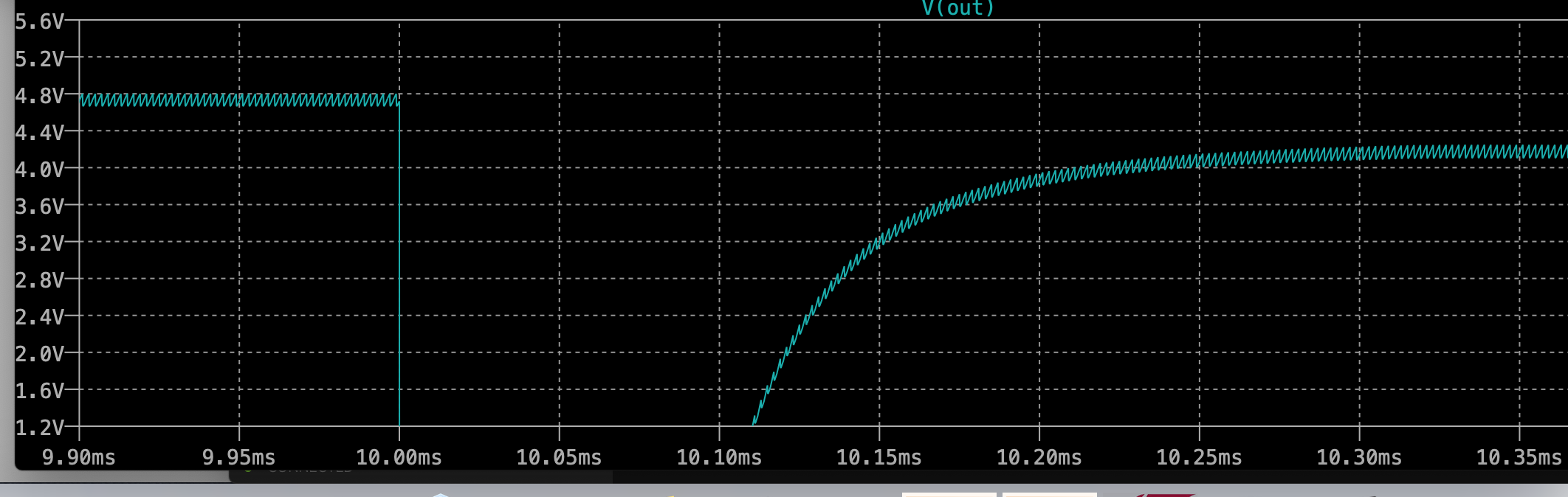
@Ted Yapo Yes, it seems to work pretty well with a 2n4400 and a fixed extra Ccb of 10p. I added two voltage controlled switches that for 100 us pulls the output either to GND or VCC at 2 ms intervals. The new state after each pull have a delta of about 500mV from the previous state. That is really kinda cool.
Not sure if the reduction of number of components compared to a simple fet or bjt FF is worth the extra effort though... But as a general concept it's a neat idea.
(I mean latch, not FF)
Discussions
Become a Hackaday.io Member
Create an account to leave a comment. Already have an account? Log In.