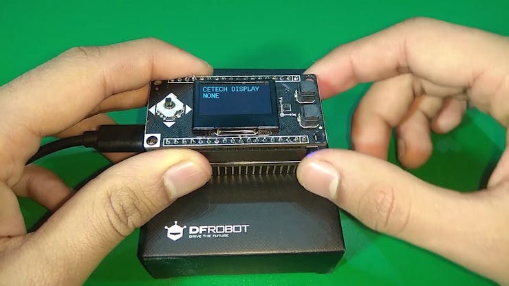
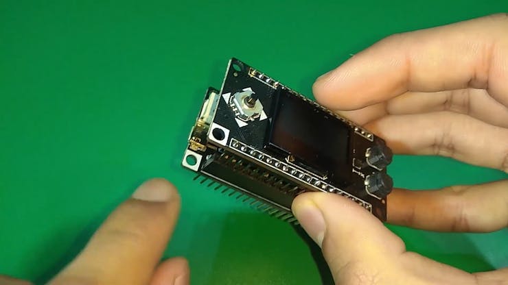
• 1
    Step 1: Parts

    To make this you will need an ESP8266 board and you can also add a battery if you want.

    I suggest to use a board from DFRobot with this module as the pinout will be compatible and you will face no issues anywhere, I used Firebeetle board from DFRobot as it has on board battery charging and monitoring solution.

    I would also recommend using a PCB to make some project using this module so that adding battery/OLED display/switch/esp8266 doesnt remain difficult. You can order your PCBs from PCBWAY as they offer 10 PCBs for just 5$. Check out their online Gerber viewer function.

    The Firebeetle board ESP8266
  • 2
    Step 2: Download and set up the Arduino IDE

    Download the Arduino IDE from here.

    1. Install the Arduino IDE and open it.

    2. Go to File > Preferences

    3. Add http://arduino.esp8266.com/stable/package_esp8266com_index.jsonto the Additional Boards Manager URLs.

    4. Go to Tools > Board > Boards Manager

    5. Search for ESP8266 and then install the board.

    6. Restart the IDE.

  • 3
    Step 3: Prepare the parts

    1. Solder the headers on the OLED shield as well as the microcontroller module.

    TIP: Use a breadboard to align the headers and then solder the module keeping the headers inserted into the breadboard.

    2. Align the Corners with the white colors on the on both the modules and stack them using the headers. Now connect the board to the PC.